SUW210 - TV wall mount SONY - Free user manual and instructions
Find the device manual for free SUW210 SONY in PDF.
| Brand | Sony |
| Model | SUW210 |
| Product type | Wall mount for TV |
| Compatibility | Sony LCD TVs KLV-23HR2 / KLV-21SR2 / KLV-21SG2 / KLV-20SR3 / KLV-L23M1 |
| Maximum load | 12 kg |
| Weight of mount | Approx. 1.6 kg |
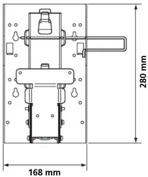
| Dimensions (L × H) | 280 × 168 mm |
| Depth (depending on angle) | 55 mm (0°) / 63 mm (5°) / 71 mm (10°) |
| Tilt angles | 0°, 5°, 10° |
| Material | Steel / metal |
| Color | Black (typical) |
| Package contents | Brackets Ⓐ (x1), Ⓐ (x3 for 0°/5°/10°), Ⓑ (x1), Ⓓ (x1), Ⓔ (x1), locking rod, screws (x6 with washer) |
| Installation | Wall mounting requires skills; recommended by a Sony professional |
| Maintenance | Clean with a soft dry cloth; do not use solvents |
| Safety | Do not exceed the maximum load; lock with the locking rod; do not climb on the TV |
| Standards | Compliant with CE safety requirements |
Frequently Asked Questions - SUW210 SONY
User questions about SUW210 SONY
0 question about this device. Answer the ones you know or ask your own.
Ask a new question about this device
Download the instructions for your TV wall mount in PDF format for free! Find your manual SUW210 - SONY and take your electronic device back in hand. On this page are published all the documents necessary for the use of your device. SUW210 by SONY.
USER MANUAL SUW210 SONY
- This Wall-Mount Bracket is designed for use with the Sony KLV-23HR2/KLV-21SR2/KLV-21SG2/KLV-20SR3/KLV-L23M1 LCD Colour TV.
Gebrauchsanweisung
Thank you for purchasing this product.
For Customers
Sufficient expertise is required for installing this product, especially to assure the strength of the wall. Be sure to entrust the attachment of this product on the wall (Step 1 to Step 3 in “Installation”) to Sony dealers or contractors and pay adequate attention to safety during the installation. We are not liable for any damage or injury caused by mishandling or improper installation. Your Statutory Rights (if any) are not affected.
WARNING
To avoid risk of serious injury or damage to the TV caused by dropping it, observe the following precautions.
- Do not hang from the TV or the Wall-Mount Bracket installed on the wall.
- Be careful not to trap the AC power adapter cord of the TV when you secure the TV to the Wall-Mount Bracket.
- Follow the installation procedures and installation direction described in this manual.
For a safety installation, consult your Sony dealer or qualified service personnel. - Before installing, confirm that the wall has sufficient strength to support the TV and the Wall-Mount Bracket. The installation location should be a flat, perpendicular wall with a reinforcing material inside.
- Do not apply a weight other than the TV to the Wall-Mount Bracket installed on the wall.
- Do not disassemble, modify or change the parts of the Wall-Mount Bracket.
For Sony Dealers
Sufficient expertise is required for installing this product. Be sure to read this instruction manual thoroughly to do the installation work safely. We are not liable for any damage or injury caused by mishandling or improper installation. After installation, please hand this instruction manual to the customers.
Caution
- This Wall-Mount Bracket is only for the specified Sony LCD Colour TVs. Do not use the bracket with a TV whose operating instructions do not specify the use of this bracket.
- Be especially careful not to drop the TV when you install it high on a wall.
Installation
For Sony Dealers
For the installation, have ready eight commercially available mounting screws, anchor bolts, etc. that are appropriate for the wall.
The type and length of the screws required depend on the material and strength of the wall. If you do not know which material your wall is made of, consult your Sony dealer or qualified service personnel.
Step 1: Check the parts
Check all the parts are included in the package.
Bracket A (1)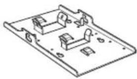 | Bracket C (3)(0°, 5°, 10°) | Bracket E (1) Screw 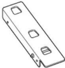 | (with washer) |
| Bracket B (1)[IMAGE] | Bracket D (1)[IMAGE] | Locking rod (1)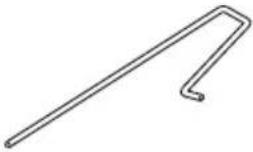 |
Step 2: Decide the installation location
Decide the location on the wall to install the TV.
Then, place bracket Ⓐ on the installation location and mark the four screw holes on the wall using a pencil.
Before marking the location of the holes, make sure that the distance between the upper edge of bracket Ⓐ and the ceiling is 15 cm or more, and that between the side edge of bracket Ⓐ and the side wall is 25 cm or more.
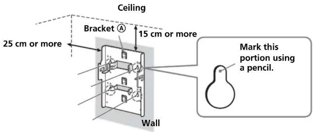
Note
Attach bracket Ⓐ level with the floor.
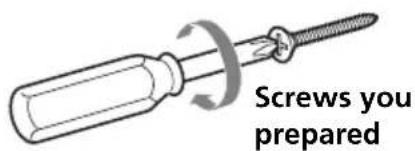
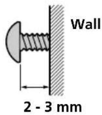
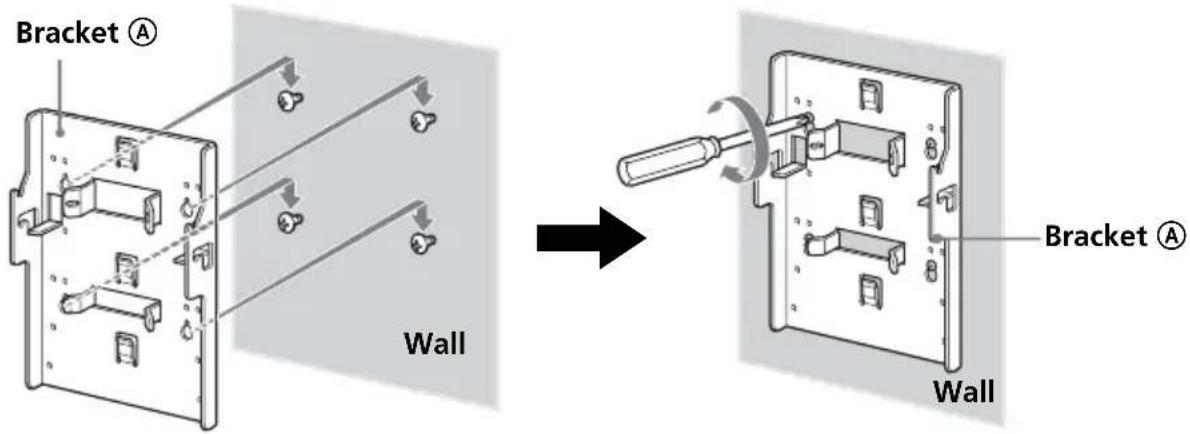
Step 3: Secure bracket Ⓐ to the wall
1 Insert four of the screws you prepared at the positions marked in Step 2 (page 4).
Do not tighten the screws completely for the moment. Keep a space of 2 to 3 mm from the wall.
2 Press bracket Ⓐ to the wall and slide it down. Then fully tighten the four screws on the wall.
3 Insert four of the screws you prepared in the screw holes, and tighten them securely in the order of ① to ④ as shown below.
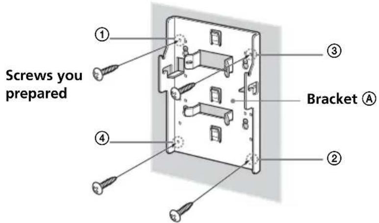
continued
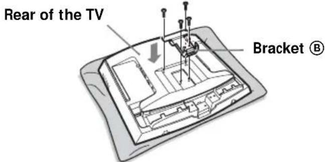
Step 4: Attach bracket Ⓑ to the TV
Before attaching bracket Ⓑ, remove the rear cover of the TV and disconnect all the cables from the TV.
For how to remove the rear cover of the TV, refer to the Operating Instructions supplied with the TV.
(The illustrations used in this manual show the KLV-21SR2/KLV-L23M1 as examples.)
1 Remove the screws as shown below, and remove the TV stand from the TV.
To prevent damaging the surface of the LCD display, place the TV on a soft mat.
KLV-21SR2 KLV-L23M1
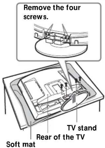
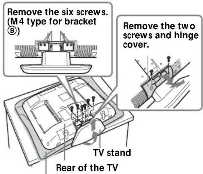
To secure bracket Ⓑ to the TV, use the screws removed from the TV stand, not the ones from the hinge cover.
Notes
- Place the TV body only on the table as shown above. If the TV stand is also on the table, the TV body may be unstable and cause damage.
- When removing the TV stand, hold it firmly.
2 Secure bracket Ⓑ to the TV firmly using the four screws removed in step 1.
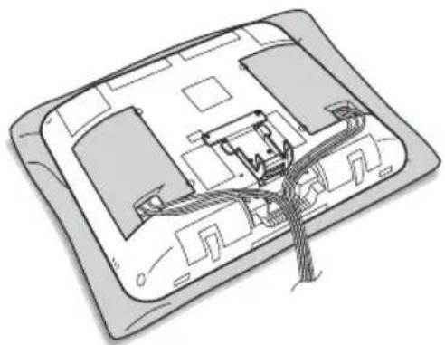
Step 5: Attach the rear cover on the TV
(The illustrations used in this manual show the KLV-21SR2/KLV-L23M1 as examples.)
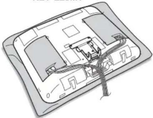
1 Connect the cables.
How to connect/bundle the cables differs depending on the TV model. For details, refer to the Operating instruction for your TV.
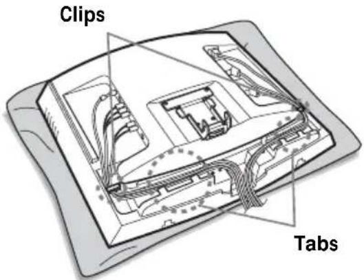
Note
If the cables are not neatly stored in the grooves, you may not be able to attach the rear cover.
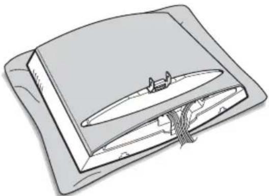
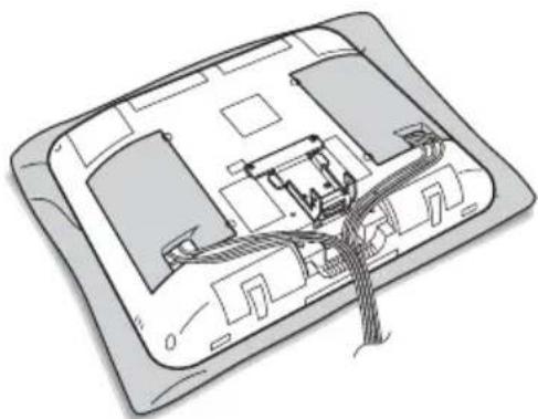
Attach the rear cover.
For KLV-L23M1, attach the cable covers instead of the rear cover. For KLV-20SR3, go to Step 6 instead of attaching the rear cover.
For details on how to attach the rear cover, refer to the Operating Instructions of the TV.
KLV-21SR2
natural_image
Illustration of an open book with a bookmark and cable inserted, no text or symbols presentKLV-L23M1
natural_image
Diagram of a device interior showing internal components and wiring (no text or labels)Note
When you attach the rear cover, make sure that bracket Ⓑ does not damage the rear cover.
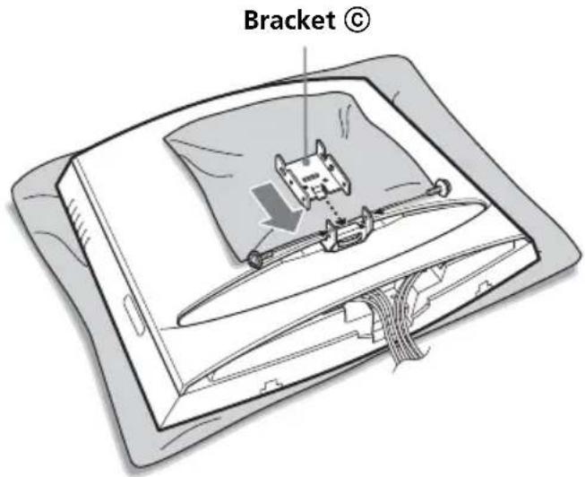
Step 6: Attach brackets Ⓒ, Ⓓ, and Ⓔ to the TV
To prevent damaging the surface of the rear cover of the TV, put a soft mat on the rear cover.
1
Attach bracket © of the desired angle to bracket Ⓑ.
Insert the hooked part of bracket Ⓐ into bracket Ⓑ as illustrated below. Confirm that both sides of bracket Ⓐ are outside bracket Ⓑ, and secure them firmly with two of the supplied screws.
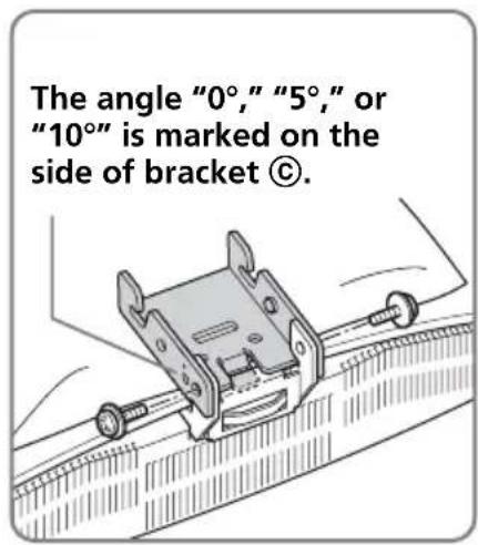
There are three types of bracket Ⓒ, each with a different angle: 0°, 5°, and 10°. Choose the bracket ⓒ with the desired angle to attach.
The illustration below shows an example of how to attach bracket Ⓒ with an angle of 0^ .
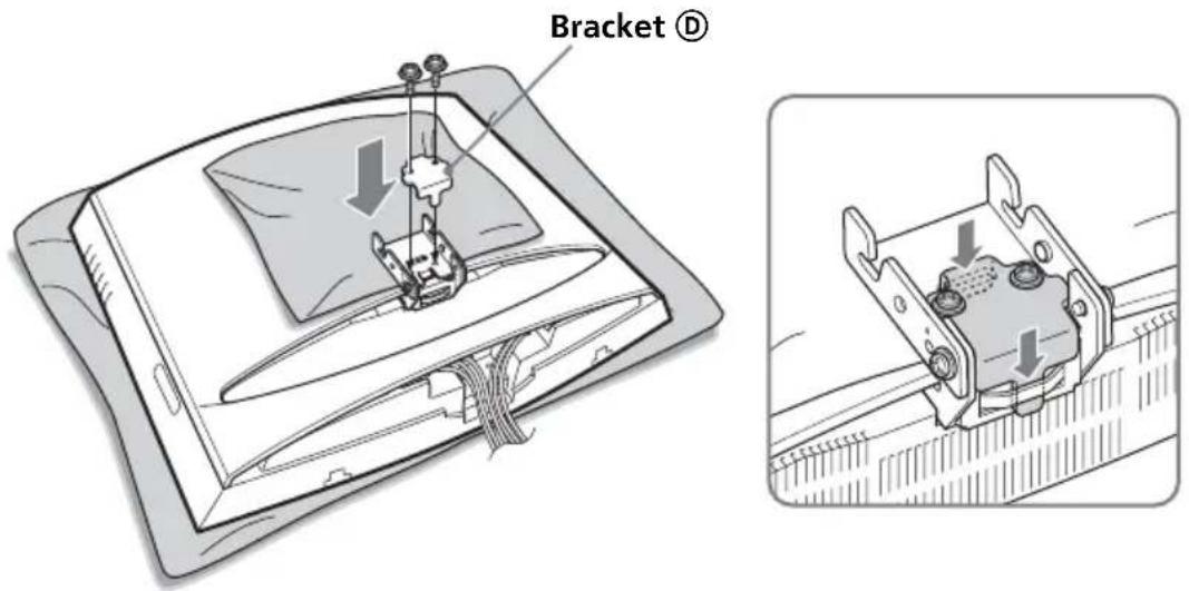
2
Attach bracket Ⓓ to bracket Ⓒ, and secure them firmly with two of the supplied screws.
Place bracket Ⓓ onto bracket Ⓒ as illustrated below, and secure them with the two screws.
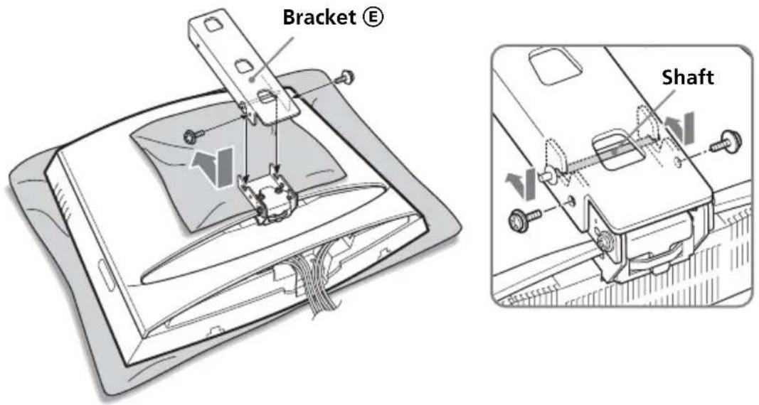
3
Attach bracket Ⓔ to bracket Ⓒ, and secure them firmly with two of the supplied screws.
Slide the shaft of bracket Ⓔ into the notches of bracket Ⓒ as illustrated below, and secure them with the two screws one on each side. When you complete attaching bracket Ⓔ, remove the soft mat from the rear cover of the TV.
Note
Be careful not to get your fingers caught between the brackets when attaching them.
Step 7: Secure the TV to the wall
1
Hook bracket Ⓔ on bracket Ⓐ.
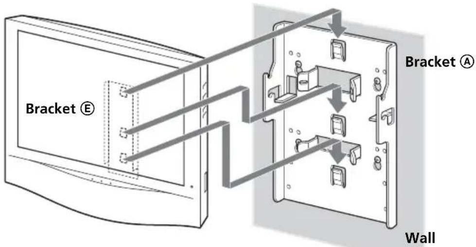
Notes
- Hold the TV firmly. Be especially careful when you secure the TV in a high place.
- Do not release the TV until you confirm that bracket Ⓔ is firmly secured to bracket Ⓐ at three locations.
2
Insert the locking rod.
The locking rod can be inserted from either side. The illustration below shows an example of how to insert the locking rod from the right side.
①Insert the longer side of the locking rod into the holes on bracket ⑧.
②Insert the curved side of the locking rod into the hole on bracket Ⓐ. Hold and press the locking rod at part ⓐto pass its end through the hole.
③Turn the locking rod until it stops to secure it in place.
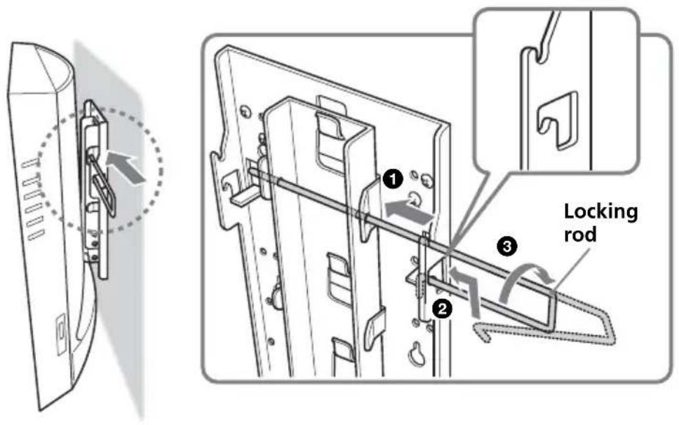
Note
To prevent the locking rod from falling out of the brackets, the space between both ends of the locking rod is greater than that between the holes on the brackets. Hold and press the locking rod at part a so that it can pass through the holes.
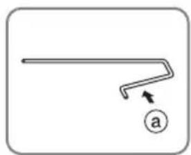
natural_image
Simple line drawing of a bent pipe or channel with an arrow and a labeled point 'a' (no text or symbols beyond the label)Caution
If the TV is lifted up when the locking rod is not installed properly, the TV may fall off the Wall-Mount Bracket and cause serious injury.
Be sure to insert and secure the locking rod in place.
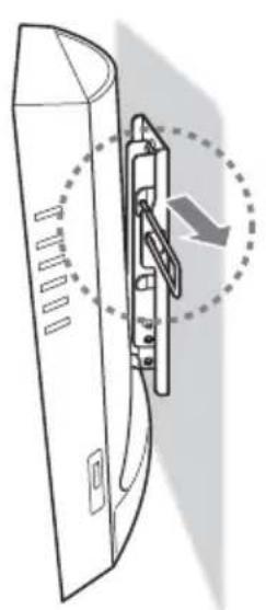
Detaching the TV from the Wall-Mount Bracket
Remove the locking rod from brackets Ⓐ and Ⓔ, then detach the TV from the Wall-Mount Bracket.
natural_image
Diagram of a door handle assembly with a dashed circular arrow indicating direction (no text or symbols)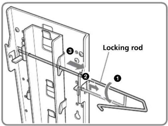
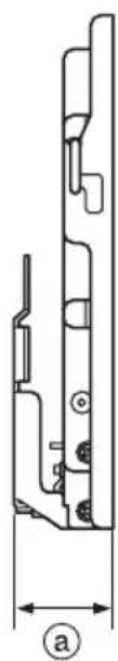
Specifications


natural_image
Technical line drawing of a mechanical component with dimension label (a), no readable text or symbols present.Value Ⓢ varies depending on the angle of bracket Ⓒ.
| Bracket © angle | a |
| 0° 55 mm | |
| 5° 63 mm | |
| 10° 71 mm |
Bracket mass: Approx. 1.6 kg
Supportable weight: Approx. 12 kg
Design and specifications are subject to change without notice.
natural_image
Simple line drawing of a bent pipe or channel with an arrow and a circled label 'a' (no text or symbols beyond the label)Vorsicht
natural_image
Technical line drawing of a mechanical component with dimension label (a), no readable text or symbols present.natural_image
Illustration of a device with a central component and cable, no visible text or symbolsnatural_image
Technical line drawing of a mechanical clamp or bracket assembly mounted on a ruler (no text or symbols visible)2
natural_image
Technical illustration of a device with a clamping mechanism and its internal mounting bracket (no text or symbols)3
natural_image
Simple line drawing of a bent pipe or rod with an arrow and circled number ① (no text or symbols)Attention
natural_image
Technical line drawing of a mechanical component with dimension label (a), no readable text or symbols present.wordt vervolgd
Stap 4: Steun Ⓑ op de TV bevestigen
natural_image
Two technical line drawings of an open electronic device showing internal components and wiring (no text or symbols)Opmerking
natural_image
Simple line drawing of a bent pipe or rod with an arrow and circled number 'a' (no text or symbols)Let op
natural_image
Diagram of a door handle assembly with a dashed circular arrow indicating direction (no text or symbols)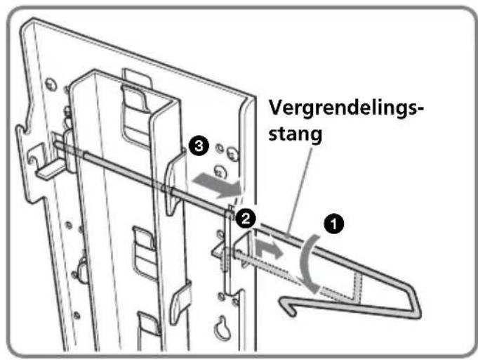
Technische gegevens
natural_image
Technical line drawing of a mechanical component with dimension label (a), no readable text or symbols present.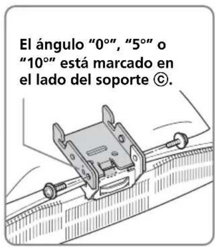
Notas
natural_image
Simple line drawing of a bent pipe or rod with an arrow and a labeled point 'a' (no text or symbols beyond the label)Precaución
natural_image
Technical line drawing of a mechanical component with dimension label (a), no readable text or symbols present.natural_image
Simple line drawing of a bent pipe or rod with an arrow and a circled label 'a' (no text or symbols beyond the label)Avvertimento
natural_image
Diagram of a door handle assembly with a dashed circular arrow indicating direction (no text or symbols)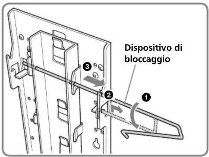
natural_image
Technical line drawing of a mechanical component with dimension label (a), no readable text or symbols present.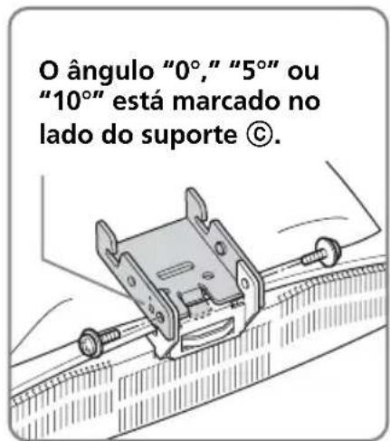
natural_image
Simple line drawing of a bent pipe or rod with an arrow and a labeled point 'a' (no text or symbols beyond the label)Cuidado
natural_image
Technical line drawing of a mechanical component with dimension label (a), no readable text or symbols present.natural_image
Simple line drawing of a bent pipe or channel with an arrow and a labeled point 'a' (no text or symbols beyond the label)Att tänka på!
natural_image
Technical line drawing of a mechanical component with dimension label (a), no readable text or symbols present.natural_image
Two technical line drawings of an open electronic device with internal components, shown from different angles (no text or symbols present)Bemærk!
natural_image
Simple line drawing of a bent pipe or channel with an arrow and a circled label 'a' (no text or symbols beyond the label)Forsigtig!
natural_image
Technical line drawing of a mechanical component with dimension label (a), no readable text or symbols present.natural_image
Simple line drawing of a bent pipe or rod with an arrow and a circled number 'a' (no text or symbols)Varoitus
natural_image
Technical line drawing of a mechanical component with dimension label (a), no readable text or symbols present.natural_image
Illustration of an open notebook with a bookmark and cable inserted (no text or symbols)KLV-L23M1
natural_image
Diagram of an electronic device interior showing internal components and wiring (no text or labels)Примечание
natural_image
Illustration of a sewing machine needle stitching fabric on a flat panel (no text or symbols)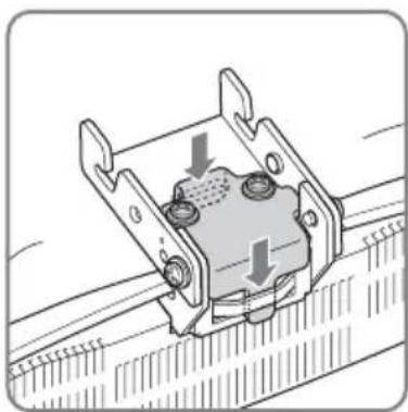
natural_image
Mechanical component diagram showing a bracket with mounting holes and directional arrows indicating movement (no text or symbols)3
natural_image
Simple line drawing of a bent pipe or channel with an arrow and a labeled point 'a' (no text or symbols beyond the label)Внимание
natural_image
Diagram of a door handle assembly with a dashed circular arrow indicating direction (no text or symbols)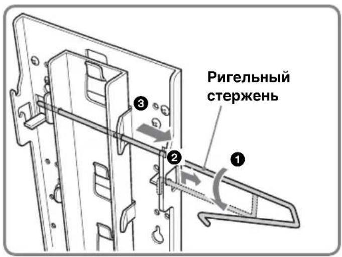
natural_image
Technical line drawing of a mechanical component with dimension label (a), no readable text or symbols present.natural_image
Illustration of an open book with a bookmark and cable, no text or symbols presentKLV-L23M1