MEGA 600 D - Compressor METABO - Free user manual and instructions
Find the device manual for free MEGA 600 D METABO in PDF.
User questions about MEGA 600 D METABO
0 question about this device. Answer the ones you know or ask your own.
Ask a new question about this device
Download the instructions for your Compressor in PDF format for free! Find your manual MEGA 600 D - METABO and take your electronic device back in hand. On this page are published all the documents necessary for the use of your device. MEGA 600 D by METABO.
USER MANUAL MEGA 600 D METABO
KONFORMITÄTSERKLÄRUNGIDECLARATION OF CONFORMITY
We herewith declare in our sole responsibility that this product complies with the following standards in accordance with the regulations of the undermentioned Directives testreport issuing test office measured/ guaranteed noise sound power level
NL
2006/42/EG, 2004/108/EG, 2000/14/EG Annex VI, P<15KW
CE-DE10-143677
*LwA=92dB/1pW - LwA=95dB/1pW
Volker Siegle
Director Innovation, Research and Development
Dokumentationsbevollmachtigter/ responsible person for documentation/ Chargé de la documentation

Metabowerke GmbH
Metabo-A/lee 1
D-72622Nuringen
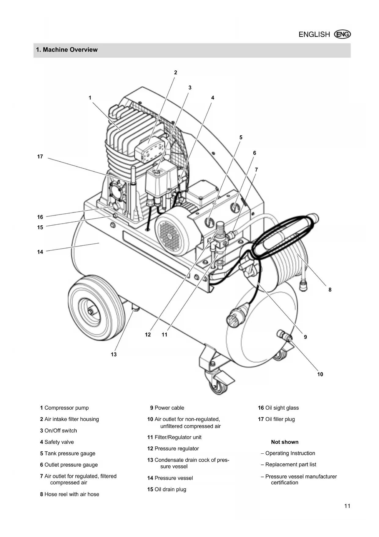
1 Compressor pump
2 Air intake filter housing
3 On/Off switch
4 Safety valve
5 Tank pressure gauge
6 Outlet pressure gauge
7 Air outlet for regulated, filtered compressed air
8 Hose reel with air hose
9 Power cable
10 Air outlet for non-regulated, unfiltered compressed air
11 Filter/Regulator unit
12 Pressure regulator
13 Condensate drain cock of pressure vessel
14 Pressure vessel
15 Oil drain plug
16 Oil sight glass
17 Oil filler plug
Not shown
-Operating Instruction
- Replacement part list
-Pressure vessel manufacturer certification
Table of Contents
- Machine Overview 11
- Please Read First! 12
- Safety 12
3.1 Specified conditions of use 12
3.2 General safety instructions 12
3.3 Symbols on the machine 13
3.4 Safety devices.. 13 - Operation 13
4.1 Mains connection 13
4.2 Installation 14
4.3 Generating compressed air..... 14 - Care and Maintenance 14
5.1 Periodic maintenance 14
5.2 Machine storage 15 - Available Accessories .... 15/78
- Trouble Shooting 17
- Repairs 17
- Environmental protection. 17
- Technical Specifications 18
2. Please Read First!
- Read these instructions before use. Pay special attention to the safety instructions.
- If you notice transport damage while unpacking, notify your supplier immediately. Do not operate the machine!
- Dispose of the packing in an environmentally friendly manner. Take to a proper collecting point.
- Keep these instructions for reference on any issues you may be uncertain about. When the compressor is used commercially, also keep the test certificates of the individual compressed air components.
- If you lend or sell this machine be sure to have the instructions go with it.
3. Safety
3.1 Specified conditions of use
This machine is intended to generate compressed air required for the operation of air tools.
Any use for medical purposes, food processing as well as filling of oxygen cylinders for breathing equipment is not permitted.
Explosive, combustible gases or gases detrimental to health may not be com
pressed. Operation in hazardous locations is not permitted.
Any other use is not as specified. Use not as specified, alteration of the machine or use of parts not approved by the equipment manufacturer, can cause unforeseeable damage!
Children, juveniles and persons not having been instructed in its usage are not permitted to operate this machine and any air tools connected to it.
3.2 General safety instructions
When using this electric tool observe the following safety instructions, to exclude the risk of personal injury or material damage.
Please also observe the special safety instructions in the respective chapters; Keep all documents, supplied with the machine, for future reference.
Observe the statutory accident insurance institution regulations and regulations for the prevention of accidents pertaining to the operation of air compressors and air tools, where applicable.
As a commercial operator, observe the legal regulations regarding the operation of systems subject to technical inspections.

General Hazard!
Keep your work area tidy - a messy work area invites accidents.
Be alert. Know what you are doing. Set out to work with reason. Do not operate electric tool while under the influence of drugs, alcohol or medication.
Consider environmental conditions.
Keep work area well lighted.
Prevent adverse body positions. Ensure firm footing and keep your balance at all times.
Make sure the electric tool stands safely and can not topple over (check air pressure of tyres).
Do not operate electric tool near inflammable liquids or gases.
Keep bystanders, particularly children, out of the work area. Do not permit other persons to touch the tool or power cable while the electric tool is running.
Do not overload electric tool - use it only within the performance range it was designed for (see Technical Specifications).

Danger! Risk of electric shock!
Do not expose electric tool to rain.
Do not operate electric tool in damp or wet environment.
Prevent body contact with earthed objects such as radiators, pipes, cooking
stoves or refrigerators when operating this electric tool.
Do not use the power cable for any purpose it is not intended for.
Risk of personal injury by escaping compressed air and parts hurled about by escaping air!
Never direct compressed air against persons or animals!
Ensure all air tools and accessories used are designed for the working pressure or are supplied via a pressure regulator.
Please note that, when disconnecting the quick coupler, the compressed air contained in the pressure hose will escape all of a sudden. You should therefore firmly hold the air hose when disconnecting it.
Ensure all screwed connections are fully tightened at all times.
Do not attempt to repair the machine yourself! Only trained specialists are permitted to service or repair compressors, pressure vessels and air tools.
Hazard generated by lubricated compressed air!
Use lubricated compressed air only for air tools requiring such supply. Do not use an air hose, used to supply lubricated compressed air, to supply air tools not designed for operation on lubricated compressed air. Do not fill tires with lubricated compressed air.
Risk of burns from the surfaces of parts carrying compressed air!
Let tool cool off before servicing.
Risk of personal injury and crushing by moving parts!
Do not operate the electric tool without installed guards.
Please note that the compressor will start automatically when the pressure falls off to minimum! - disconnect from power supply prior to any servicing.
Ensure that when switching on (e.g. after servicing) no tools or loose parts are in the electric tool.
When coiling the air hose up or uncoiling it, do not reach between the crank and the transport handle.
Hazard generated by insufficient personal protection gear!
Wear hearing protection.
Wear safety glasses.
Wear mask respirator when work generates dust or mist detrimental to health.
Wear suitable work clothes. When working outdoors wearing of non-slip shoes is recommended.
Hazard generated by electric tool defects!
Do not make changes to the device. Each change on parts which conduct compressed air leads to invalidation of the examination. Work on compressed air devices must only be carried out by specialists.
Keep electric tool and accessories in good repair. Observe the maintenance instructions.
Make sure that the device is maintained and checked regularly.
Check the electric tool for any damage each time prior to operation: Prior to further use of the electric tool, safety devices and protection devices must be carefully checked for flawless and proper function. Check to see that all moving parts work properly and do not jam. All parts must be correctly installed and meet all conditions necessary for the proper operation of the electric tool.
Damaged protection devices or parts must be repaired or replaced by a qualified specialist. Have damaged switches replaced by a service centre. Do not operate electric tool if the switch can not be turned ON or OFF.
Keep handles free of oil and grease.
3.3 Symbols on the machine
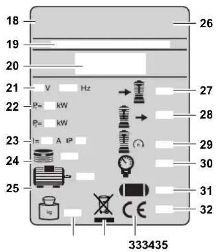
Data on the nameplate:
(18) Manufacturer
(19) Item no., version no., serial no.
(20) Machine designation
(21) Supply voltage / frequency
(22) Motor capacity P 1 (see also "Technical Specifications")
(23) Fuse protection / protection class
(24) No. of cylinders
(25) Motor speed
(26) Country code
(27) Suction capacity
(28) Filling rate
(29) Speed compressor pump
(30) Max. pressure
(31) Pressure vessel volume
(32) Year of make
(33) CE-mark - This machine complies with the EU Directives as per declaration of conformity
(34) Waste disposal symbol - Device can be disposed of by returning it to the manufacturer.
(35) Weight
Maintenance sticker
3.4 Safety devices
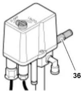
Safety valve
The spring-loaded safety valve (36) is incorporated into the pressure switch. The safety valve opens if the max. permissible pressure is exceeded.
4. Operation
4.1 Mains connection
Danger! High Voltage
Operate machine in dry environment only.
Operate machine only on a power source complying with the following requirements:
- outlets properly installed, earthed and tested;
- fuse protection in accordance with the technical specifications.
Position power cable so it does not interfere with the work and is not damaged.
Always check to see that the machine is switched OFF before plugging in.
Check direction of rotation!
Depending on the phase sequence, the motor could turn in the wrong direction. This can damage the machine. Therefore the direction of rotation is to be checked every time the machine is connected to the power supply: The pulley of the compressor pump must turn in the direction indicated by the arrow on the belt guard. If it turns in the wrong direction, two phases must be interchanged in the power cable plug:
- Unplug.
- Interchange phases with a screwdriver as illustrated:
-Depress switch (37) slightly.
-and turn by 180°.
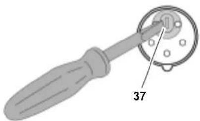
3. Plug power cable in again.
Protect power cable from heat, aggressive liquids and sharp edges.
Use only extension cables with sufficient lead cross section (see "Technical Specifications").
Do not stop the machine by unplugging, but switch OFF using the ON/OFF switch.
Unplug after use.
4.2 Installation
The device's installation location must meet the following requirements:
Dry, cool, protected from frost
Firm, horizontal and level surface

Danger!
Severe accidents may arise due to incorrect installation.
- Secure the device against rolling away and tipping over.
- Do not pull the device by the hose or power supply cable.
- Safety devices and operating elements must be easily accessible at all times.
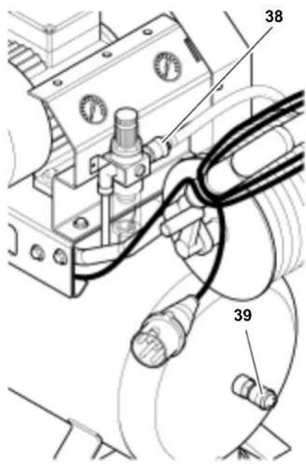
4.3 Generating compressed air
- Connect air hose to compressor. Depending on the purpose of application two outlets are available.
Air outlet for regulated, filtered compressed air (38).
Air outlet for non-regulated, unfiltered compressed air (39).
- Start compressor (40) and wait until the max. tank pressure is reached (compressor shuts off).
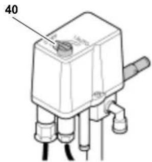
The tank pressure is indicated by the tank pressure gauge (41).
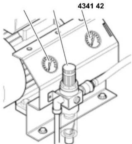
- Set pressure regulator (42) to required working pressure. The current working pressure is indicated by the regulated pressure gauge (43).
Caution!
Before connecting an air tool, make sure the max. operating pressure of the air tool used is not exceeded!
- Connect air tool to the compressor's air hose. You are now ready to work with the air tool.
- Switch the compressor OFF, if you do not continue working immediately afterwards. Unplug after switching OFF.
5. Care and Maintenance

Danger!
Prior to all servicing:
- Switch Off.
- Unplug.
- Wait until the compressor has come to a complete stop.
- Ensure the compressor and all air tools and accessories connected to it are relieved from pressure.
After all servicing:
- Check to see that all safety devices are operational.
- Make sure that no tools or other parts remain on or in the machine.
Repair and maintenance work other than described in this section must only be carried out by qualified specialists.
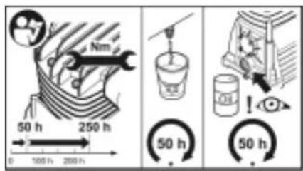
5.1 Periodic maintenance

Caution!
After the first 50 and 250 hours of operation, check the cylinder head's bolts tightening torque (see "Technical Specifications") of a new compressor pump.
Notes for commercial operation:
- Draw up an inspection and maintenance schedule which gives consideration to operating factors such as installation or operating mode. In this, provide for regular checks by an authorised person.
The supervisory authority may demand the submission of the inspection and maintenance schedule and proof of the checks which have been carried out.
A sample template can be requested from the Service Centre in your country. See spare parts list for address.
Prior to each use
- Check air hoses for damage, replace if necessary.
- Check all screwed connections for tightness, tighten if necessary.
- Check power supply cable for damage, if necessary have replaced by a qualified electrician.
Every 50 operating hours
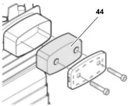
- Check air filter element (44) of compressor pump, clean if necessary.
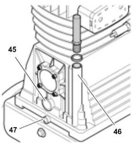
- Check oil level (45) of compressor pump, top up if necessary (46).
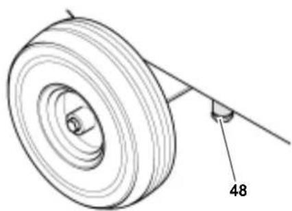
- Drain the condensation water from the pressure vessel into a container (48). Tip or lift the unit if necessary.
The condensation water contains oil residues. Dispose of the condensation water in an environmentally friendly manner to the appropriate collection points!
- Clean the seal and thread of the screw connection prior to reinsertion.
Clean air filter element (49) of filter/ regulator unit.
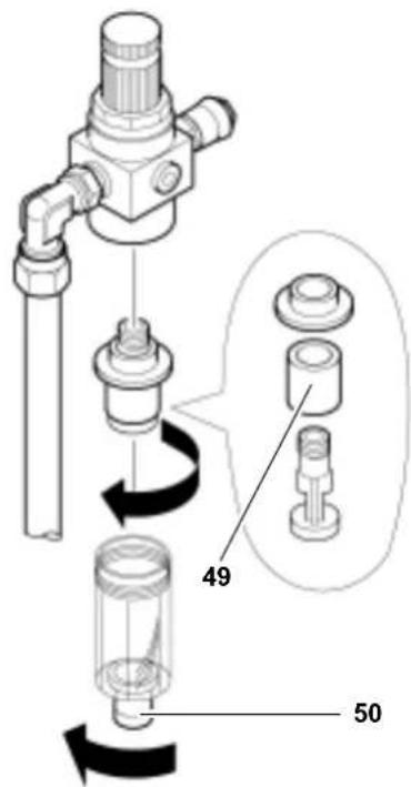
-
Drain condensate from filter/regulator unit (50).
-
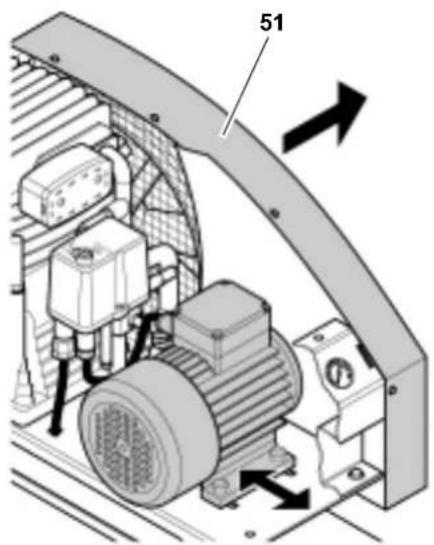
Check V-belt:
-
Remove belt guard (51).
- Retension V-belt or replace, if necessary.
- To adjust the V-belt tension, loosen the four screws at the motor base and shift the motor.
- Tighten the screws at the motor base again.
- Replace the belt guard.
Every 250 operating hours
- Replace air intake filter element of compressor pump.
- Replace air filter element of filter/regulator unit.
Every 500 operating hours
- Drain oil from compressor pump through the drain plug (47) and fill with fresh oil.
! Dispose of the waste oil environ-. mentally safe by taking it to a proper collecting point!
Every 1000 operating hours
- Have unit serviced by an authorized service station. This will extent the compressor's service life considerably.
5.2 Machine storage
- Switch unit OFF and unplug.
- Release pressure from tank and all connected air tools.
- Store machine in such way that it cannot be started by unauthorized persons.
#
Caution!
Do not store machine unprotected outdoors or in damp environment. Do not lay machine on its side for transportation or storing.
6. Available Accessories
For special applications the following accessories are available at your specialist dealer - see back cover for illustrations:
Sealing
A Air Caulking Gun KP 910 for commercially available cartridges. Stock-no.090 101 0030
Sheet metal cutting
B Air Nibbler BN 540 extra small cutting radius; cuts steel sheet up to 1.0mm thickness. Stock-no.0901006784
Drilling
C Air Drill BM 310 especially handy tool for low-fatigue working; right-hand rotation only. Stock-no.090 100 6725
Air Drill BM 500 (not shown) with 3 / 8'' keyless chuck, fully reversible with quick reverse feature. Stock-no.0901054533
Stapling / nailing
D Combination Air Stapler/Nailer Kombi 40/50 for staples (type 90) from 20mm to 40~mm and finishing nails (type SKN) from 20mm to 50~mm . Stock-no. 090 105 4720
Combination Air Stapler/Nailer Kombi 32 (not illustrated) for staples (type 90) from 15mm to 32mm and finishing nails (type SKN) from 16mm to 32mm . Stock-no. 090 105 4711
Air Stapler KG 80/16 (not illustrated) for staples (type 80) from 6 mm to 16 mm. Stock-no. 090 105 4681
Air Stapler KG 90/25 (not illustrated) for staples (type 90) from 15mm to 25mm . Stock-no. 090 105 4690
Air Stapler KG 90/40 (not illustrated) for staples (type 90) from 20mm to 40~mm Stock-no.0901054703
Air Finish Nailer SKN 50 (not illustrated) for finishing nails (type SKN) from 20mm to 50mm . Stock-no. 090 105 4738
Spray painting
E Spray Gun FB 2200 HVLP High-volume low-pressure feature reduces paint mist bounce-back and provides thicker coating at less paint consumption. Stock-no.0901054460
- Paint Spray Gun FB 2200 (not illustrated) with 0.5 l flow cup; professional spray gun; stepplessly adjustable round, horizontal and vertical spray pattern. Stock-no. 090 105 4452
- Paint Spray Gun SB 200 (not illustrated) with 1.0 l siphon cup. Stock-no. 090 100 3882
- Paint Spray Gun FB 150 (not illustrated) with 0.5 I flow cup; for spraying primers and paints of varying viscosity. Stock-no. 090 100 3874
- Paint Spray Gun FB 90 (not illustrated) with 0.75 l flow cup; for spraying primers and paints of varying viskosity. Stock-no. 090 105 6064
Chiselling
F Air Hammer Set MHS 450 for construction and auto body work Stock-no.0901009210
Air Hammer Set MHS 315 (not illustrated) to take off plaster and tiles and for light chiselling work. Stock-no.090 1006911
Tyre inflating / checking
G Tyre Inflator Gauge RF 480 professional version (calibrated). Stock-no.0901054630
Tyre Inflator Gauge RF 363 (not illustrated) same as RF 480, but not calibrated. Stock-no. 090 105 4622
Tyre Inflator Gauge RF 200 (not illustrated) for inflating tyres and balls (calibrated). Stock-no.0901056188
Tyre Inflator Gauge RF 100 (not illustrated) same as RF 200, but not calibrated. Stock-no. 090 102 6724
Cleaning
H Blow Gun BP 200 all plastic body. Stock-no.0901054606
- Blow Gun BP 300 (not illustrated) all plastic body; venturi nozzle provides extra high air volume. Stock-no. 090 105 4614
- Blow Gun BP 70 (not illustrated) light metal body (with 100mm extension nozzle). Stock-no. 090 102 6726
- Blow Gun BP 60 (not illustrated) light metal body (short). Stock-no. 090 102 6718
Driving screws
I Impact Wrench SR 230 rugged impact wrench for DIY and automotive applications. Stock-no.0901056170
- Impact Wrench SR 340 Set (not illustrated) professional version; many accessories included. Stock-no. 090 105 6137
- Impact Wrench SR 140 Set (not illustrated) for multiple DIY and automotive applications; complete with many accessories. Stock-no. 090 100 8582
- Impact Wrench SR 120 Set (not illustrated) requires only minimal amount of air, thus can be run on small compressors; complete with many accessories. Stock-no. 090 100 6750
- Ratchet Wrench RS 320 (not illustrated) due to narrow design and rubber-covered ratchet head it is well suited for automotive applications and work in confined areas. Stock-no. 090 105 4541
- Ratchet Wrench RS 220 Set (not illustrated)
this set comes complete with many accessories.
Stock-no. 090 100 6717
Air Screwdriver DS 1610 (not illustrated) reversible with quick reversing action. Stock-no.090 101 2440
Spraying
J Spray Gun SPP 161 for spraying degreaser, oil, liquid wax, etc. Stock-no.090 1054525
Combination Spray Gun UBS 820 (not illustrated) for commercially available 1.0 I screw-top cartridges. Stock-no. 090 105 4479
Air hoses
K Hose Reel ST 200 swivels through 360^ with 30mPU air hose. Stock-no.0901054568
Braided Air Hose (not illustrated) c/w quick coupler and male plug; length 5 m; outer diameter 12 mm inner diameter 6 mm. Stock-no.090 105 4908
Braided Air Hose (not illustrated) c/w quick coupler and male plug; length 10 m outer diameter 12 mm inner diameter 6 mm. Stock-no.090 1054916
- Braided Air Hose (not illustrated)
c/w quick coupler and male plug;
length 10 m; outer diameter 15 mm;
inner diameter 9 mm.
Stock-no. 090 105 4924
- Bulk Braided Air Hose (not illustrated)
length 50 m; outer diameter 15 mm; inner diameter 9 mm.
Stock-no. 090 105 4932
Self-storing Coil Air Hose, Rilsan (not illustrated) c/w quick coupler and male plug; 2.5m working length; outer diameter 8 mm inner diameter 6 mm. Stock-no.0901054940
Self-storing Coil Air Hose, Rilsan (not illustrated) c/w quick coupler and male plug; 7.5m working length; outer diameter 8 mm inner diameter 6 mm. Stock-no.0901054959
Self-storing Coil Air Hose, Rilsan (not illustrated) c/w quick coupler and male plug; 10.0m working length; outer diameter 10mm inner diameter 8mm Stock-no.090 1054967
Hand-crank Hose Reel SA 100 (not illustrated) c/w 20.0m braided air hose; outer diameter 15mm ; inner diameter 9mm . Stock-no. 090 105 4975
Automatic Retractable Hose Reel SA 200 (not illustrated) suitable for wall and ceiling mounting; retracts automatically by simply pulling on hose; with 8m PU air hose; outer diameter 13mm ; inner diameter 8mm . Stock-no. 090 105 4550
Accessory kits
L Accessory Kit LPZ 7-S comprising: Blow gun, tyre inflator gauge, tyre valve nozzle, needle tip nozzle, paint spray gun, spray gun, self-storing coil air hose. Stock-no.0901003858
- Accessory Kit LPZ 7-P (not illustrated) comprising: Blow gun, tyre inflator gauge, tyre valve nozzle, needle tip nozzle, paint spray gun, spray gun, 10m braided air hose. Stock-no. 090 100 3890
- Accessory Kit LPZ 6 (not illustrated) comprising: Blow gun, tyre inflator gauge, tyre valve nozzle, needle tip nozzle, paint spray gun, 5m braided air hose. Stock-no.0901044487
- Accessory Kit LPZ 4 (not illustrated) comprising: Blow gun, tyre inflator gauge, paint spray gun, self-storing coil air hose.
Stock-no. 090 101 3845 - Accessory Kit LPZ 2 (not illustrated) contains change handle with blow gun, tyre inflator gauge, paint spray gun, self-storing coil air hose. Stock-no.0901055971
7. Trouble Shooting
Danger!
Prior to all servicing:
- Switch Off.
- U npIug.
- Wait until the compressor has come to a complete stop.
- Ensure the compressor and all air tools and accessories connected to it are relieved from pressure.
After all servicing:
- Check to see that all safety devices are operational.
- Make sure that no tools or other parts remain on or in the machine.
Compressor does not run:
No mains voltage.
- Check cables, plug, outlet and mains fuse.
- Mains voltage too low.
- Use only extension cables with sufficient lead cross section (see "Technical Specifications"). Avoid using extension cable with cold machine.
- Compressor was stopped by unplugging.
- Switch compressor OFF at the On/Off switch, then ON again.
- Motor has overheated, caused by insufficient cooling (cooling fins covered).
- Remove cause for overheating and allow to cool down for approx. 10 minutes, then start again.
Compressor runs but does not build up sufficient pressure.
- Drain cock on cup of filter/regulator unit open.
- Close drain cock.
- Check valve leaky.
- Have check valve serviced by qualified service centre.
Air tool is not supplied with sufficient pressure.
Pressure regulator not opened wide enough.
- Open pressure regulator more.
- Hose connection between compressor and air tool leaky.
- Check air hoses, replace defective parts if necessary.
8. Repairs
Danger!
Repairs to electric tools must be carried out by qualified electricians only!
Electric tools in need of repair can be send to the service centre in your country. See spare parts list for address.
Please attach a description of the fault to the electric tool.
9. Environmental protection
The machine's packaging can be 100% recycled.
Worn out machines and accessories contain considerable amounts of valuable raw and plastic materials, which can be recycled.
These instructions are printed on chlorine-free bleached paper.
10. Technical Specifications
| Suction capacity l/min 480 | ||
| Free air delivery (volume flow rate) l/min 330 | ||
| Filling rate l/min 370 | ||
| Working pressure (compression end pressure) bar 10 | ||
| Pressure vessel volume l 90 | ||
| No. of air outlets 2 | ||
| Maximum outlet temperature | 40 K higher than ambient temperature | |
| Compressor pump model B4900 / 4900 B | ||
| No. of cylinders 2 | ||
| Cylinder head bolt tightening torque | Nm | 23 - 27 |
| Speed (compressor pump) | min-1 | 1275 |
| Motor capacity | kW | 3.0 S1 |
| Supply voltage (50 Hz) | V | 400 |
| Rated current | A | 6.2 |
| Fuse protection min. | A | 10 (time-lag) |
| Degree of protection | IP 54 | |
| Max. overall cable length when using extension cables: | ||
| - at 3 x 1.0 mm² lead cross section | m | 15 |
| - at 3 x 1.5 mm² lead cross section | m | 25 |
| - at 3 x 2.5 mm² lead cross section | m | 40 |
| Oil grade (compressor pump) | SAE 40 | |
| Required oil quantity (compressor pump) | I | 1.1 |
| Dimensions length x width x height | mm | 1230 x 560 x 910 |
| Weight | kg | 93,5 |
| Sound pressure level LPA at 4 m max. | dB (A) | 73 ± 3 |
| Sound power level LWA | dB (A) | 93 |