1956521 - Multifunction tool MAKITA - Free user manual and instructions
Find the device manual for free 1956521 MAKITA in PDF.

| Product type | Brush cutter head for multifunction tool |
| Brand | Makita |
| Model | 1956521 (compatible EM400MP, EM401MP) |
| Dimensions (L x D x H) | EM400MP : 876 x 374 x 211 mm ; EM401MP : 907 x 310 x 220 mm |
| Net weight | 1.0 kg (without guard or blade) |
| Power source | By approved power unit (gasoline or electric) – EX2650LH |
| Metal blade diameter | 230 mm |
| Plastic blade diameter | 255 mm (optional) |
| Cutting diameter (nylon line head) | EM400MP : 420 mm ; EM401MP : 300 mm |
| Nylon line diameter | EM400MP : 2.4 mm ; EM401MP : 2.7 mm |
| Speed ratio | 14/19 |
| Main functions | Cutting grass, weeds, bushes, undergrowth |
| Maximum permitted speed | 6,000 min⁻¹ (for line extension) |
| Safety | Blade guard, mandatory engine stop before maintenance, safety distance 15 m, protective equipment (helmet, glasses, gloves, boots) |
| Maintenance | Lubrication every 30 h (gear case and shaft), replace blade/line if worn, sharpening by authorized center |
| Spare parts and repairability | Genuine Makita parts, maintenance by authorized center, metal/plastic blade, nylon head, guard |
| Operating temperature | -10°C to 40°C (estimate) |
| Noise level | Not specified in the manual |
| Package contents | Brush cutter head, guard, cutting tool (blade or line head), instruction manual |
| Compliance | CE (2006/42/CE, 2000/14/CE), EN ISO 11806-1:2011, EN 50636-2-91:2014 |
| Warranty | Consult Makita warranty (1 year standard, depending on country) |
Frequently Asked Questions - 1956521 MAKITA
User questions about 1956521 MAKITA
0 question about this device. Answer the ones you know or ask your own.
Ask a new question about this device
Download the instructions for your Multifunction tool in PDF format for free! Find your manual 1956521 - MAKITA and take your electronic device back in hand. On this page are published all the documents necessary for the use of your device. 1956521 by MAKITA.
USER MANUAL 1956521 MAKITA
natural_image
Technical line drawing of two mechanical lever arms (no text or symbols)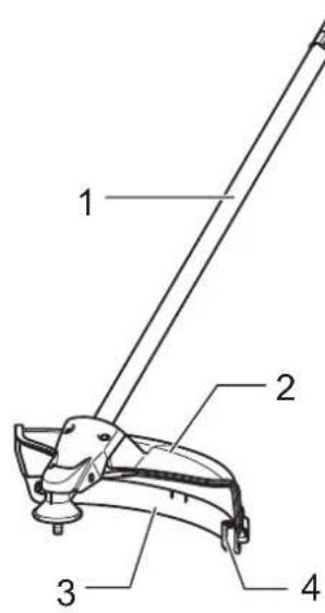
EM400MP
EM401MP
1
natural_image
Illustration of a person wearing safety gear and four different footprints (shoes, gloves, shoes) arranged around it, with no text or symbols present.2
natural_image
Line drawing of a person using a handheld device to adjust or install a mechanical component (no text or symbols present)3
natural_image
Line drawing of a person holding a rope and cable, no text or symbols present4
5
6
natural_image
Technical line drawing of a mechanical part with two views: one showing a cross-shaped component and the other showing a shoe (no text or symbols)7
8
9
10
natural_image
Line drawing of a shoe with labeled component G and directional arrow (no text or symbols beyond label)11
12
13
14
natural_image
Technical line drawing of a mechanical component with an arrow indicating rotation (no text or symbols)15
16
17
18
natural_image
Diagram of a mechanical component with directional arrows indicating flow or movement (no text or symbols)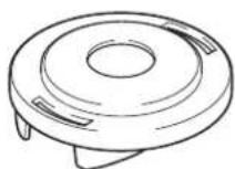

natural_image
Diagram of a mechanical component with a cylindrical body and two wires, no text or symbols present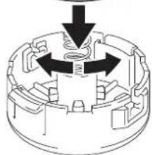
natural_image
Mechanical component diagram showing a central shaft with three directional arrows indicating rotation or force (no text or symbols)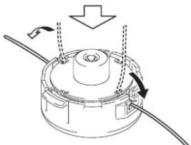
natural_image
Diagram of a mechanical component with arrows indicating motion or force direction (no text or symbols)
natural_image
Technical line drawing of a mechanical assembly with no visible text or symbols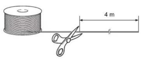
natural_image
Diagram of a mechanical component with directional arrows indicating flow or movement (no text or symbols)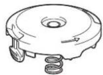

natural_image
Cross-sectional diagram of a mechanical component with internal structure and an arrow indicating direction (no text or symbols)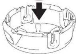
natural_image
Technical line drawing of a mechanical component with a downward arrow indicating a feature (no text or symbols present)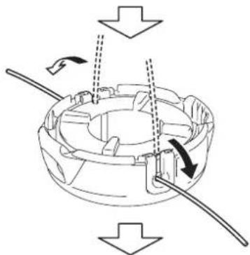
natural_image
Mechanical assembly diagram showing a rotating component with arrows indicating motion (no text or symbols)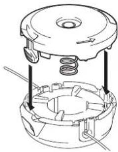
natural_image
Technical diagram of a mechanical assembly showing internal components and a central housing (no text or labels)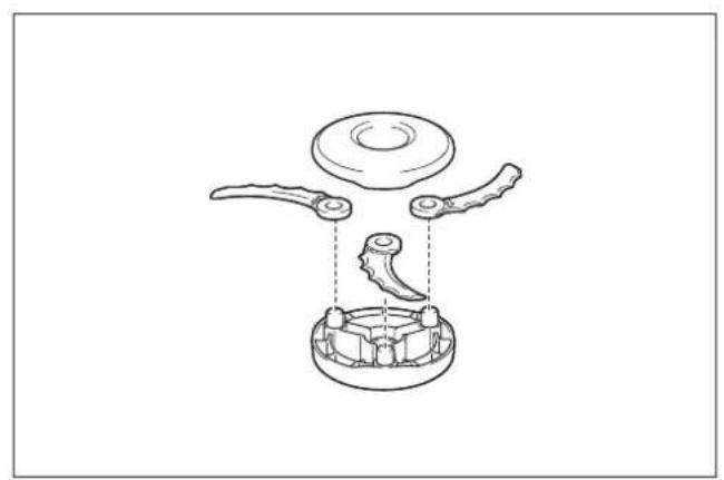
natural_image
Technical line drawing of a mechanical assembly with three components and a central housing (no text or symbols)21
22
natural_image
Line drawing of a hand holding a small electronic device with a handle (no text or symbols)23
natural_image
Line drawing of a hand holding a tool, poised to write on a surface (no text or symbols present)24
natural_image
Diagram showing a cylindrical device being inserted into a rod, with an arrow indicating the process (no text or symbols present)25
English
(Original instructions)
Contents
Page
Contents 8
Foreword 8
Symbols 8
Approved power unit....9
Part description....9
Safety precautions....9
Assembly and adjustment 10
Installing plastic blade ....11
Operation....11
Inspection and maintenance.... 12
Storage....12
Maintenance schedule.... 13
Troubleshooting....13
Technical Data....13
EC Declaration of Conformity....14
Declaration of Conformity (For UK) 14
Foreword
Thank you very much for purchasing Makita brushcutter attachment. This attachment is designed to be mounted on Makita power unit mentioned in this instruction manual.
Before use, please read this booklet and the instruction manual of the power unit. They will assist you to obtain the best possible result from your Makita brushcutter attachment.
Symbols
The following symbols are used on the attachment and this instruction manual. Understand these definitions.


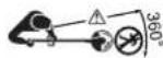


Take particular care and attention.
Read instruction manual.
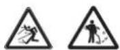
Danger; be aware of thrown objects.
The distance between the tool and bystanders must be at least 15 m.
Keep bystanders away.
Keep distance at least 15 m.
Avoid kickback.
Wear a helmet, goggles and ear protection.
Wear protective gloves.
Wear sturdy boots with nonslip soles. Steeltoed safety boots are recommended.
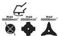
Top permissible tool speed.
Forbidden!
First Aid
(For European countries only) This product complies with EC directives.
Approved power unit
This attachment is approved to use only with the following power unit(s):
For EM400MP
EX2650LH Multi function power head
For EM401MP
EX2650LH Multi function power head
BUX360, BUX361, BUX362, UX360D, UX361D, UX362D, DUX60, UX01G
Cordless multi function power head
WARNING:
Never use the attachment with non-approved power unit. Non-approved combination may cause serious injury.
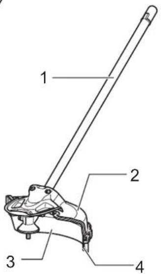
Part description (Fig. 1)
The numbers below refer to the figure.
- Shaft
- Protector (Cutting tool guard)
- Protector extension
- Cord cutter
Safety precautions
WARNING:
Read all safety warnings and all instructions in this booklet and the instruction manual of the power unit. Failure to follow the warnings and instructions may result in electric shock, fire and/or serious injury.
Save all warnings and instructions for future reference.
The term “brushcutter” and “equipment” in the warnings and precautions refer to the combination of the attachment and the power unit.
The term “motor” in the warnings and precautions refers to the engine or electric motor of the power unit.
Intended use
- This attachment is designed only for the purpose of cutting grass, weed, bushes and undergrowth in conjunction with an approved power unit. Never use the attachment for the other purpose.
Abusing the attachment may cause serious injury.
General precautions
- Before starting the brushcutter, read this booklet and the instruction manual of the power unit to become familiar with the handling of the brushcutter.
- Do not lend the attachment to a person with insufficient experience or knowledge regarding handling of brushcutters.
- When lending the attachment, always attach this instruction manual.
- Do not allow children or young persons under 18 years old to use the brushcutter. Keep them away from the brushcutter.
- Handle the brushcutter with the utmost care and attention.
- Never use the brushcutter after consuming alcohol or drugs, or if feeling tired or ill.
- Never attempt to modify the attachment.
- Follow the regulations about handling of brushcutters in your country.
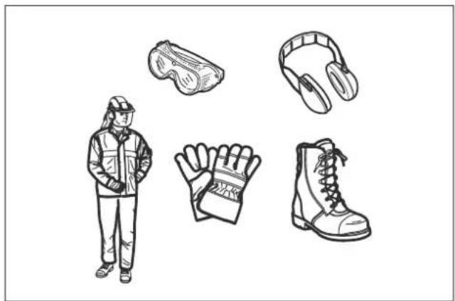
Personal protective equipment
- Wear safety helmet, protective goggles and protective gloves to protect yourself from flying debris or falling objects. (Fig. 2)
- Wear ear protection such as ear muffs to prevent hearing loss.
- Wear proper clothing and shoes for safe operation, such as a work overall and sturdy, non-slip shoes. Do not wear loose clothing or jewelry. Loose clothes, jewelry or long hair can be caught in moving parts.
- When touching the cutting blade, wear protective gloves. Cutting blades can cut bare hands severely.
Work area safety
- Operate the equipment under good visibility and daylight conditions only. Do not operate the equipment in darkness or fog.
- Do not use the machine in bad weather conditions especially when there is a risk of lightning.
- Start and operate the engine only outdoors in a well ventilated area. Operation in a confined or poorly ventilated area can result in death due to suffocation or carbon monoxide poisoning.
- During operation, never stand on an unstable or slippery surface or a steep slope. During the cold season, beware of ice and snow and always ensure secure footing.
- During operation, keep bystanders or animals at least 15 m away from the equipment. Stop the motor as soon as someone approaches.
- Never operate the machine while people, especially children, or pets are nearby.
- Before operation, examine the work area for stones or other solid objects. They can be thrown or cause dangerous kickback and result in serious injury and/or property damage.
- WARNING: Use of this product can create dust containing chemicals which may cause respiratory or other illnesses. Some examples of these chemicals are compounds found in pesticides, insecticides, fertilizers and herbicides.
Your risk from these exposures varies, depending on how often you do this type of work. To reduce your exposure to these chemicals: work in a well ventilated area, and work with approved safety equipment, such as those dust masks that are specially designed to filter out microscopic particles.
Putting into operation
- Before assembling or adjusting the equipment, switch off the motor and remove the spark plug cap or the battery cartridge.
- Before handling the cutter blade, wear protective gloves.
- Before starting the motor, inspect the equipment for damages, loose screws/nuts or improper assembly. Sharpen blunt cutter blade. If the cutter blade is bent or damaged, replace it. Check all control levers and switches for easy action. Clean and dry the handles.
- Never attempt to start the motor if the equipment is damaged or not fully assembled. Otherwise serious injury may result.
- Adjust the shoulder harness and hand grip to suit the operator's body size.
Starting motor
- Wear the personal equipments before starting the motor.
- Start the engine at least 3 meters (10 feet) away from the fueling spot.
- Before starting the motor, make sure that there is no person or animal in the work area.
- When starting the engine or inserting a battery cartridge, keep the cutting tool clear of your body and other object, including the ground. It may rotate when starting and may cause injury or damage to the equipment and/or property.
- Place the equipment on firm ground. Maintain good balance and secure footing.
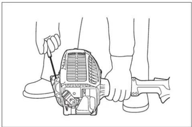
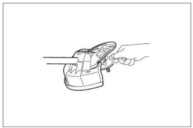
- When pulling the starter knob, hold the power unit firmly against the ground by your left hand. Never step on the drive shaft of the power unit. (Fig. 3)
- Follow the instruction manual of the power unit for starting the motor.
- If the cutting tool rotates at idle, stop the engine and adjust the idle speed down.
Operation
- In the event of an emergency, switch off the motor immediately.
- If you feel any unusual condition (e.g. noise, vibration) during operation, switch off the motor (and remove the battery cartridge in case of battery operated power unit). Do not use the equipment until the cause is recognized and solved.
- The cutting tool continues to rotate for a short period after releasing the throttle trigger or switch off the motor. Don't rush to contact the cutting tool.
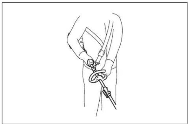
- With the engine running only at idle, attach the shoulder harness.
- During operation, use the shoulder harness. Keep the equipment on your right side firmly. (Fig. 4)
- Hold the front handle with the left hand and the rear grip with the right hand, no matter you are right-hander or left-hander. Wrap
your finger and thumbs around the handles.
- Never attempt to operate the equipment with one hand. Loss of control may result in serious or fatal injury. To reduce the risk of injury, keep your hands and feet away from the cutting tool.
- Do not overreach. Keep proper footing and balance at all times. Watch for hidden obstacles such as tree stumps, roots and ditches to avoid stumbling.
• Always be sure of your footing on slopes. - Walk, never run.
- Never work on a ladder or tree to avoid loss of control.
- If the equipment gets heavy impact or fall, check the condition before continuing work. Check the fuel system for fuel leakage and the controls and safety devices for malfunction. If there is any damage or doubt, ask Makita authorized service center for the inspection and repair.
- Do not touch the gear case. The gear case becomes hot during operation.
• Take a rest to prevent loss of control caused by fatigue. We recommend taking a 10 to 20-minute rest every hour. - When you leave the equipment, even if it is a short time, always switch off the engine or remove the battery cartridge. The equipment unattended with the engine running may be used by unauthorized person and cause serious accident.
- Follow the instruction manual of the power unit for proper use of the control lever and switch.
- During or after operation, do not put the hot equipment onto dry grass or combustible materials.
- If grass or branches get caught between the cutting tool and guard, always stop the motor and remove the spark plug cap or the battery cartridge before cleaning. Otherwise unintentional blade rotation may cause serious injury.
- Never touch moving hazardous parts before the machine is disconnected from the mains and the moving hazardous parts have come to a complete stop.
- If the cutting tool hits stones or other hard objects, immediately switch off the motor (and remove the battery cartridge in case of battery operated power unit) and inspect the cutting tool.
- Check the cutting tool frequently during operation for cracks or damages. Before the inspection, switch off the motor and wait until the cutting tool stops completely. Replace damaged cutting tool immediately, even if it has only superficial cracks.
- Never cut above waist height.
- Before starting the cutting operation, wait until the cutting tool reaches a constant speed after pulling the trigger.
- When using metal blades, swing the tool evenly in half-circle from right to left, like using a scythe.
Cutting tools
- Use an applicable cutting tool for the job in hand.
Nylon cutting heads (string trimmer heads) are suitable for trimming lawn grass.
Metal blades are suitable for cutting weeds, high grasses, bushes, shrubs, underwood, thicket, and the like. Never use other blades including metal multi-piece pivoting chains and flail blades. It may result in serious injury. - Always use the cutting tool guard properly suited for the cutting tool used.
- When using metal blades, avoid "kickback" and always prepare for an accidental kickback. See the section "Kickback."
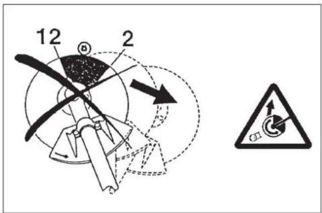
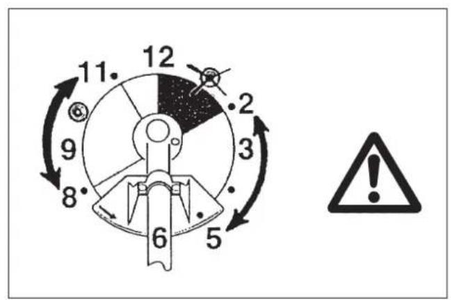
Kickback (Blade thrust) (Fig. 5 & 6)
- Kickback (blade thrust) is a sudden reaction to a caught or bound cutting blade. Once it occurs, the equipment is thrown sideway or toward the operator at great force and it may cause serious injury.
-
Kickback occurs particularly when applying the blade segment between 12 and 2 o'clock to solids, bushes and trees with 3 cm or larger diameter.
• To avoid kickback: -
apply the segment between 8 and 11 o'clock;
- never apply the segment between 12 and 2 o'clock;
– never apply the segment between 11 and 12 o'clock and between 2 and 5 o'clock, unless the operator is well trained and experienced and does it at his/her own risk;
– never use cutting blades close to solids, such as fences, walls, tree trunks and stones;
– never use cutting blades vertically, for such operations as edging and trimming hedges.
Vibration
- People with poor circulation who are exposed to excessive vibration may experience injury to blood vessels or the nervous system. Vibration may cause the following symptoms to occur in the fingers, hands or wrists: "Falling asleep" (numbness), tingling, pain, stabbing sensation, alteration of skin color or of the skin. If any of these symptoms occur, see a physician!
- To reduce the risk of "white finger disease", keep your hands warm during operation and well maintain the equipment and accessories.
Transport
- Before transporting the equipment, switch off the motor and remove the spark plug cap or battery cartridge. Attach the cover to the cutting blade.
- When transporting the equipment, carry it in a horizontal position by holding the shaft. Keep the hot muffler away from your body.
- When transporting the equipment in a vehicle, properly secure it to avoid turnover. Otherwise fuel spillage and damage to the equipment and other baggage may result.
Maintenance
- Have your equipment serviced by our authorized service center, always using only genuine replacement parts. Incorrect repair and poor maintenance can shorten the life of the equipment and increase the risk of accidents.
- Before doing any maintenance or repair work or cleaning the equipment, always switch off the motor and remove the spark plug cap or the battery cartridge. Wait until the motor gets cold.
- To reduce the risk of fire, never service the equipment in the vicinity of fire.
- Always wear protective gloves when handling the cutting blade.
- Always clean dust and dirt off the equipment. Never use gasoline, benzine, thinner, alcohol or the like for the purpose. Discoloration, deformation or cracks of the plastic components may result.
- After each use, tighten all screws and nuts, except for the carburetor adjustment screws.
- Do not attempt any maintenance or repair not described in this booklet or the instruction manual of the power unit. Ask Makita authorized service center for such work.
- Always use Makita genuine spare parts and accessories only. Using parts or accessories supplied by a third party may result in the equipment breakdown, property damage and/or serious injury.
- Request Makita authorized service center to inspect and maintain the equipment at regular interval.
Storage
- Before storing the equipment, perform full cleaning and maintenance. Remove the spark plug cap or the battery cartridge. Drain the fuel after the engine gets cold. Attach the cover to the cutting blade.
- Store the equipment in a dry and high or locked location out of reach of children.
- Do not prop the equipment against something, such as a wall. Otherwise it may fall suddenly and cause an injury.
First aid
• Always have a first-aid kit close by. Immediately replace any item taken from the first aid kit.
- When asking for help, give the following information:
- Place of the accident
- What happened
– Number of injured persons
– Nature of the injury - Your name
Assembly and adjustment
WARNING:
- Before assembling or adjusting the equipment, switch off the motor and remove the spark plug cap or battery cartridge. Otherwise the cutting tool or other parts may move and result in serious injury.
-
Before handling cutting blade, wear protective gloves. During the assembly or adjustment, your fingers may contact with the cutting blade and it may cause serious injury.
-
When assembling or adjusting the equipment, always put it down. Assembling or adjusting the equipment in an upright position may result in serious injury.
- Follow the warnings and precautions in the chapter "Safety precautions" and the instruction manual of the power unit.
Installing the protector
WARNING:
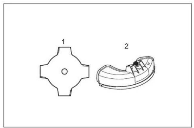
Never use the tool without the protector illustrated in place. Failure to do so can cause serious personal injury. (Fig. 7 & 8)
- Cutter blade
- Protector
- Nylon cutting head
- Protector extension
CAUTION:
Do not touch the cord cutter on the protector. Touching the cord cutter with bare hands may result in injury.
The protector must be installed to protect the operator from contact with the cutting tool and thrown stones and debris.
When using a nylon cutting head, the protector extension must also be installed to maintain the nylon-cutting-cord length.
Install the protector as the following steps.
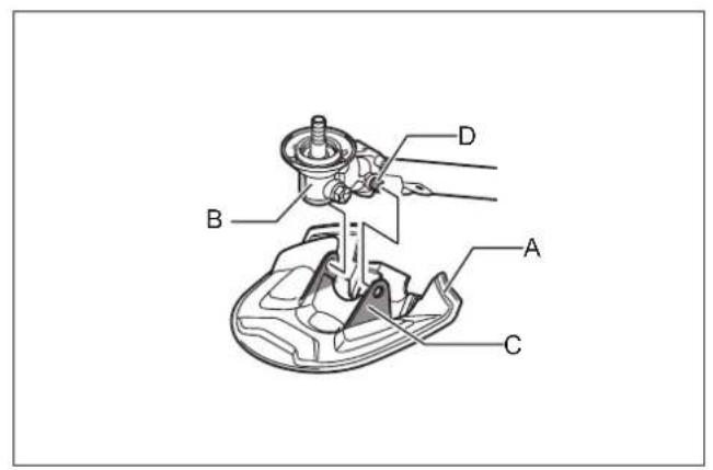
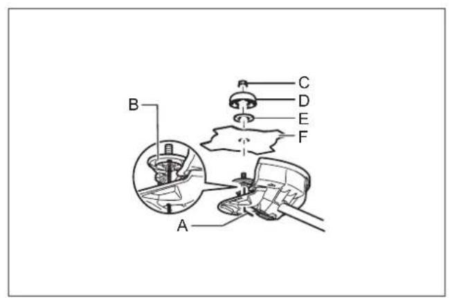
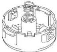
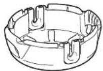
- Attach the protector cover (A) onto the gear case (B). Slightly push the wings (C) outward and put the bolts (D) into the holes in the wings. (Fig. 9)
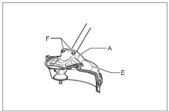
NOTICE: Do not push the wings outward too much. Otherwise it may break. - Fix the protector (E) to the protector cover (A) with two bolts (F). Tighten the right and left bolts evenly. (Fig. 10)
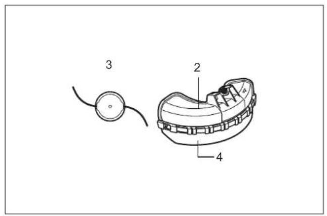
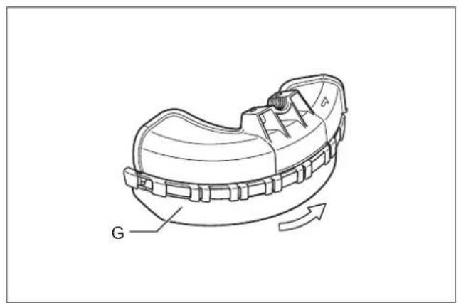
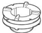
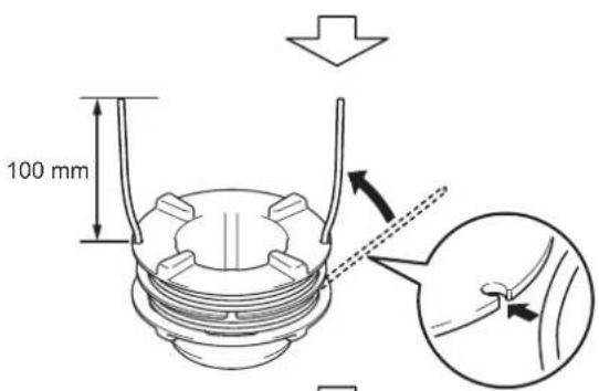
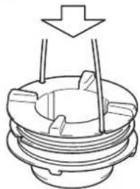
- When using a nylon cutting head, mount the protector extension (G). Place the protector extension onto the mounting track provided on the lower edge of the protector. Slide it into position until the protector extension clicks and locks into place. The protector extension is designed so that it will only mount onto the protector in one direction. (Fig. 11)
NOTE: Remove tape adhered to the cord cutter, which cuts nylon cord, on the protector extension at the first use.
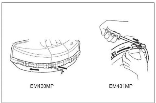
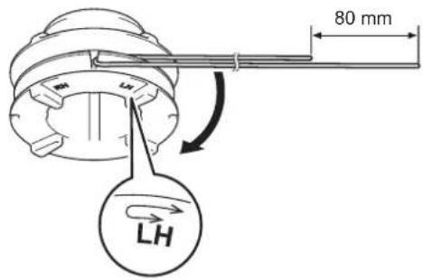
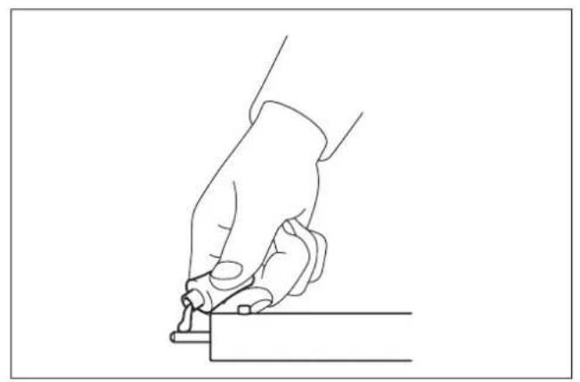
To remove the protector extension, place a hex wrench or flat-blade screwdriver into the small notch provided on the locking nub. Press down on the locking nub while sliding the lower protector extension in the direction indicated in the figure. Once the protector extension starts to slide, it is unlocked and can be removed by continuing to slide it off of the protector. (Fig. 12)
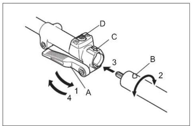
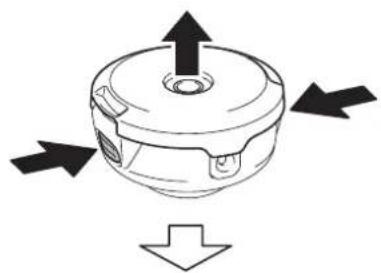
Mounting the attachment to a power unit (Fig. 13)
To mount the attachment to a power unit, follow the steps below.
-
Make sure that the lock lever (A) is not tightened.
-
Align the pin (B) with the arrow mark (C).
-
Insert the shaft into the drive shaft of the power unit until the release button (D) pops up.
-
Tighten the lock lever (A) firmly as shown. To remove the attachment, loosen the lock lever, press the lock button and withdraw the shaft.
NOTICE: Do not tighten the lock lever (A) without the shaft of the attachment inserted. Otherwise the lock lever may tighten the entrance of the drive shaft too much and damage it.
Removing and installing a cutter blade
WARNING:
- The outside diameter of the cutter blade must be 230 mm.
Never use any blade exceeding 230 mm in outside diameter.
CAUTION:
- The cutter blade must be well polished, free of cracks or breakage. Polish or replace the cutter blade every three hours of operation.
• Always wear gloves when handling the cutter blade. - Always attach the blade cover when the tool is not in use or is being transported.
- The cutter-blade fastening nut (with spring washer) is a consumable part. If there appears any wear or deformation on the spring washer, replace the nut. Ask your local authorized service center to order it.
NOTICE:
- Be sure to use genuine Makita cutter blade.
Turn the tool upside down so that you can replace the cutter blade easily. (Fig. 14)
- To remove the old cutter blade, insert the hex wrench (A) through the hole on the protector cover and gear case.
- Turn the receive washer (B) until it is locked by the hex wrench (A).
- Loosen the hex nut (C) clockwise with the socket wrench and remove the nut (C), cup (D), clamp washer (E) and old cutter blade (F).
- Attach the cutter blade (F) onto the shaft so that the guide of the receive washer (B) fits in the arbor hole in the cutter blade.
- Install the clamp washer (E) and cup (D). Tighten the hex nut (C) counterclockwise with 13 to 23 Nm of tightening torque during holding the receive washer (B) with hex wrench (A).
- Remove the hex wrench (A). Make sure that the blade is the left way up. (Fig. 15)
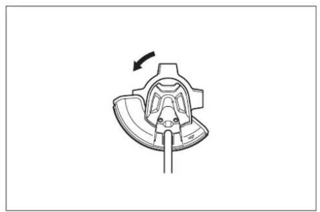
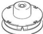
Removing and installing a nylon cutting head (Fig. 16)
CAUTION:
Do not touch the cord cutter on the protector. Touching the cord cutter with bare hands may result in injury.
- To remove the old nylon cutting head, insert the hex wrench (A) through the hole on the protector cover and gear case.
- Turn the receive washer (B) until it is locked by the hex wrench (A).
- Turn the old nylon cutting head (C) clockwise to loosen and remove it.
- Put a new nylon cutting head (C) onto the shaft. Turn it counterclockwise during locking the receive washer (B) with the hex wrench (A). Make sure that it is installed securely.
- Remove the hex wrench (A).
Installing plastic blade
Optional accessory
CAUTION: If the plastic blade accidentally impacts a rock or hard object during operation, stop the tool and inspect for any damage. If the plastic blade is damaged, replace it immediately. Use of a damaged cutting tool could result in serious personal injury.
CAUTION: Make sure to remove the hex wrench after installation.
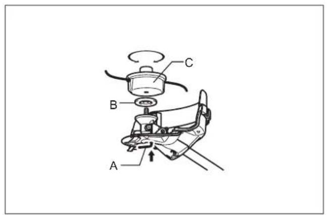
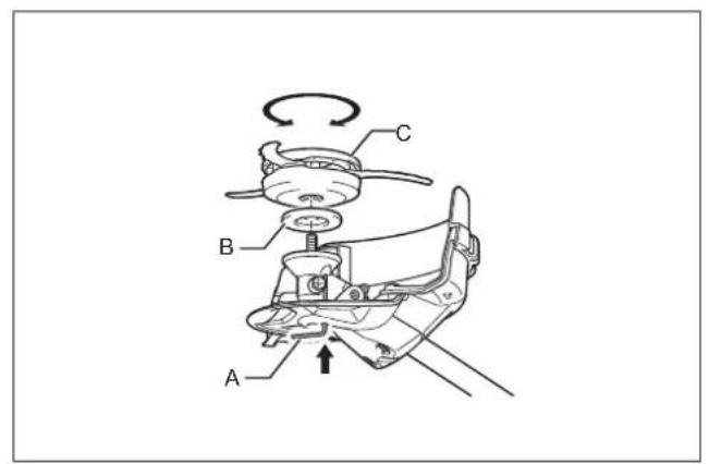
NOTICE: Be sure to use genuine Makita plastic blade. (Fig. 17)
- Turn the tool upside down so that you can replace the cutting tool easily.
- Insert the hex wrench (A) through the hole on the protector cover and gear case.
- Turn the receive washer (B) until it is locked by the hex wrench (A).
- Place the plastic blade (C) onto the shaft (threaded spindle) directly and tighten it by turning it counterclockwise.
- Remove the hex wrench.
To remove the plastic blade, turn it clockwise while holding the receive washer with the hex wrench.
Operation
WARNING:
- If the cutting tool moves at idle, adjust the idle speed of the engine down. Otherwise you cannot stop the cutting tool by throttle off and it may cause serious injury.
- Follow the warnings and precautions in the chapter "Safety precautions" and the instruction manual of the power unit.
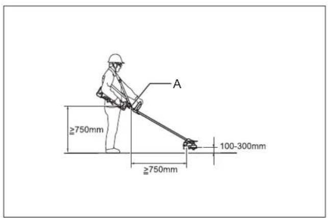
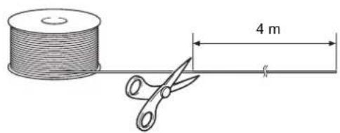
Adjusting the hanger position and shoulder harness (Fig. 18)
WARNING:
Do not use the tool if you cannot adjust the hanger position and shoulder harness length within the range as illustrated. Using the tool with improper weight balance may bring the cutting tool upward and result in personal injury.
When replacing an accessory with another, the weight balance of the equipment may change. In such case, adjust the hanger position and shoulder harness length as follows.
To change the hanger position, loosen the fixing screw on the hanger and then move the hanger (A).
Adjust the hanger position and shoulder harness length so that:
- the hanger positions 750~mm or higher from the ground,
- the cutting tool positions 100 mm to 300 mm high from the ground and
- the unguarded part of cutting tool is horizontally 750 mm or farther away from the hanger.
After adjusting the hanger position, tighten the screw with a wrench or screwdriver (depending on the power unit) securely.
Using a nylon cutting head
During operation, use the tip of the nylon cutting cord for cut. As the nylon cutting cord is worn and shortened with the cutting operation, the operator needs to feed it manually.
To feed the nylon cutting cord, tap the nylon cutting head on the ground while it rotates around 6,000 min ^-1 .
NOTE:
- If the nylon cutting cord does not feed out, rewind it. Refer to the chapter "Inspection and maintenance."
Inspection and maintenance
WARNING:
- Before inspecting or maintaining the equipment, switch of the motor and remove the spark plug cap or battery cartridge.
Otherwise the cutting tool or other parts may move and result in serious injury. - When inspecting or maintaining the equipment, always put it down. Assembling or adjusting the equipment in an upright position may result in serious injury.
- Follow the warnings and precautions in the chapter "Safety precautions" and the instruction manual of the power unit.
Resharpening the cutting tool
WARNING:
Do not resharpen cutting blades by yourself. Manual resharpening unbalances a cutting blade and it can cause vibrations and damage to the equipment.
Ask Makita authorized service center to resharpen and rebalance blunt cutter blades.
Replacing the nylon cord
WARNING:
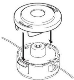
For the bump and feed type nylon cutting head, make sure that the cover of the nylon cutting head is secured to the housing properly as described below. Failure to properly secure the cover may cause the nylon cutting head to fly apart resulting in serious personal injury.
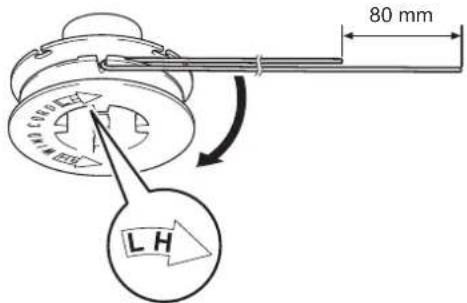
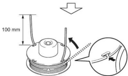
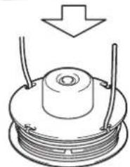
The way to replace the nylon cord varies depending on the cutting tool type. Replace the nylon cord if the cord is not fed any more.
For B&F 4 (Fig. 19)
For Bump & Feed type (Fig. 20)
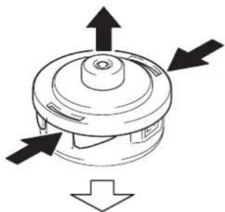
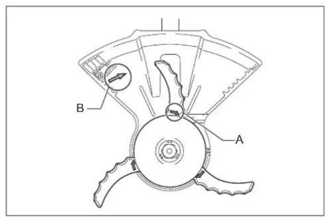
Replacing the plastic blade
Replace the blade if it is worn out or broken. (Fig. 21) When installing the plastic blade, align the direction of the arrow on the blade (A) with that of the protector (B). (Fig. 22)
Lubricating moving parts
NOTICE: Follow the instruction of the frequency and amount of grease supplied. Otherwise insufficient lubrication may damage moving parts.
Gear case:
Supply grease (Shell Alvania 2 or equivalent) to the gear case through the grease hole every 30 hours of operation. (Genuine Makita grease may be purchased from your local Makita dealer.)
(Fig. 23)
Drive axle:
Supply grease (Shell Alvania No.2 or equivalent) every 30 hours of operation. (Fig. 24)
Overall inspection
- Tighten loose bolts, nuts and screws.
- Check for damaged parts. Ask Makita authorized service center to replace them.
Storage
WARNING:
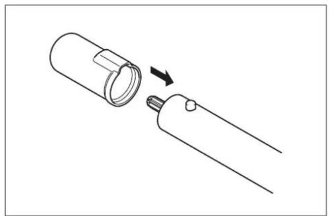
Follow the warnings and precautions in the chapter "Safety precautions" and the instruction manual of the power unit. (Fig. 25) When storing the brushcutter attachment separated from the power unit, put the cap onto the end of the shaft.
Maintenance schedule
| Operating hour | Before Operation | Daily (10h) 30h If required | Corresponding page | ||
| Whole unit Visually inspect for damaged parts | ○ | 12 | |||
| All fixing screws and nuts Tighten | ○ | 12 | |||
| Gear case Supply grease | ○ | 12 | |||
| Drive axle Supply grease | ○ | 12 | |||
| Cutter blade Visually inspect for damage | ○ | ○ | 12 | ||
| Power unit Refer to the instruction manual of the power unit | |||||
Troubleshooting
| Problem Probable caus Solution | ||
| The engine does not start. Refer to the instruction manual of the power unit. | ||
| The engine stops soon after its start. | ||
| The maximum speed is limited. | ||
| The cutting tool does not rotate.→ Stop the motor immediately! | The cutting tool is not tightened securely. Tighten the cutting tool securely. | |
| A twig is caught between the cutting tool and the protector. | Remove the foreign matter. | |
| The drive system does not work properly. Ask Makita authorized service center to inspect and repair it. | ||
| The unit vibrates abnormally.→ Stop the motor immediately! | The cutting tool is bent, worn or broken. Replace the cutting tool with new one. | |
| The cutting tool is not tightened securely. Tighten the cutting tool securely. | ||
| One end of nylon cutting cord has been broken and the nylon cutting head got unbalanced. | Feed the nylon cutting cord with tapping the nylon cutting head on the ground. | |
| The cutting blade is not fitted on the guide of the receive washer. | Install the cutting blade properly. | |
| The drive system does not work properly. Ask Makita authorized service center to inspect and repair it. | ||
| The cutting tool does not stop.→ Stop the motor immediately! | The power unit does not work properly. Refer to the instruction manual of the power unit. | |
| The nylon cutting cord does not feed. The cord is used up or tangled in the spool. Rewind the cord. | ||
| The nylon cutting cord is not cut off at the correct length. | The cord cutter on the protector is damaged or missing. | Ask Makita authorized service center to replace the cord cutter. |
| The cord extends past the protector. | Rewind the cord. | |
Technical Data
| Model | EM400MP | EM401MP | |
| Dimensions (L x W x H) | mm | 876 x 374 x 211 | 907 x 310 x 220 |
| Nylon cord diameter | mm | 2.4 | 2.7 |
| Net weight (Not including protector and blade) | kg | 1.0 | 1.0 |
| Cutting blade diameter (metal) | mm | 230 | 230 |
| Plastic blade diameter | mm | 255 | 255 |
| Cutting diameter with a nylon cutting head | mm | 420 | 300 |
| Gear ratio | 14/19 | ||
EC Declaration of Conformity
We as the manufacturers Makita Europe N.V.
Business address Jan-Baptist Vinkstraat 2
3070 Kortenberg
BELGIUM
Authorize Hiroshi Tsujimura for the compilation of the technical file and declare under our sole responsibility that the product(s);
Designation...... Brushcutter Attachment
Designation of Type(s)......EM400MP, EM401MP
Fulfills all the relevant provisions of 2006/42/EC
and also fulfills all the relevant provisions of the following EC/EU Directives: 2000/14/EC
and are manufactured in accordance with the following Harmonised Standards: EN ISO 11806-1:2011, EN 50636-2-91:2014
Place and date of declaration: Kortenberg, Belgium, 26.6.2019
Responsible person: Hiroshi Tsujimura

Director - Makita Europe N.V.
Declaration of Conformity (For UK)
We as the manufacturers Makita Europe N.V.
Business address Jan-Baptist Vinkstraat 2
3070 Kortenberg
BELGIUM
Authorize Hiroshi Tsujimura for the compilation of the technical file and declare under our sole responsibility that the product(s);
Designation...... Brushcutter Attachment
Designation of Type(s)......EM400MP, EM401MP
Fulfills all the relevant provisions of S.I. 2008/1597 (as amended)
and also fulfills all the relevant provisions of the following UK Regulations: S.I. 2001/1701 (as amended)
and are manufactured in accordance with the following Designated Standards: EN ISO 11806-1:2011, EN 50636-2-91:2014
Place and date of declaration: Kortenberg, Belgium, 1.7.2020
Responsible person: Hiroshi Tsujimura

Director - Makita Europe N.V.
Importer: Makita (UK) Limited, Michigan Drive, Tongwell, Milton Keynes, Buckinghamshire, MK15 8JD, UK
Français
(Instructions d'origine)
Sommaire
Page
Sommaire 15
Avant-propos 15
Symboles....15
BUX360, BUX361, BUX362, UX360D, UX361D, UX362D, DUX60, UX01G
Responsible : Hiroshi Tsujimura

BUX360, BUX361, BUX362, UX360D, UX361D, UX362D, DUX60, UX01G
BUX360, BUX361, BUX362, UX360D, UX361D, UX362D, DUX60, UX01G
Persona responsible: Hiroshi Tsujimura

Director - Makita Europe N.V.
Português
BUX360, BUX361, BUX362, UX360D, UX361D, UX362D, DUX60, UX01G
Batteridrevetmultifunktionelt
værktøjshoved
ADVARSEL: