DUX60 - Multifunction tool MAKITA - Free user manual and instructions
Find the device manual for free DUX60 MAKITA in PDF.

| Product Type | Cordless Multifunction Tool |
| Brand | Makita |
| Model | DUX60 |
| Rated Voltage | 36 V DC |
| No-load Speed (without accessory) | Low: 0 - 5,700 min⁻¹ Medium: 0 - 8,200 min⁻¹ High: 0 - 9,700 min⁻¹ |
| Overall Length | 1,011 mm |
| Net weight (without accessory) | 3.2 kg |
| Net weight (with accessory and battery) | 5.1 kg - 11.7 kg (depending on configuration) |
| Compatible Battery | BL1815N / BL1820B / BL1830B / BL1840B / BL1850B / BL1860B |
| Compatible Charger | DC18RC / DC18RD / DC18RE / DC18SD / DC18SE / DC18SF / DC18SH / DC18WC |
| Main Functions | Brush cutter, grass trimmer, hedge trimmer, pole saw, tiller, blower, pump, weed wacker, etc. (accessories sold separately) |
| Maintenance and Cleaning | Clean with a dry cloth; do not use gasoline, benzene, thinner, alcohol. Regularly check fastenings. |
| Safety | Safety lever, automatic stop in case of overload/overheating, electronic torque control, shoulder strap included |
| Spare Parts and Repairability | Optional accessories (heads, extension, etc.) available; repair by Makita authorized service center |
| General Information | Brushless motor; tool and battery protection system; speed indicator; reverse function |
Frequently Asked Questions - DUX60 MAKITA
User questions about DUX60 MAKITA
0 question about this device. Answer the ones you know or ask your own.
Ask a new question about this device
Download the instructions for your Multifunction tool in PDF format for free! Find your manual DUX60 - MAKITA and take your electronic device back in hand. On this page are published all the documents necessary for the use of your device. DUX60 by MAKITA.
USER MANUAL DUX60 MAKITA
natural_image
Technical line drawing of a precision measuring tool (no text or symbols)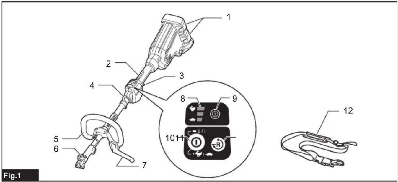
natural_image
Technical illustration of a mechanical device with labeled component '1' and directional arrow (no text or symbols beyond label)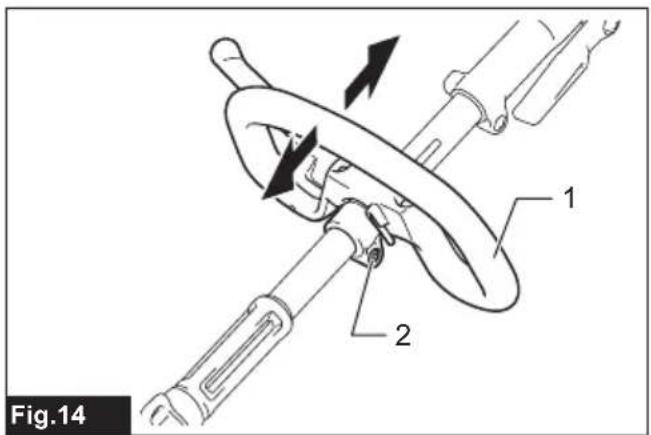

natural_image
Technical line drawing of a mechanical component with labeled part '1' (no text or symbols beyond label)SPECIFICATIONS
| Model: DUX60 | ||
| No load speed (without attachment) | Low 0 - 5,700 min | -1 |
| Medium 0 - 8,200 min | -1 | |
| High 0 - 9,700 min | -1 | |
| Overall length 1,011 mm | ||
| Rated voltage D.C. 36 V | ||
| Net weight *1 3.2 kg | ||
| *2 5.1 kg - 11.7 kg | ||
- Due to our continuing program of research and development, the specifications herein are subject to change without notice.
• Specifications may differ from country to country.
*1: Weight without any accessories or battery cartridge(s)
*2: The weight may differ depending on the attachment(s), including the battery cartridge. The lightest and heaviest combinations, according to EPTA-Procedure 01/2014, are shown in the table.
Applicable battery cartridge and charger
| Battery cartridge BL1815N / BL1820B / BL1830B / BL1840B / BL1850B / BL1860B | |
| Charger DC18RC / DC18RD / DC18RE / DC18SD / DC18SE / DC18SF /DC18SH / DC18WC |
- Some of the battery cartridges and chargers listed above may not be available depending on your region of residence.
WARNING: Only use the battery cartridges and chargers listed above. Use of any other battery cartridges and chargers may cause injury and/or fire.
Recommended cord connected power source
| Cord connected battery pack BL36120A | |
| Portable power pack PDC01 / PDC1200 / PDC1500* |
• The cord connected power source(s) listed above may not be available depending on your region of residence.
• Before using the cord connected power source, read instruction and cautionary markings on them.
* PDC1500 is not recommended for use with a blower attachment listed in "Approved attachment".
No load speed with attachment
| Model | Rotation speed | |||
| Low | Medium | High | ||
| EM401MP | 0 - 4,200 min^-1 | 0 - 6,000 min^-1 | 0 - 7,100 min^-1 | |
| EM404MP / EM406MP | 0 - 3,500 min^-1 | 0 - 5,000 min^-1 | 0 - 6,000 min^-1 | |
| EM407MP | Upper blade | 0 - 220 min^-1 | 0 - 310 min^-1 | 0 - 370 min^-1 |
| Lower blade | 0 - 470 min^-1 | 0 - 670 min^-1 | 0 - 790 min^-1 | |
| EM408MP / EM409MP | 0 - 4,200 min^-1 | 0 - 6,000 min^-1 | 0 - 7,100 min^-1 | |
| EN401MP / EN402MP / EN410MP / EN420MP / EN422MP / EN424MP(Strokes per minute) | 0 - 2,400 min^-1 | 0 - 3,400 min^-1 | 0 - 4,000 min^-1 | |
| EY403MP (chain speed) | 0 - 11 m/s | 0 - 16 m/s | 0 - 19 m/s | |
| KR400MP 0 - 160 min | ^-1 | 0 - 230 min^-1 | 0 - 280 min^-1 | |
| KR401MP 0 - 130 min | ^-1 | 0 - 190 min^-1 | 0 - 230 min^-1 | |
| EE400MP 0 - 2,800 min | ^-1 | 0 - 4,000 min^-1 | 0 - 4,700 min^-1 | |
| EJ400MP | 0 - 1,600 min^-1 | 0 - 2,300 min^-1 | 0 - 2,800 min^-1 | |
| Model Rotation speed | |||
| Low Medium | High | ||
| BR400MP 0 - 130 min | -1 | 0 - 190 min^-1 | 0 - 230 min^-1 |
| SW400MP 0 - 130 min | -1 | 0 - 190 min^-1 | 0 - 230 min^-1 |
| UB400MP 0 - 5,700 min | -1 | 0 - 7,850 min^-1 | 0 - 8,250 min^-1 |
| UB401MP 0 - 5,700 min | -1 | 0 - 7,850 min^-1 | 0 - 8,250 min^-1 |
| UB402MP 0 - 5,700 min | -1 | 0 - 8,100 min^-1 | 0 - 9,600 min^-1 |
| PF400MP 0 - 5,600 min | -1 | 0 - 8,100 min^-1 | 0 - 9,100 min^-1 |
| WA400MP 0 - 570 min | -1 | 0 - 815 min^-1 | 0 - 970 min^-1 |
| SN400MP 0 - 1,080 min | -1 | 0 - 1,560 min^-1 | 0 - 1,860 min^-1 |
Approved attachment
| Type Model | |
| Brushcutter attachment EM401MP / EM404MP | |
| String trimmer attachment EM406MP | |
| Rotary scissors attachment EM407MP | |
| Grass trimmer attachment EM408MP / EM409MP | |
| Hedge trimmer attachment EN401MP / EN402MP / EN410MP | |
| Ground trimmer attachment | EN420MP / EN422MP / EN424MP |
| Pole saw attachment | EY403MP |
| Cultivator attachment | KR400MP / KR401MP |
| Edger attachment | EE400MP |
| Coffee harvester attachment | EJ400MP |
| Shaft extension attachment | LE400MP |
| Power brush attachment | BR400MP |
| Power sweep attachment | SW400MP |
| Blower attachment | UB400MP / UB401MP / UB402MP |
| Pump attachment | PF400MP |
| Weeding attachment | WA400MP |
| Snow blower attachment | SN400MP |
Symbols
The followings show the symbols which may be used for the equipment. Be sure that you understand their meaning before use.


Read instruction manual.
Take particular care and attention.

Do not expose to moisture.

Ni-MH Li-ion
Only for EU countries
Due to the presence of hazardous components in the equipment, waste electrical and electronic equipment, accumulators and batteries may have a negative impact on the environment and human health.
Do not dispose of electrical and electronic appliances or batteries with household waste!
In accordance with the European Directive on waste electrical and electronic equipment and on accumulators and batteries and waste accumulators and batteries, as well as their adaptation to national law, waste electrical equipment, batteries and accumulators should be stored separately and delivered to a separate collection point for municipal waste, operating in accordance with the regulations on environmental protection.
This is indicated by the symbol of the crossed-out wheeled bin placed on the equipment.
Intended use
This cordless multi function power head is intended for driving an approved attachment listed in the section
"SPECIFICATIONS" of this instruction manual. Never
WARNING: Read the instruction manual of the attachment as well as this instruction manual before using. Failure to follow the warnings and instructions may result serious injury.
Noise
| Attachment Sound pressure level Guaranteed | sound power level | Measured sound power level | Applicable standard | ||||
| EM401MP (as a brushcutter) | 78.5 1.0 - 90.2 1 | 5 EN11806 | |||||
| EM401MP(as a string trimmer) | Nylon cuttinghead | 84.3 0.6 | -93.3 1.6 EN5 | 0636-2-91 | |||
| Plastic blade | 77.0 1.7 - 88.5 | 1.8 EN50636-2 | -91 | ||||
| EM404MP (as a brushcutter) | 82.5 2.2 - 93.3 2 | 9 EN11806 | |||||
| EM404MP(as a string trimmer) | Nylon cuttinghead | 84.7 2.3 | -92.8 1.6 EN5 | 0636-2-91 | |||
| Plastic blade | 76.0 1.8 - 87.7 | 1.5 EN50636-2 | -91 | ||||
| EM406MP Nylonon cuttinghead | 84.7 2.5 | -93.5 2.2 EN5 | 0636-2-91 | ||||
| 77.0 1.9 - 85.6 | 2.0 EN50636-2 | -91 | |||||
| EM407MP 83.2 3.9 - 99.3 2.5 ISO22868(ISO1)1806-1 | |||||||
| EM408MP (as a brushcutter) | 79.9 | 2.6 | - | 94.5 | 2.0 | ISO22868(ISO11806-1) | |
| EM408MP(as a string trimmer) | Nylon cuttinghead | 79.0 | 2.6 | - | 91.8 | 1.7 | ISO22868(ISO11806-1)/EN50636-2-91 |
| Plastic blade | 80.1 | 0.7 | - | 91.0 | 1.6 | ISO22868(ISO11806-1)/EN50636-2-91 | |
| EM409MP Nylonon cuttinghead | 79.9 | 2.3 | - | 92.7 | 0.9 | ISO22868(ISO11806-1)/EN50636-2-91 | |
| 80.3 | 0.9 | - | 91.2 | 2.2 | ISO22868(ISO11806-1)/EN50636-2-91 | ||
| EN401MP | 85 | 3 | 93 | 93 | 0.7 | EN62841-4-2 | |
| EN401MP + LE400MP | 82 | 3 | 94 | 93 | 1.1 | EN62841-4-2 | |
| EN402MP | 82 | 3 | 94 | 92 | 2.5 | EN62841-4-2 | |
| EN402MP + LE400MP | 79 | 3 | 95 | 93 | 1.9 | EN62841-4-2 | |
| EN410MP | 81 | 3 | 90 | 88 | 2.2 | EN62841-4-2 | |
| EN410MP + LE400MP | 79 | 3 | 91 | 88 | 2.7 | EN62841-4-2 | |
| EN420MP | 84 | 3 | 95 | 94 | 0.7 | EN62841-4-2 | |
| EN422MP | 81 | 3 | 93 | 91 | 1.8 | EN62841-4-2 | |
| EN424MP | 77 | 3 | - | 86 | 3 | EN62841-1 | |
| EY403MP | 96 | 3 | - | 105 | 3 | ISO22868(ISO11680-1) | |
| EY403MP+LE400MP | 96 | 3 | - | 105 | 3 | ISO22868(ISO11680-1) | |
| KR400MP | 76.7 | 2.2 | - | 84.2 | 1.0 | EN709 | |
| KR401MP | 73.1 | 1.4 | - | 84.2 | 1.8 | EN709 | |
| EE400MP | 74.8 | 1.5 | - | 88.2 | 2.6 | ISO11789 | |
| EJ400MP | 87.4 | 1.4 | - | 94.5 | 1.3 | ISO10517 | |
| EJ400MP + LE400MP | 85.6 | 1.0 | - | 95.5 | 1.3 | ISO10517 | |
| BR400MP | 79.5 | 0.9 | - | 89.0 | 0.7 | EN60335-2-72 | |
| SW400MP | 80.1 | 1.8 | - | 88.8 | 0.7 | EN60335-2-72 | |
| UB400MP | 89.8 | 0.4 | - | 100.4 | 0.8 | EN50636-2-100 | |
| UB401MP | 83.4 | 1.1 | - | 94.1 | 0.8 | EN50636-2-100 | |
| UB402MP | 80.5 | 1.6 | - | 90.2 | 1.7 | EN50636-2-100 | |
| Attachment Sound pressure level Guaranteed | sound power level | Measured sound power level | Applicable standard | |||
| L_pA (dB(A)) | Uncertainty K(dB(A)) | L_WA (dB(A)) L | W_A (dB(A)) | Uncertainty K(dB(A)) | ||
| PF400MP 72 3.9 - 87 3.9 ISO20361 | ||||||
| WA400MP | 74 | 3 | - | 88 | 3 | ISO22868(ISO11806-1) |
| SN400MP 77 3 - 91 2.2 ISO11201 / | ISO3744(ISO8437-4) | |||||
• Even if the sound pressure level listed above is 80 dB (A) or less, the level under working may exceed 80 dB (A). Wear ear protection.
NOTE: The declared noise emission value(s) has been measured in accordance with a standard test method and may be used for comparing one tool with another.
NOTE: The declared noise emission value(s) may also be used in a preliminary assessment of exposure.
Vibration
| Attachment | Left handle (Front grip) | Right handle (Rear grip) | Applicable standard | |||
| ah (m/s2) | Uncertainty K (m/s2) | ah (m/s2) | Uncertainty K (m/s2) | |||
| EM401MP (as a brushcutter) | 3.0 | 1.5 | ≤ 2.5 | 1.5 | EN11806 | |
| EM401MP (as a string trimmer) | Nylon cutting head | 5.0 | 1.5 | ≤ 2.5 | 1.5 EN506 | 36-2-91 |
| Plastic blade | ≤ 2.5 | 1.5 | ≤ 2.5 | 1.5 EN506 | 36-2-91 | |
| EM404MP (as a brushcutter) | 3.0 | 1.5 | ≤ 2.5 | 1.5 | EN11806 | |
| EM404MP (as a string trimmer) | Nylon cutting head | 3.0 | 1.5 | ≤ 2.5 | 1.5 EN506 | 36-2-91 |
| Plastic blade | ≤ 2.5 | 1.5 | ≤ 2.5 | 1.5 EN506 | 36-2-91 | |
| EM406MP | Nylon cutting head | 2.5 | 1.5 | ≤ 2.5 | 1.5 EN506 | 36-2-91 |
| Plastic blade | 4.0 | 1.5 | ≤ 2.5 | 1.5 EN506 | 36-2-91 | |
| EM407MP | ≤ 2.5 | 1.5 | ≤ 2.5 | 1.5 | ISO22867(ISO11806-1) | |
| EM408MP (as a brushcutter) | ≤ 2.5 | 1.5 | ≤ 2.5 | 1.5 | ISO22867(ISO11806-1) | |
| EM408MP (as a string trimmer) | Nylon cutting head | ≤ 2.5 | 1.5 | ≤ 2.5 | 1.5 | ISO22867(ISO11806-1) |
| Plastic blade | ≤ 2.5 | 1.5 | ≤ 2.5 | 1.5 | ISO22867(ISO11806-1) | |
| EM409MP | Nylon cutting head | ≤ 2.5 | 1.5 | ≤ 2.5 | 1.5 | ISO22867(ISO11806-1) |
| Plastic blade | ≤ 2.5 | 1.5 | ≤ 2.5 | 1.5 | ISO22867(ISO11806-1) | |
| EN401MP | 8.7 | 1.5 | 4.2 | 1.5 | EN62841-4-2 | |
| EN401MP + LE400MP | 5.9 | 1.5 | 4.4 | 1.5 | EN62841-4-2 | |
| EN402MP | ≤ 2.5 | 1.5 | 2.5 | 1.5 | EN62841-4-2 | |
| EN402MP + LE400MP | 4.4 | 1.5 | 2.7 | 1.5 | EN62841-4-2 | |
| EN410MP | 5.8 | 1.5 | 3.4 | 1.5 | EN62841-4-2 | |
| EN410MP + LE400MP | 4.6 | 1.5 | 2.8 | 1.5 | EN62841-4-2 | |
| EN420MP | 6.7 | 1.5 | 4.2 | 1.5 | EN62841-4-2 | |
| EN422MP | ≤ 2.5 | 1.5 | 2.6 | 1.5 | EN62841-4-2 | |
| EN424MP | ≤ 2.5 | 1.5 | ≤ 2.5 | 1.5 | EN62841-1 | |
| EY403MP | 2.7 | 1.5 | ≤ 2.5 | 1.5 | ISO22867(ISO11680-1) | |
| EY403MP+LE400MP | 3.0 | 1.5 | ≤ 2.5 | 1.5 | ISO22867(ISO11680-1) | |
| Attachment Left handle | (Front grip) Right handle (Rear grip) Applicable standard | ||||
| ah (m/s2) Uncertainty K(m/s2) | ah (m/s2) Uncertainty K(m/s2) | ||||
| KR400MP | ≤ 2.5 | 1.5 | ≤ 2.5 | 1.5 EN709 | |
| KR401MP | ≤ 2.5 | 1.5 | ≤ 2.5 | 1.5 EN709 | |
| EE400MP | ≤ 2.5 | 1.5 | ≤ 2.5 | 1.5 ISO11789 | |
| EJ400MP 4.0 1.5 3.0 1.5 ISO10517 | |||||
| EJ400MP + LE400MP 4.5 1.5 3.0 1.5 ISO10517 | |||||
| BR400MP | ≤ 2.5 | 1.5 | ≤ 2.5 | 1.5 EN60335-2-72 | |
| SW400MP 2.6 1.5 2.6 1.5 EN60335-2-72 | |||||
| UB400MP 4.5 2.0 | ≤ 2.5 | 1.5 EN50636-2-100 | |||
| UB401MP 3.6 1.7 | ≤ 2.5 | 1.5 EN50636-2-100 | |||
| UB402MP | ≤ 2.5 | 1.5 | ≤ 2.5 | 1.5 EN50636-2-100 | |
| PF400MP | ≤ 2.5 | 1.5 | ≤ 2.5 | 1.5 ISO22867 | |
| WA400MP 3.0 1.5 2.7 1.5 ISO22867(ISO11806-1) | |||||
| SN400MP | ≤ 2.5 | 1.5 | ≤ 2.5 | 1.5 | ISO8437-4 |
NOTE: The declared vibration total value(s) has been measured in accordance with a standard test method and may be used for comparing one tool with another.
NOTE: The declared vibration total value(s) may also be used in a preliminary assessment of exposure.
⚠ WARNING: The vibration emission during actual use of the power tool can differ from the declared value(s) depending on the ways in which the tool is used especially what kind of workpiece is processed.
WARNING: Be sure to identify safety measures to protect the operator that are based on an estimation of exposure in the actual conditions of use (taking account of all parts of the operating cycle such as the times when the tool is switched off and when it is running idle in addition to the trigger time).
Declarations of Conformity
For European countries only
The Declarations of conformity are included in Annex A to this instruction manual.
SAFETY WARNINGS
General power tool safety warnings
⚠ WARNING Read all safety warnings, instructions, illustrations and specifications provided with this power tool. Failure to follow all instructions listed below may result in electric shock, fire and/or serious injury.
Save all warnings and instructions for future reference.
The term "power tool" in the warnings refers to your mains-operated (corded) power tool or battery-operated (cordless) power tool.
Important safety instructions for battery cartridge
- Before using battery cartridge, read all instructions and cautionary markings on (1) battery
charger, (2) battery, and (3) product using battery.
- Do not disassemble or tamper with the battery cartridge. It may result in a fire, excessive heat, or explosion.
- If operating time has become excessively shorter, stop operating immediately. It may result in a risk of overheating, possible burns and even an explosion.
- If electrolyte gets into your eyes, rinse them out with clear water and seek medical attention right away. It may result in loss of your eyesight.
- Do not short the battery cartridge:
(1) Do not touch the terminals with any conductive material.
(2) Avoid storing battery cartridge in a container with other metal objects such as nails, coins, etc.
(3) Do not expose battery cartridge to water or rain.
A battery short can cause a large current flow, overheating, possible burns and even a breakdown.
- Do not store and use the tool and battery cartridge in locations where the temperature may reach or exceed 50 °C (122 °F).
-
Do not incinerate the battery cartridge even if it is severely damaged or is completely worn out. The battery cartridge can explode in a fire.
-
Do not nail, cut, crush, throw, drop the battery cartridge, or hit against a hard object to the battery cartridge. Such conduct may result in a fire, excessive heat, or explosion.
- Do not use a damaged battery.
- The contained lithium-ion batteries are subject to the Dangerous Goods Legislation requirements.
For commercial transports e.g. by third parties, forwarding agents, special requirement on packaging and labeling must be observed.
For preparation of the item being shipped, consulting an expert for hazardous material is required. Please also observe possibly more detailed national regulations.
Tape or mask off open contacts and pack up the battery in such a manner that it cannot move around in the packaging.
- When disposing the battery cartridge, remove it from the tool and dispose of it in a safe place. Follow your local regulations relating to disposal of battery.
- Use the batteries only with the products specified by Makita. Installing the batteries to non-compliant products may result in a fire, excessive heat, explosion, or leak of electrolyte.
- If the tool is not used for a long period of time, the battery must be removed from the tool.
- During and after use, the battery cartridge may take on heat which can cause burns or low temperature burns. Pay attention to the handling of hot battery cartridges.
- Do not touch the terminal of the tool immediately after use as it may get hot enough to cause burns.
- Do not allow chips, dust, or soil stuck into the terminals, holes, and grooves of the battery
cartridge. It may cause heating, catching fire, burst and malfunction of the tool or battery cartridge, resulting in burns or personal injury.
- Unless the tool supports the use near high-voltage electrical power lines, do not use the battery cartridge near high-voltage electrical power lines. It may result in a malfunction or breakdown of the tool or battery cartridge.
- Keep the battery away from children.
SAVE THESE INSTRUCTIONS.

CAUTION: Only use genuine Makita batteries.
Use of non-genuine Makita batteries, or batteries that have been altered, may result in the battery bursting causing fires, personal injury and damage. It will also void the Makita warranty for the Makita tool and charger.
Tips for maintaining maximum battery life
- Charge the battery cartridge before completely discharged. Always stop tool operation and charge the battery cartridge when you notice less tool power.
- Never recharge a fully charged battery cartridge. Overcharging shortens the battery service life.
- Charge the battery cartridge with room temperature at 10 °C - 40 °C ( 50 °F - 104 °F ). Let a hot battery cartridge cool down before charging it.
- When not using the battery cartridge, remove it from the tool or the charger.
- Charge the battery cartridge if you do not use it for a long period (more than six months).
PARTS DESCRIPTION
▶ Fig.1
| 1 | Battery cartridge | 2 | Lock-off lever | 3 | Switch trigger | 4 | Hanger |
| 5 | Handle | 6 | Release button | 7 | Barrier (country specific) | 8 | Speed indicator |
| 9 | Power lamp | 10 | Main power button | 11 | Reverse button | 12 | Shoulder harness |
FUNCTIONAL DESCRIPTION
WARNING: Always be sure that the tool is switched off and the battery cartridge is removed before adjusting or checking function on the tool.
Failure to switch off and remove the battery cartridge may result in serious personal injury from accidental start-up.
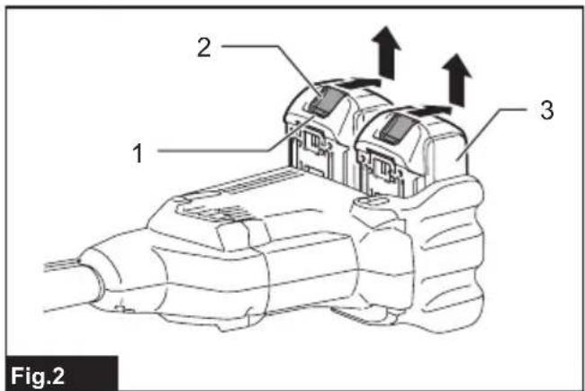
Installing or removing battery cartridge

CAUTION: Always switch off the tool before talling or removing of the battery cartridge.

CAUTION: Hold the tool and the battery car- lge firmly when installing or removing battery tridge. Failure to hold the tool and the battery tridge firmly may cause them to slip off your hands d result in damage to the tool and battery cartridge d a personal injury.
To install the battery cartridge, align the tongue on the battery cartridge with the groove in the housing and slip
it into place. Insert it all the way until it locks in place with a little click. If you can see the red indicator as shown in the figure, it is not locked completely.
To remove the battery cartridge, slide it from the tool while sliding the button on the front of the cartridge.
▶ Fig.2: 1. Red indicator 2. Button 3. Battery cartridge
⚠️CAUTION: Always install the battery cartridge fully until the red indicator cannot be seen. If not, it may accidentally fall out of the tool, causing injury to you or someone around you.
⚠️CAUTION: Do not install the battery cartridge forcibly. If the cartridge does not slide in easily, it is not being inserted correctly.
Tool / battery protection system
The tool is equipped with a tool/battery protection system. This system automatically cuts off power to the motor to extend tool and battery life. The tool will automatically stop during operation if the tool or battery is placed under one of the following conditions:
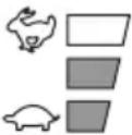
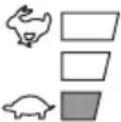
| Status Indicator lamps | |||
| On Off | Blinking | ||
| Overload |  | ||
| Overheat |  | ||
| Over discharge |  | ||
Overload protection
If the tool is overloaded by entangled weeds or other debris, and the middle indicators start blinking and the tool automatically stops.
In this situation, turn the tool off and stop the application that caused the tool to become overloaded. Then turn the tool on to restart.
Overheat protection for tool or battery
When a over heating occurs, all speed indicators blink. If the overheating occurs, the tool stops automatically. Let the tool and/or battery cool down before turning the tool on again.
Overdischarge protection
When the battery capacity becomes low, the tool stops automatically and 📋 Indicator blinks.
If the tool does not operate even when the switches are operated, remove the batteries from the tool and charge the batteries.
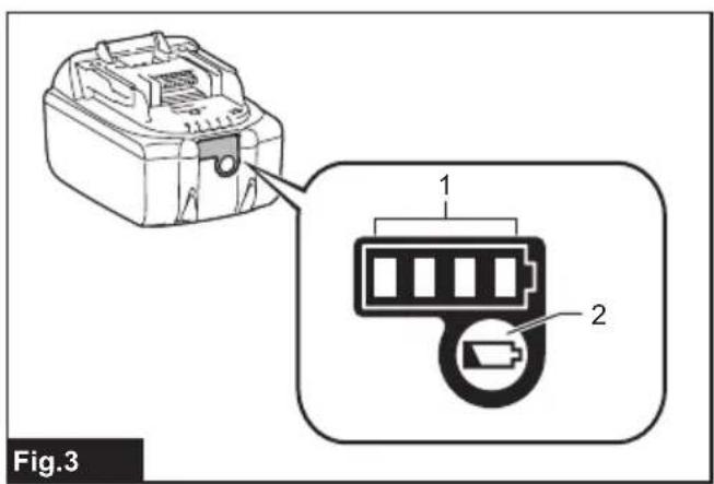
Indicating the remaining battery capacity
Only for battery cartridges with the indicator
Press the check button on the battery cartridge to indicate the remaining battery capacity. The indicator lamps light up for a few seconds.
▶ Fig.3: 1. Indicator lamps 2. Check button
| Indicator lamps Remaining | capacity | ||
| Lighted Of |  | ||
 | 75% to 100% | ||
 | 50% to 75% | ||
 | 25% to 50% | ||
 | 0% to 25% | ||
 | Charge the battery. | ||
 | The battery may have malfunctioned. | ||
 | |||
NOTE: Depending on the conditions of use and the ambient temperature, the indication may differ slightly from the actual capacity.
NOTE: The first (far left) indicator lamp will blink when the battery protection system works.
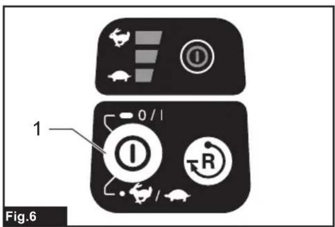
Main power switch
⚠ WARNING: Always turn off the main power switch when not in use.
To stand by the tool, press the main power button until the main power lamp lights up. To turn off, press the main power button again.
▶ Fig.4: 1. Main power button
NOTE: The main power lamp brinks if the switch trigger is pulled under unoperatable conditions. The lamp blinks if you turn on the main power switch while holding down the lock-off lever and the switch trigger.
NOTE: This tool employs the auto power-off function. To avoid unintentional start up, the main power switch will automatically shut down when the switch trigger is not pulled for a certain period after the main power switch is turned on.
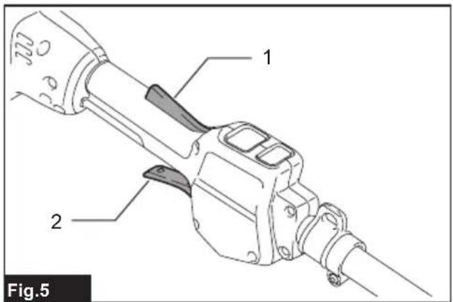
Switch action
WARNING: For your safety, this tool is equipped with lock-off lever which prevents the tool from unintended starting. NEVER use the tool if it runs when you simply pull the switch trigger without pressing the lock-off lever. Return the tool to our authorized service center for proper repairs BEFORE further usage.
WARNING: NEVER tape down or defeat purpose and function of lock-off lever.
⚠️CAUTION: Before installing the battery cartridge into the tool, always check to see that the switch trigger actuates properly and returns to the "OFF" position when released.
NOTICE: Do not pull the switch trigger hard without pressing the lock-off lever. This can cause switch breakage.
To prevent the switch trigger from being accidentally pulled, a lock-off lever is provided.
▶ Fig.5: 1. Lock-off lever 2. Switch trigger
To start the tool, turn on the main power switch and grasp the handle (the lock-off lever is released by the grasp) and then pull the switch trigger. Tool speed is increased by increasing the pressure on the switch trigger. To stop the tool, release the switch trigger.
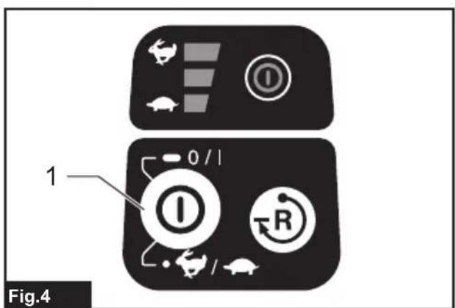
Speed adjusting
You can adjust the tool speed by tapping the main power button.
Each time you tap the main power button, the level of speed will change.
▶ Fig.6: 1. Main power button
| Indicator Mode | |
 | High |
 | Medium |
 | Low |
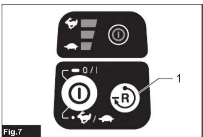
Reverse button for debris removal
WARNING: Switch off the tool and remove the battery cartridge before you remove entangled weeds or debris which the reverse rotation function can not remove. Failure to switch off and remove the battery cartridge may result in serious personal injury from accidental start-up.
This tool has a reverse button to change the direction of
rotation. It is only for removing weeds and debris entangled in the tool.
To reverse the rotation, tap the reverse button and pull the trigger when the tool's head is stopped. The power lamp starts blinking, and the tool's head rotates in reverse direction when you pull the switch trigger.
To return to regular rotation, release the trigger and wait until the tool's head stops.
▶ Fig.7: 1. Reverse button
NOTE: During the reverse rotation, the tool operates only for a short period of time and then automatically stops.
NOTE: Once the tool is stopped, the rotation returns to regular direction when you start the tool again.
NOTE: If you tap the reverse button while the tool's head is still rotating, the tool comes to stop and to be ready for reverse rotation.
Electronic torque control function
The tool electronically detects a sudden drop in the rotation speed which may cause a kickback. In this situation, the tool automatically stops to prevent further rotation of cutting tool. To restart the tool, release the switch trigger. Clear the cause of sudden drop in the rotation speed and then turn the tool on.
NOTE: This function is not a preventive measure for kickbacks.
ASSEMBLY
WARNING: Always be sure that the tool is switched off and battery cartridge is removed before carrying out any work on the tool. Failure to switch off and remove the battery cartridge may result in serious personal injury from accidental start-up.
WARNING: Never start the tool unless it is completely assembled. Operation of the tool in a partially assembled state may result in serious personal injury from accidental start-up.
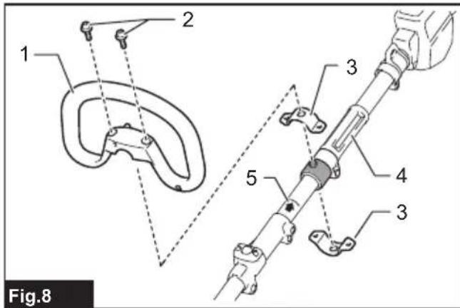
Mounting the handle
Attach the handle with supplied clamps and bolts. Make sure that the handle is located between the spacer and the arrow mark. Do not remove or shrink the spacer.
▶ Fig.8: 1. Handle 2. Hex socket bolt 3. Clamp 4. Spacer 5. Arrow mark
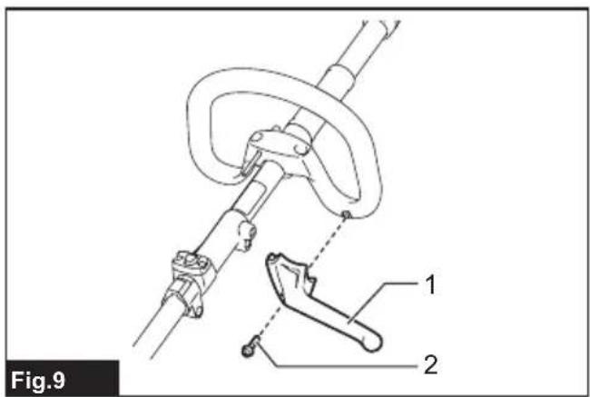
Attach the barrier (country specific) to the handle using the screw on the barrier. Once assembled, do not remove the barrier.
▶ Fig.9: 1. Barrier 2. Screw
Mounting the attachment pipe
CAUTION: Always check that the attachment pipe is secured after installation. Improper installation may cause the attachment falling off from the power unit and cause personal injury.
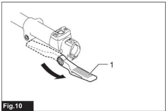
Mount the attachment pipe to the power unit.
- Turn the lever of the power unit toward the attachment side.
▶ Fig.10: 1. Lever
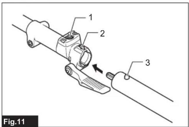
- Remove the cap of the attachment. Align the pin with the arrow mark and insert the attachment pipe until the release button pops up.
▶ Fig.11: 1. Release button 2. Arrow mark 3. Pin
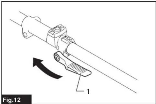
- Turn the lever toward the power unit side.
▶ Fig.12: 1. Lever
Make sure that the surface of the lever is parallel to the pipe.
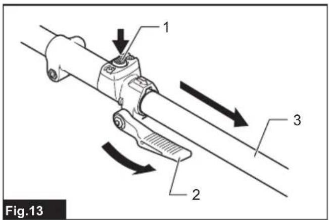
To remove the pipe, turn the lever toward the attachment side and pull the pipe out while pressing down the release button.
▶ Fig.13: 1. Release button 2. Lever 3. Pipe
Adjusting the handle/hanger position
Adjust the handle and hanger position to obtain comfortable handling of the tool.
Loosen the hex socket head bolt on the handle. Move the handle to a comfortable working position and then tighten the bolt.
▶ Fig.14: 1. Handle 2. Hex socket head bolt
Loosen the hex socket head bolt on the hanger. Move the hanger to a comfortable working position and then tighten the bolt.
▶ Fig.15: 1. Hex socket head bolt 2. Hanger
Attaching shoulder harness
WARNING: Be extremely careful to maintain control of the tool at all times. Do not allow the tool to be deflected toward you or anyone in the work vicinity. Failure to keep control of the tool could result in serious injury to the bystander and the operator.
⚠️CAUTION: Always use the shoulder harness attached. Before operation, adjust the shoulder harness according to the user size to prevent fatigue.
⚠CAUTION: When you use the tool in combination of the backpack-type power supply such as portable power pack, do not use the shoulder harness included in the tool package, but use the hanging band recommended by Makita.
If you put on the shoulder harness included in the tool package and the shoulder harness of the backpack-type power supply at the same time, removing the tool or backpack-type power supply is difficult in case of an emergency, and it may cause an accident or injury. For the recommended hanging band, ask Makita Authorized Service Centers.
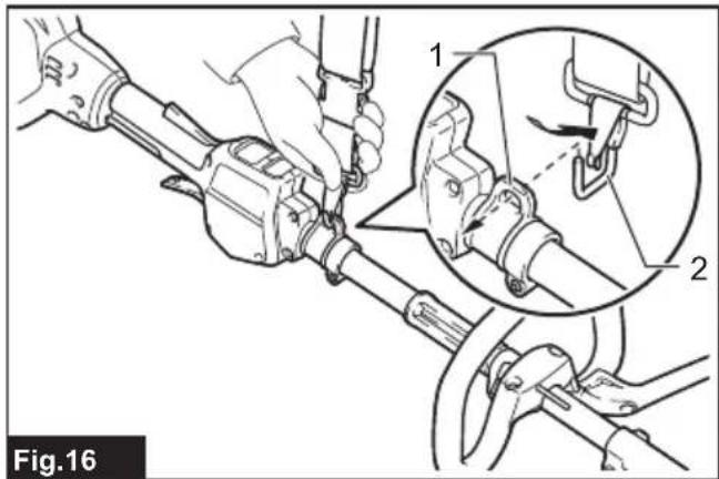
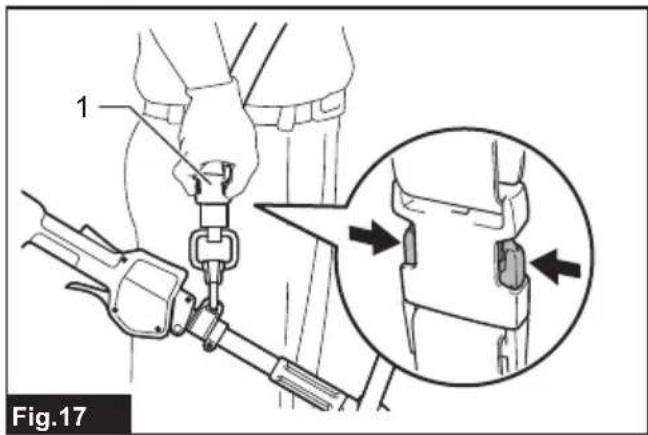
Put the shoulder harness on your left shoulder by putting your head and right arm through it. Keep the tool on your right side.
After putting the shoulder harness, attach it to the tool
by connecting the buckles provided on both the tool hook and the harness. Be sure that the buckles click and lock completely in place.
Adjust the strap to the suitable length for your operation.
▶ Fig.16: 1. Hanger 2. Hook
The buckle is provided with a means of quick release which can be accomplished by simply squeezing the sides and the buckle.
▶ Fig.17: 1. Buckle
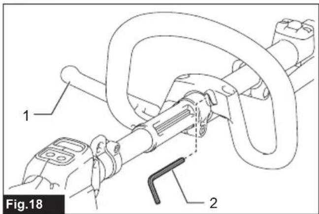
Hex wrench storage
CAUTION: Be careful not to leave the hex wrench inserted in the tool head. It may cause injury and/or damage to the tool.
When not in use, store the hex wrench as illustrated to keep it from being lost.
▶ Fig.18: 1. Handle 2. Hex wrench
MAINTENANCE
WARNING: Always be sure that the tool is switched off and battery cartridge is removed before attempting to perform inspection or maintenance on the tool. Failure to switch off and remove the battery cartridge may result in serious personal injury from accidental start-up.
NOTICE: Never use gasoline, benzine, thinner, alcohol or the like. Discoloration, deformation or cracks may result.
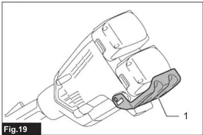
Battery guard
WARNING: Do not remove the battery guard. Do not use the tool with the battery guard removed or damaged. Direct impact to the battery cartridge may cause battery malfunction and result in injury and/or fire. If the battery guard is deformed or damaged, contact your authorized service center for repairs.
▶ Fig.19: 1. Battery guard
To maintain product SAFETY and RELIABILITY, repairs, any other maintenance or adjustment should be performed by Makita Authorized or Factory Service Centers, always using Makita replacement parts.
TROUBLESHOOTING
Before asking for repairs, conduct your own inspection first. If you find a problem that is not explained in the manual, do not attempt to dismantle the tool. Instead, ask Makita Authorized Service Centers, always using Makita replacement parts for repairs.
| State of abnormality Probable cause | (malfunction) Remedy | |
| Motor does not run. Battery cartridge is | not installed. Install the battery cartridge. | |
| Battery problem (under voltage) Recharge the battery. If recharging is not effective, replace battery. | ||
| The drive system does not work correctly. | Ask your local authorized service center for repair. | |
| Motor stops running after a little use. R | rotation is in reverse. Change the direction of rotation with the reversing switch. | |
| Battery's charge level is low. Recharge the battery. If recharging is not effective, replace battery. | ||
| Overheating. Stop using of tool to allow it to cool down. | ||
| It does not reach maximum RPM. B | battery is installed improperly. Install the battery cartridge as described in this manual. | |
| Battery power is dropping. Recharge the battery. If recharging is not effective, replace battery. | ||
| The drive system does not work correctly. | Ask your local authorized service center for repair. |
OPTIONAL ACCESSORIES
⚠️CAUTION: These accessories or attachments are recommended for use with your Makita tool specified in this manual. The use of any other accessories or attachments might present a risk of injury to persons. Only use accessory or attachment for its stated purpose.
If you need any assistance for more details regarding these accessories, ask your local Makita Service Center.
Refer to "Approved attachment" section for the applicable models for this tool.
- Edger attachment
- Brushcutter attachment
- String trimmer attachment
• Rotary scissors attachment - Grass trimmer attachment
• Hedge trimmer attachment
• Ground trimmer attachment - Pole saw attachment
• Coffee harvester attachment
• Cultivator attachment - Shaft extension attachment
• Power brush attachment
• Power sweep attachment - Blower attachment
- Pump attachment
- Weeding attachment
• Snow blower attachment
• Makita genuine battery and charger
NOTE: Some items in the list may be included in the tool package as standard accessories. They may differ from country to country.
SPÉCIFICATIONS
▶ Abb.17: 1. Schnalle
▶ Abb.18: 1. Handgriff 2. Inbusschlüssel
WARTUNG
VEILIGHEIDSWAAR- SCHUWINGEN
▶ Fig.7: 1. Omkeerknop
OPTIONELE ACCESSOIRES
▶ Fig.18: 1. Mango 2. Llave hexagonal
MANTENIMIENTO
▶ Fig.18: 1. Pega 2. Chave hexagonal