PT354DZ - Electric stapler MAKITA - Free user manual and instructions
Find the device manual for free PT354DZ MAKITA in PDF.

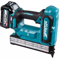
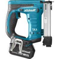
| Product Type | Cordless Electric Nailer |
| Brand | Makita |
| Model | PT354DZ |
| Rated Voltage | 10.8 V - 12 V DC max. |
| Battery Type | Lithium-ion (compatible BL1016, BL1021B, BL1041B, BL1050B) |
| Magazine Capacity | 100 headless nails |
| Nail Size | ø0.6 mm x 15, 18, 25, 30, 35 mm |
| Dimensions (L x W x H) | 231 mm x 80 mm x 226 mm (without hook) |
| Net Weight | 1.8 - 2.0 kg (depending on battery) |
| Sound Pressure Level | 76 dB(A) (uncertainty 3 dB) |
| Vibration Level | 2.5 m/s² or less (uncertainty 1.5 m/s²) |
| Battery Protection | Built-in protection system (overload, overdischarge, temperature) |
| LED Light | Yes, timed illumination (10 s) |
| Depth Adjustment | Knurled, up to 1.5 mm variation |
| Anti-Dry Fire Mechanism | Yes, activates with 0-3 nails remaining |
| Suspension Hook | Removable, side attachment |
| Nose Adapter | Included, for fragile surfaces |
| Maintenance | Exterior cleaning with dry cloth; no solvents |
| Repairability | Original Makita spare parts, repair at authorized center |
Frequently Asked Questions - PT354DZ MAKITA
User questions about PT354DZ MAKITA
0 question about this device. Answer the ones you know or ask your own.
Ask a new question about this device
Download the instructions for your Electric stapler in PDF format for free! Find your manual PT354DZ - MAKITA and take your electronic device back in hand. On this page are published all the documents necessary for the use of your device. PT354DZ by MAKITA.
USER MANUAL PT354DZ MAKITA
| Model: PT354D | |
| Pin nail size ø0.6 mm x 15, 18, 25, 30, 35 mm | |
| Pin nail magazine capacity 100 pcs. | |
| Dimensions without hook (L x W x H) 231 mm x 80 mm x 226 mm | |
| Rated voltage D.C. 10.8 V - 12 V max | |
| Net weight 1.8 - 2.0 kg |
- Due to our continuing program of research and development, the specifications herein are subject to change without notice.
- Specifications and battery cartridge may differ from country to country.
The weight may differ depending on the attachment(s), including the battery cartridge. The lightest and heaviest combinations, according to EPTA-Procedure 01/2014, are shown in the table.
Applicable battery cartridge and charger
Battery cartridge BL1016 / BL1021B / BL1041B / BL1050B
Charger DC10SA / DC10SB / DC10WC / DC10WD / DC18RE
- Some of the battery cartridges and chargers listed above may not be available depending on your region of residence.

WARNING: Only use the battery cartridges and chargers listed above. Use of any other battery cartridges and chargers may cause injury and/or fire.
Intended use
The tool is intended for pressing pin nails into construction materials such as timbers.
Noise
The typical A-weighted noise level determined according to EN60745:
Sound pressure level (L_pA):76 dB (A)
Uncertainty (K): 3 dB (A)
The noise level under working may exceed 80 dB (A).

WARNING: Wear ear protection.
Vibration
The vibration total value determined according to EN60745:
Vibration emission (a_h):2.5m / s^2 or less
Uncertainty (K): 1.5m / s^2
NOTE: The declared vibration total value(s) has been measured in accordance with a standard test method and may be used for comparing one tool with another.
NOTE: The declared vibration total value(s) may also be used in a preliminary assessment of exposure.

WARNING: The vibration emission during actual use of the power tool can differ from the declared value(s) depending on the ways in which the tool is used especially what kind of workpiece is processed.

WARNING: Be sure to identify safety measures to protect the operator that are based on an estimation of exposure in the actual conditions of the site (taking account of all parts of the operating cycle such as the times when the tool is switched off and when it is running idle in addition to the trigger time).
Declarations of Conformity
For European countries only
The Declarations of conformity are included in Annex A to this instruction manual.
SAFETYWARNINGS
General power tool safety warnings
WARNING Read all safety warnings, instructions, illustrations and specifications provided with this power tool. Failure to follow all instructions listed below may result in electric shock, fire and/or serious injury.
Save all warnings and
instructions for future reference.
The term "power tool" in the warnings refers to your mains-operated (corded) power tool or battery-operated (cordless) power tool.
Cordless nailer safety warnings
- Always assume that the tool contains fasteners. Careless handling of the nailer can result in unexpected firing of fasteners and personal injury.
- Do not point the tool towards yourself or any- one nearby. Unexpected triggering will discharge the fastener causing an injury.
- Do not actuate the tool unless the tool is placed firmly against the workpiece. If the tool is not in contact with the workpiece, the fastener may be deflected away from your target.
- Disconnect the tool from the power source when the fastener jams in the tool. While removing a jammed fastener, the nailer may be accidentally activated if it is plugged in.
- Use caution while removing a jammed fastener. The mechanism may be under compression and the fastener may be forcefully discharged while attempting to free a jammed condition.
- Do not use this nailer for fastening electrical cables. It is not designed for electric cable installation and may damage the insulation of electric cables thereby causing electric shock or fire hazards.
- Always wear safety glasses to protect your eyes from dust or fastener injury.
WARNING: It is an employer's responsibility to enforce the use of safety eye protection equipment by the tool operators and by other persons in the immediate working area. - Keep hands and feet away from the ejection port area.
- Follow instruction for lubricating and changing accessories.
- Always remove the battery cartridge before loading the fasteners, adjustment, inspection, maintenance or after operation is over.
- Make sure no one is nearby before operation. Never attempt to drive fasteners from both the inside and outside of wall at the same time. Fasteners may rip through and/or fly off, presenting a grave danger.
- Watch your footing and maintain your balance with the tool. Make sure there is no one below when working in high locations.
-
Never use fastener driving tools marked with the symbol "Do not use on scaffoldings, ladders" for specific application for example:
-
when changing one driving location to another involves the use of scaffoldings, stairs, ladders, or ladder alike constructions, e.g. roof laths;
closing boxes or crates; -
fitting transportation safety systems e.g. on vehicles and wagons.
-
Check walls, ceilings, floors, roofing and the like carefully to avoid possible electrical shock, gas leakage, explosions, etc. caused by
stapling into live wires, conduits or gas pipes.
- Use only fasteners specified in this manual. The use of any other fasteners may cause malfunction of the tool.
- Do not tamper with the tool or attempt to use it for other than driving fasteners.
- Do not operate the tool without fasteners. It shortens the service life of the tool.
- Stop driving operations immediately if you notice something wrong or out of the ordinary with the tool.
- Never fasten into any materials which may allow the fastener to puncture and fly through as a projectile.
- Never actuate the switch trigger and contact element at the same time until you are prepared to fasten workpieces. Allow the workpiece to depress the contact element. Never defeat its purpose by securing the contact element back or by depressing it by hand.
- Never tamper with the contact element. Check the contact element frequently for proper operations.
- Always remove fasteners from the tool when not in use.
SAVE THESE INSTRUCTIONS.
WARNING: DO NOT let comfort or familiarity with product (gained from repeated use) replace strict adherence to safety rules for the subject product. MISUSE or failure to follow the safety rules stated in this instruction manual may cause serious personal injury.
Important safety instructions for battery cartridge
- Before using battery cartridge, read all instructions and cautionary markings on (1) battery charger, (2) battery, and (3) product using battery.
- Do not disassemble or tamper with the battery cartridge. It may result in a fire, excessive heat, or explosion.
- If operating time has become excessively shorter, stop operating immediately. It may result in a risk of overheating, possible burns and even an explosion.
-
If electrolyte gets into your eyes, rinse them out with clear water and seek medical attention right away. It may result in loss of your eyesight.
-
Do not short the battery cartridge:
(1) Do not touch the terminals with any conductive material.
(2) Avoid storing battery cartridge in a container with other metal objects such as nails, coins, etc.
(3) Do not expose battery cartridge to water or rain.
A battery short can cause a large current flow, overheating, possible burns and even a breakdown.
- Do not store and use the tool and battery cartridge in locations where the temperature may reach or exceed 50^ (122°F).
- Do not incinerate the battery cartridge even if it is severely damaged or is completely worn out. The battery cartridge can explode in a fire.
- Do not nail, cut, crush, throw, drop the battery cartridge, or hit against a hard object to the battery cartridge. Such conduct may result in a fire, excessive heat, or explosion.
- Do not use a damaged battery.
- The contained lithium-ion batteries are subject to the Dangerous Goods Legislation requirements.
For commercial transports e.g. by third parties, forwarding agents, special requirement on packaging and labeling must be observed.
For preparation of the item being shipped, consulting an expert for hazardous material is required. Please also observe possibly more detailed national regulations.
Tape or mask off open contacts and pack up the battery in such a manner that it cannot move around in the packaging.
- When disposing the battery cartridge, remove it from the tool and dispose of it in a safe place. Follow your local regulations relating to disposal of battery.
- Use the batteries only with the products specified by Makita. Installing the batteries to non-compliant products may result in a fire, excessive heat, explosion, or leak of electrolyte.
- If the tool is not used for a long period of time, the battery must be removed from the tool.
- During and after use, the battery cartridge may take on heat which can cause burns or low temperature burns. Pay attention to the handling of hot battery cartridges.
- Do not touch the terminal of the tool immediately after use as it may get hot enough to cause burns.
- Do not allow chips, dust, or soil stuck into the terminals, holes, and grooves of the battery cartridge. It may cause heating, catching fire, burst and malfunction of the tool or battery cartridge, resulting in burns or personal injury.
- Unless the tool supports the use near high-voltage electrical power lines, do not use the battery cartridge near high-voltage electrical power lines. It may result in a malfunction or breakdown of the tool or battery cartridge.
- Keep the battery away from children.
SAVE THESE INSTRUCTIONS.
CAUTION: Only use genuine Makita batteries. Use of non-genuine Makita batteries, or batteries that have been altered, may result in the battery bursting causing fires, personal injury and damage. It will also void the Makita warranty for the Makita tool and charger.
Tips for maintaining maximum battery life
- Charge the battery cartridge before completely
discharged. Always stop tool operation and charge the battery cartridge when you notice less tool power.
- Never recharge a fully charged battery cartridge. Overcharging shortens the battery service life.
- Charge the battery cartridge with room temperature at 10^ - 40^ (50°F - 104°F). Let a hot battery cartridge cool down before charging it.
- When not using the battery cartridge, remove it from the tool or the charger.
FUNCTIONAL DESCRIPTION
CAUTION: Always be sure that the tool is switched off and the battery cartridge is removed before adjusting or checking function on the tool.
Installing or removing battery cartridge
CAUTION: Always switch off the tool before installing or removing of the battery cartridge.
CAUTION: Hold the tool and the battery cartridge firmly when installing or removing battery cartridge. Failure to hold the tool and the battery cartridge firmly may cause them to slip off your hands and result in damage to the tool and battery cartridge and a personal injury.
To install the battery cartridge, align the tongue on the battery cartridge with the groove in the housing and slip it into place. Insert it all the way until it locks in place with a little click. If you can see the red indicator as shown in the figure, it is not locked completely.
To remove the battery cartridge, slide it from the tool while sliding the button on the front of the cartridge.
Fig.1: 1. Red indicator 2. Button 3. Battery cartridge
CAUTION: Always install the battery cartridge fully until the red indicator cannot be seen. If not, it may accidentally fall out of the tool, causing injury to you or someone around you.
CAUTION: Do not install the battery cartridge forcibly. If the cartridge does not slide in easily, it is not being inserted correctly.
Battery protection system
The tool is equipped with a battery protection system.
This system automatically cuts off power to the motor to extend battery life.
The tool will automatically stop during operation if the tool and/or battery are placed under one of the following conditions:
Overloaded:
The tool is operated in a manner that causes it to draw an abnormally high current.
In this situation, turn the tool off and stop the application that caused the tool to become overloaded. Then turn the tool on to restart.
If the tool does not start, the battery is overheated. In this situation, let the battery cool before turning the tool on again.
Low battery voltage:
The remaining battery capacity is too low and the tool will not operate. If you turn the tool on, the motor does not run or the motor runs again but stops soon. In this situation, remove and recharge the battery.
Indicating the remaining battery capacity
Only for battery cartridges with the indicator
Fig.2: 1. Indicator lamps 2. Check button
Press the check button on the battery cartridge to indicate the remaining battery capacity. The indicator lamps light up for a few seconds.
| Indicator lamps Remaining | capacity | |
| Lighted Off | □ | |
| 75% to 100% | ||
| 50% to 75% | ||
| 25% to 50% | ||
| 0% to 25% | ||
NOTE: Depending on the conditions of use and the ambient temperature, the indication may differ slightly from the actual capacity.
Trigger-lock button
CAUTION: Before installing the battery cartridge into the tool, always check to see that the switch trigger actuates properly and returns to the "OFF" position when released.
CAUTION: When not operating the tool, depress the trigger-lock button from B side to lock the switch trigger in the OFF position.
Fig.3: 1. Trigger-lock button 2. Switch trigger
Fig.4
To prevent the switch trigger from accidentally pulled, the trigger-lock button is provided.
To pull the switch trigger, depress the trigger-lock button from A side.
After use, always press in the trigger-lock button from B side.
Adjusting the depth of pin-nailing
WARNING: Always make sure that your fingers are not placed on the switch trigger or the contact element and the battery cartridge is removed before adjusting the depth of nailing.
Depth of pin-nailing can be adjusted on this pin nailer. To adjust the depth of nailing, turn the adjuster. The depth of nailing is the deepest when the adjuster is turned fully in the A direction shown in the figure. It will become shallower as the adjuster is turned in the B direction. Depth can be adjusted 1.5mm to the maximum.
Fig.5: 1. Adjuster
Fig.6: 1. Too deep 2. Flush 3. Too shallow
Lighting up the lamp
CAUTION: Do not look in the light or see the source of light directly.
Pull the switch trigger or actuate the contact element to light up the lamp. The lamp keeps on lighting while pulling the switch trigger or actuating the contact element. The lamp goes out approximately 10 seconds after releasing the switch trigger and the contact element.
Fig.7: 1. Lamp
NOTE: Use a dry cloth to wipe the dirt off the lens of the lamp. Be careful not to scratch the lens of the lamp, or it may lower the illumination.
NOTE: Even in the lamp lights up when the battery power residual gets small, pin nailer may not fire pin nails. In this case, charge the battery cartridge.
ASSEMBLY
CAUTION: Always make sure that your fingers are not placed on the switch trigger or the contact element and the battery cartridge is removed before carrying out any work on the pin nailer.
Loading the pin nailer
CAUTION: Always make sure that the battery cartridge is removed before loading the pin nailer. Unintentional firing may cause personal injuries and property damage.
CAUTION: Do not abruptly slide the magazine of the pin nailer loaded with pin nails. Accidentally dropping pin nails especially when working in high places may cause personal injuries.
CAUTION: Load pin nails in the correct direction. Loading in wrong direction may cause premature wear and tear of the driver and damage of the other parts.
CAUTION: Do not use deformed connected pin nails. Use pin nails specified in this manual. Using pin nails other than those specified may cause pin nail jamming and breakage of the pin nailer.
- Remove the battery cartridge.
- Press the locking lever and slide the magazine backward.
- Align the tip of pin nails with the grooves at the
bottom of the magazine and push the whole part of pin nails toward the driver guide. (Be careful to place pin nails in the right direction.)
▶ Fig.8: 1. Pin nails 2. Magazine 3. Locking lever 4. Driver guide
- After loading pin nails, push back the magazine in place until it clicks.
To remove pin nails, follow the installation procedures in reverse.
Nose adapter
CAUTION: Always make sure that your fingers are not placed on the switch trigger or the contact element and the battery cartridge is removed before installing the nose adapter.
When firing pin nails on the material with easily-marred surfaces, use the nose adapter. To install the nose adapter, place it over the driver guide cover so that the protrusion inside the nose adapter fits to the dent in the driver guide cover.
You can store the nose adapter on the holder on the back end of the magazine to keep it from being lost.
▶ Fig.9: 1. Dent 2. Protrusion 3. Nose adapter 4. Holder
Hook
CAUTION: Do not hang the hook from the waist belt. Dropping the pin nailer, which is caused by the hook accidentally coming out of place, may cause unintentional firing and result in personal injuries.
Fig.10
WARNING: Use the hanging/mounting parts for their intended purposes only, e.g., hanging the tool on a tool belt between jobs or work intervals.
WARNING: Be careful not to overload the hook as too much force or irregular overburden may cause damages to the tool resulting in personal injury.
CAUTION: When installing the hook, always secure it with the screw firmly. If not, the hook may come off from the tool and result in the personal injury.
CAUTION: Make sure to hang the tool securely before releasing your hold. Insufficient or unbalanced hooking may cause falling off and you may be injured.
NOTE: When using the tool with battery BL1050B, the optional hook dedicated for BL1050B is needed.
The hook is convenient for temporarily hanging the tool. This can be installed on either side of the tool. To install the hook, insert it into a groove in the tool housing on either side and then secure it with a screw. To remove, loosen the screw and then take it out.
Fig.11: 1. Groove 2. Hook 3. Screw
Hex wrench storage
When not in use, store the hex wrench as shown in the figure to keep it from being lost.
Fig.12: 1. Hex wrench
OPERATION
Testing the safety system
WARNING: Make sure all safety systems are in working order before operation. Failure to do so may cause personal injuries.
▶ Fig.13: 1. Trigger-lock button 2. Switch trigger 3. Contact element 4. Magazine
Test safety systems for possible fault before operation as follows.
- Unload pin nails from the tool and keep the magazine opened.
- Install the battery cartridge and release the trigger lock.
- Only pull the switch trigger without touching the contact element against the material.
- Only touch the contact element against the material without pulling the switch trigger.
If the tool operates in the case of 3 and 4 above, the safety systems are faulty. Stop using the tool immediately and ask your local service center.
Driving pin nails
WARNING: Continue to place the contact element firmly on the material until the pin nail is driven completely. Unintentional firing may cause personal injuries.
- Release the trigger lock.
- Place flat the contact element on the material.
- Pull the switch trigger fully to drive a pin nail.
- To drive the next pin nail, release your finger from the switch trigger once, and then repeat the step 2 and 3 above.
Fig.14: 1. Switch trigger 2. Contact element
You can also drive the pin nails when dragging the tool to the next area with the contact element pressed against the material and pulling the switch trigger.
Fig.15
If the head of the pin nail remains above the workpiece surface, drive the pin nail while holding the pin nailer head firmly against the workpiece.
Fig.16
NOTE: If the head of the pin nail still remains above the workpiece even you hold the pin nail head, the material may not be suitable for the pin nailer. Continuing to use the pin nailer on such material may result in a damage to the driver of the pin nailer and/or pin nailer jamming.
Anti dry fire mechanism
WARNING: Always make sure that your fingers are not placed on the switch trigger or the contact element and the battery cartridge is removed before loading the pin nailer.
When the number of remaining pin nails in the magazine are 0 - 3 pieces, the switch trigger can no longer be pulled. At this time, insert a new strip of pin nails in the magazine and the switch trigger can be pulled again.
NOTE: When firing a different length of pin nails shortly after the anti-dry firing device has actuated, insert a new strip of pin nails into the magazine and fire away all the prior pin nails that have remained on junk material.
Checking remaining pin nails
You can check the amount of remaining pin nails through the sight window.
The red indicator moves toward fastening opening with the amount of remaining pin nails become smaller.
Fig.17: 1. Sight window 2. Indicator
Removing jammed pin nails
WARNING: Always make sure that the battery cartridge is removed before removing jammed pin nails.
Take out pin nails that remain inside the magazine. Remove three screws with the hex wrench that are securing the driver guide cover.
Take the jammed nails from the nail guide groove that has appeared.
When it is difficult to take out the jammed nails, further remove two screws with the hex wrench that are securing the contact top cover. Then take them out.
Fig.18: 1. Driver guide cover 2. Screw 3. Contact top cover
MAINTENANCE
CAUTION: Always be sure that the tool is switched off and the battery cartridge is removed before attempting to perform inspection or maintenance.
NOTICE: Never use gasoline, benzine, thinner, alcohol or the like. Discoloration, deformation or cracks may result.
To maintain product SAFETY and RELIABILITY, repairs, any other maintenance or adjustment should
be performed by Makita Authorized or Factory Service Centers, always using Makita replacement parts.
OPTIONAL ACCESSORIES
CAUTION: These accessories or attachments are recommended for use with your Makita tool specified in this manual. The use of any other accessories or attachments might present a risk of injury to persons. Only use accessory or attachment for its stated purpose.
If you need any assistance for more details regarding these accessories, ask your local Makita Service Center.
Pin nails
- Hook
- Makita genuine battery and charger
NOTE: Some items in the list may be included in the tool package as standard accessories. They may differ from country to country.
SPECIFICATIONS
ACCESSIONS EN OPTION
VEILIGHEIDSWAAR-SCHUWINGEN
OPTIONELE ACCESSOIRES
Móvo yia xwpeS Tns Eupwnns
Oi Anwosicuupoppwong Tepiaaavovtai oTo Iapaptnma A oTo npov EYxepidio odnyiwv.
ПОНТОИЗEGI
AΣΦΑΛΕΙΑΣ
Evikc ppoedotoinoic aovaaiayia TO nEKTpiko epyaeeio
A PPOEI OIOIH H IaIaOte oIe TIC TPOEI- 0oioinoeic aopaleiac, odnyie, EIKOVoypapnoeic KAI TPOBIAYPAPcE TOU TApexovTai e auto To nKTPiKO epyAAEO. H mtnpnon oawv twv onyiWv Tou avayapovTai katwtpew mTOpEi va kataanxi OE nKTOPTAnxi, TUPKAYIA n/kai oBapo tpaumatioo.
ΦuαTe oεc TIG PPOEIOIOn-σεic kai TIG OByeC yia μελIoVTIKn TApapouπn.
TIC TPOEIDOTIOINOEIS, O oPoC «NtEeTIPOEpyaIIOVAvaepetai OE nEeTIPOEpyaIIO TIOU TPOPOOTeiTAI aTO TIV KUPIA TAPoxn NtEeTIPOU PEUMATOS (ME NtEeKTIPOKOALWIO) n OE nEeTIPOEpyaIIO TIOU TPOPOOTeiTAI aTO UTApia (XwpiNtEeTIPOK KaWIO).
PpOeIbOToIOInoEic aOaAeiaC yia To 0opnto kapawtiko
- Na UTOθETETIa OTI TO Epyaleio TEPiExei OuvdTepec.O aTPOeKTOC XeipIOuO Tou KAp- QWTIKOU mTopei va KAATAHgEi OE u avapeVOpEvn TUPoδoTOn OuvdEtnpW KAI TpaUpatioo.
- Mny Otpepete To EpyaIeio TpoC To Mepos aC n TPOCS OTOIOBnTote aaLo aToMo Ekei KovTa.H avauevouevn TupodotnAn TpokaEkTivaEg Tou ouvOEtnpa TpokawVtac Tpaumatuo.
- Mv EvpyoTOIETo EpyaIeIO EKToc Eav ExTe TOnTOETNOEi To EpyaIeio OaOepa OE ENaPn ME TO TEuaxio EpyaOiaC.Eav To EpyaIeio Dv Exei TOnTOETnOei OtaOepa OE ENaPn ME TO TEuaxio EpyaOiaC, Ouvdtnpac MTOpEi va EKtpanEi aTTo OToxo Tou.
- ATOOuvdeTo Epyaleio aTo TnV Tnyntpofooboiac otav npouoiaotei eMLOkni Tou Ouvetnpa eoea oTo Epyaleio.OTAV EITIXeipeite va apaipeoTe evav mloakipaevo ouvdtnpa, TO KAPWtIKo MTopei va Evepyotointhe TuXia av eivai ouvdeEevo.
- Na eioTE TPOOeKIOI KATA TNV aapapeoN evoc (\mu \pi \lambda o k a p i \sigma \mu \varepsilon v o u \delta e t \pi p a) . O mnxaviouc (\mu \pi o p e i v a \beta p i o k e t a i u \pi o u p t i e o n k a i o u v dEtnpac va EKTIVAXe i biia otav ETIIXeipnoTe va (\varepsilon \lambda \varepsilon \upsilon \theta e p w o e t e \varepsilon v a \mu \pi \lambda o k a p i \sigma \mu e v o \varepsilon p y a \lambda e i o.)
- Mny xpnoiopoioite auto To KAPpwTko yia Tn OTEpeown nEeKtpikwv kaawbiv. evai oxediaouvo ia tvn totoettnan nEeKpikwv kaawdiwv kai tnpoei va tpokalaeoi aBn otn movon twv nEeKtpikwv kaawdiwv aTOTe- Aeoua va tpokanthe i nEeKtpoTTAnxi a n kivduvo tsupkayiac.
- Opate navote yuaia aopaaeiac yia va TPOoTATEUETa maia oac ato tn okovn n ato TpaumatoaTOUCouvdtpeC. A PPOEIAOIOIHs: O epyobotnc oepieia va EIIaaiI th xpnon mewv pooataiag ia
Ta maTia OTouc Xeipiotc Tou Epyaieiou Kai Oe aaaa atoMa otnv ameOn Tepioxn Epyaiaac.
- Na Kpatate Ta xepia Kai Ta Tóbia Oac Japkiα aTó TnV TEPIOXn Tns Θ Upac EKtivaξns.
- Na akoaloutheiTe Tc obnyie yia tn aiavon kai tv aalayn twv eapntmuatwv.
- Na yacete TnV Ta nV Kaaet a mTataipwv Tpiv Tnv TOnoTheon Ouvoetnpwv, Tn puOmuon, Tov EeYxo, Tn ouvtnpn o n eTo TEaoc Tns λeitoupyiaC.
- SIVOUPEUTE OI DEV Bpioketai Kaveic Kovta aac Tn aeitoupyia. Mny Tpootaa n-ote va kapwote ouvdtpe TaTOxPOVA aTTO NVEoWTEPIKn KAI TNY EeWTEPIKn PLEUPa TOU Toixou. OI ouvdtpec mtopei va dianepaoov tv TOIXO h/kai va pTeaTOUV biaia, PpOKawTAC TOLu oobapo kivduvo.
- Ipooexete To otpiyma Tuv Ndiow osk kai diatnpite TIV IOoppoia oac me TO epyaaleio. Beaiwtheta OTI DEV Unpxie Kaveic aTkoKATOW otav epyaceote OE uynlecs totoeeiec.
- Noté μη χροπιομοτοί έετε καρφωτικά πισόλία του φέρουν τήν εύδειξη «Mη χροπιομοτοίεITE σε σκαλωσιές, σκαλές, κτλ.» για εἰδικές εφαρμογές σπως για παράδειγμα:
otav kata tny aalayn atio ma tottoeia kapawmuoc oia aaan xnpoiotiouvtai okaawoe, okaotntia, okaee n aaaes TAPoouie c kataaekuec, T.x. avidec OKETIWV,
- kaTAtKλεσιμo Kβωτfωv n τελαρωv,
Kata TnV eapuoyn ouotnuw aopaleiae μetapopovπ.x. oXnua tka bayovia.