SHD 30 S - Boiler STIEBEL ELTRON - Free user manual and instructions
Find the device manual for free SHD 30 S STIEBEL ELTRON in PDF.
| Product Type | Electric Storage Water Heater |
| Brand | STIEBEL ELTRON |
| Model | SHD 30 S |
| Tank Capacity | 30 L |
| Dimensions (H x W x D) | 770 x 410 x 420 mm |
| Empty Weight | 24.3 kg |
| Full Weight | 54.3 kg |
| Electrical Supply | 3/PE ~ 400 V, 50 Hz |
| Connected Load | 3.5 / 21 kW (normal / rapid) |
| Temperature Setting Range | 35 °C to 85 °C |
| Maximum Permissible Pressure | 0.6 MPa (6 bar) |
| Maximum Flow Rate | 18 L/min |
| Protection Rating | IP25 |
| Energy Efficiency Class | B |
| Annual Electricity Consumption | 518 kWh |
| Load Profile | S |
| Operating Modes | Instantaneous tank, dual power, single power |
| Frost Protection | Yes (depending on mode) |
| Protection Anode | Yes, with SERVICE ANODE indicator |
| Cleaning | Damp cloth, no abrasive products |
| Safety | Safety limiter, safety valve, recommended RCD |
| Repairability | Interventions by qualified installer, spare parts available |
Frequently Asked Questions - SHD 30 S STIEBEL ELTRON
User questions about SHD 30 S STIEBEL ELTRON
0 question about this device. Answer the ones you know or ask your own.
Ask a new question about this device
Download the instructions for your Boiler in PDF format for free! Find your manual SHD 30 S - STIEBEL ELTRON and take your electronic device back in hand. On this page are published all the documents necessary for the use of your device. SHD 30 S by STIEBEL ELTRON.
USER MANUAL SHD 30 S STIEBEL ELTRON
BEDIENUNG UND INSTALLATION OPERATION AND INSTALLATION UTILISATION ET INSTALLATION BEDIENING EN INSTALLATIE OBSLUHA A INSTALACE ЭКСПЛУАТАЦИЯ И УСТАНОВКА OBSŁUGA I INSTALACJA OBSLUHA A INŠTALÁCIA
Geschlossener Warmwasser-Durchlaufspeicher | Sealed instantaneous DHW cylinder | Chauffe-eau instantané en circuit fermé | Gesloten warmwater-doorloopboiler | Tlakový průtokový zásobník teplé vody | Проточный водонагреватель закрытого типа | Ciśnieniowy zasobnik przepływowy ciepłej wody | Uzavretý prietokový zásobník teplej vody
natural_image
Front view of a rectangular appliance with a vertical seam and control knob (no text or symbols)STIEBEL ELTRON
BESONDERE HINWEISE
BEDIENUNG
natural_image
Technical line drawing of a structural support frame with mounting bracket and grid base (no text or symbols)natural_image
Technical line drawing of a mechanical assembly with mounting holes and a scale (no text or symbols)Temperatur-Einstellknopf
natural_image
Technical line drawing of a mechanical assembly with cross-sectional and top views (no text or symbols)1 EVU-Kontakt
- General information 17
1.1 Safety instructions 17
1.2 Other symbols in this documentation ____ 17
1.3 Units of measurement 17 - Safety 17
2.1 Intended use 17
2.2 General safety instructions 18
2.3 Test symbols 18 - Appliance description 18
- Settings 19
- Cleaning, care and maintenance 19
- Troubleshooting 19
INSTALLATION
- Safety 20
7.1 General safety instructions 20
7.2 Instructions, standards and regulations ____ 20 - Appliance description 20
8.1 Standard delivery 20
8.2 Accessories 20 - Preparations 20
9.1 Installation site 20
9.2 Fitting the wall mounting bracket 20
9.3 Preparing the power cable 20 - Installation 21
10.1 Water connection 21
10.2 Appliance installation 21
10.3 Power supply 21 - Commissioning 22
11.1 Initial start-up 22
11.2 Recommissioning 22 - Settings 22
- Shutdown 23
- Troubleshooting 23
- Maintenance 23
15.1 Checking the safety valve 23
15.2 Draining the appliance 23
15.3 Replacing the protective anode 24
15.4 Descaling 24
15.5 Anti-corrosion protection 24 - Specification 25
16.1 Dimensions and connections 25
16.2 Wiring diagrams and terminals 26
16.3 Output tables 27
16.4 Fault conditions 27
16.5 Details on energy consumption 27
16.6 Data table 27
GUARANTEE
ENVIRONMENT AND RECYCLING
SPECIAL INFORMATION
- The appliance may be used by children aged 8 and older and persons with reduced physical, sensory or mental capabilities or a lack of experience and know-how, provided that they are supervised or they have been instructed on how to use the appliance safely and have understood the resulting risks. Children must never play with the appliance. Children must never clean the appliance or perform user maintenance unless they are supervised.
- The connection to the power supply is only permissible as a permanent connection in conjunction with the removable cable grommet. Ensure the appliance can be separated from the power supply by an isolator that disconnects all poles with at least 3 mm contact separation.
- Fix the appliance in position as described in chapter "Installation / Preparations".
- Observe the maximum permissible pressure (see chapter "Installation / Specification / Data table").
- Drain the appliance as described in chapter "Installation / Maintenance / Draining the appliance".
- The appliance is pressurised. During the heat-up process, expansion water will drip from the safety valve.
- Regularly activate the safety valve to prevent it from becoming blocked, e.g. by limescale deposits.
- Install a type-tested safety valve in the cold water supply line. Please note that, depending on the static pressure, you may also need a pressure reducing valve.
- Size the drain pipe so that water can drain off unimpeded when the safety valve is fully opened.
- Fit the discharge pipe of the safety valve with a constant downward slope and in a room free from the risk of frost.
- The safety valve discharge aperture must remain open to atmosphere.
OPERATION
1. General information
The chapters "Special Information" and "Operation" are intended for both the user and qualified contractors.
The chapter "Installation" is intended for qualified contractors.

Note
Read these instructions carefully before using the appliance and retain them for future reference.
Pass on the instructions to a new user if required.
1.1 Safety instructions
1.1.1 Structure of safety instructions

KEYWORD Type of risk
Here, possible consequences are listed that may result from failure to observe the safety instructions.
▶ Steps to prevent the risk are listed.
1.1.2 Symbols, type of risk
Symbol Type of risk

Injury

Electrocution

Burns
(burns, scalding)
1.1.3 Keywords
KEYWORD Meaning
DANGER Failure to observe this information will result in serious injury or death.
WARNING Failure to observe this information may result in serious injury or death.
CAUTION Failure to observe this information may result in non-serious or minor injury.
1.2 Other symbols in this documentation

Note
General information is identified by the adjacent symbol.
▶ Read these texts carefully.
Symbol Meaning

Material losses
(appliance damage, consequential losses and environmental pollution)

Appliance disposal
This symbol indicates that you have to do something. The action you need to take is described step by step.
1.3 Units of measurement

Note
All measurements are given in mm unless stated otherwise.
2. Safety
2.1 Intended use
The appliance is intended for heating domestic hot water and can supply one or more draw-off points.
This appliance is intended for domestic use. It can be used safely by untrained persons. The appliance can also be used in a non-domestic environment, e.g. in a small business, as long as it is used in the same way.
Any other use beyond that described shall be deemed inappropriate. Using the appliance for heating fluids other than water or for water supplemented with chemicals, such as brine, is also deemed inappropriate.
Observation of these instructions and of instructions for any accessories used is also part of the correct use of this appliance.
2.2 General safety instructions

WARNING Burns
During operation, the tap/valve and safety assembly can reach temperatures in excess of 60 °C.
There is a risk of scalding at outlet temperatures in excess of 43^ C.

WARNING Injury
The appliance may be used by children aged 8 and older and persons with reduced physical, sensory or mental capabilities or a lack of experience and know-how, provided that they are supervised or they have been instructed on how to use the appliance safely and have understood the resulting risks. Children must never play with the appliance. Children must never clean the appliance or perform user maintenance unless they are supervised.

Material losses
The user should protect the water lines and the safety assembly against frost.

Note
The appliance is pressurised. During the heat-up process, expansion water will drip from the safety valve.
▶ If water continues to drip when heating is completed, please inform your qualified contractor.
2.3 Test symbols
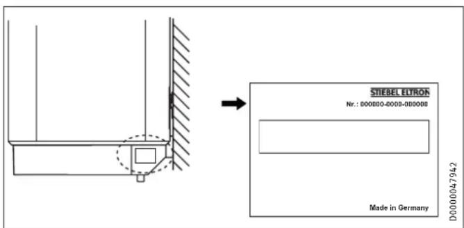
See type plate on the appliance.
3. Appliance description
The appliance electrically heats up domestic hot water with the standard heating output or with rapid heating. You can adjust the temperature using the temperature selector. Subject to the power supply, the water is automatically heated to the required temperature.
You can use the appliance in single circuit, dual circuit or instantaneous water cylinder mode.
The internal steel cylinder is coated in "anticor®" enamel and is equipped with a protective anode. The anode protects the internal cylinder from corrosion.
Frost protection
In single circuit and instantaneous water cylinder mode, the appliance is also protected against frost on the temperature setting "cold", as long as the power supply is guaranteed. The appliance switches on in good time and heats the water. The appliance does not protect the water supply lines and the safety assembly against frost. In dual-circuit operation, frost protection is only available during off-peak tariff periods.
Instantaneous water cylinder mode
In this operating mode, the appliance works with normal heating output when drawing off small amounts of water.
At high temperature settings and after large amounts of water have been drawn off, the appliance automatically switches over to booster heater (see chapter "Specification / Data table").
After the full amount of heated water in the cylinder has been drawn off, the appliance works in instantaneous mode with a booster heater. The available amounts of water that can be drawn off are reduced accordingly (see chapter "Specification / Output tables").
Following a longer power failure, the zero volt relay prevents the booster heater from being switched on straight away. Once the voltage returns, the appliance initially works with normal heating output until the temperature controller reacts for the first time. Subsequently, rapid heating is automatically ready for operation again.
Dual circuit operation
During off-peak tariff periods (power supply companies' cheap rate periods), the appliance automatically heats up the water content with standard heating output at all temperature settings. In addition, you can start the booster heater during peak tariff periods.
Single circuit operation
In this operating mode, the appliance heats up the water automatically subject to the connected heating output and temperature setting.
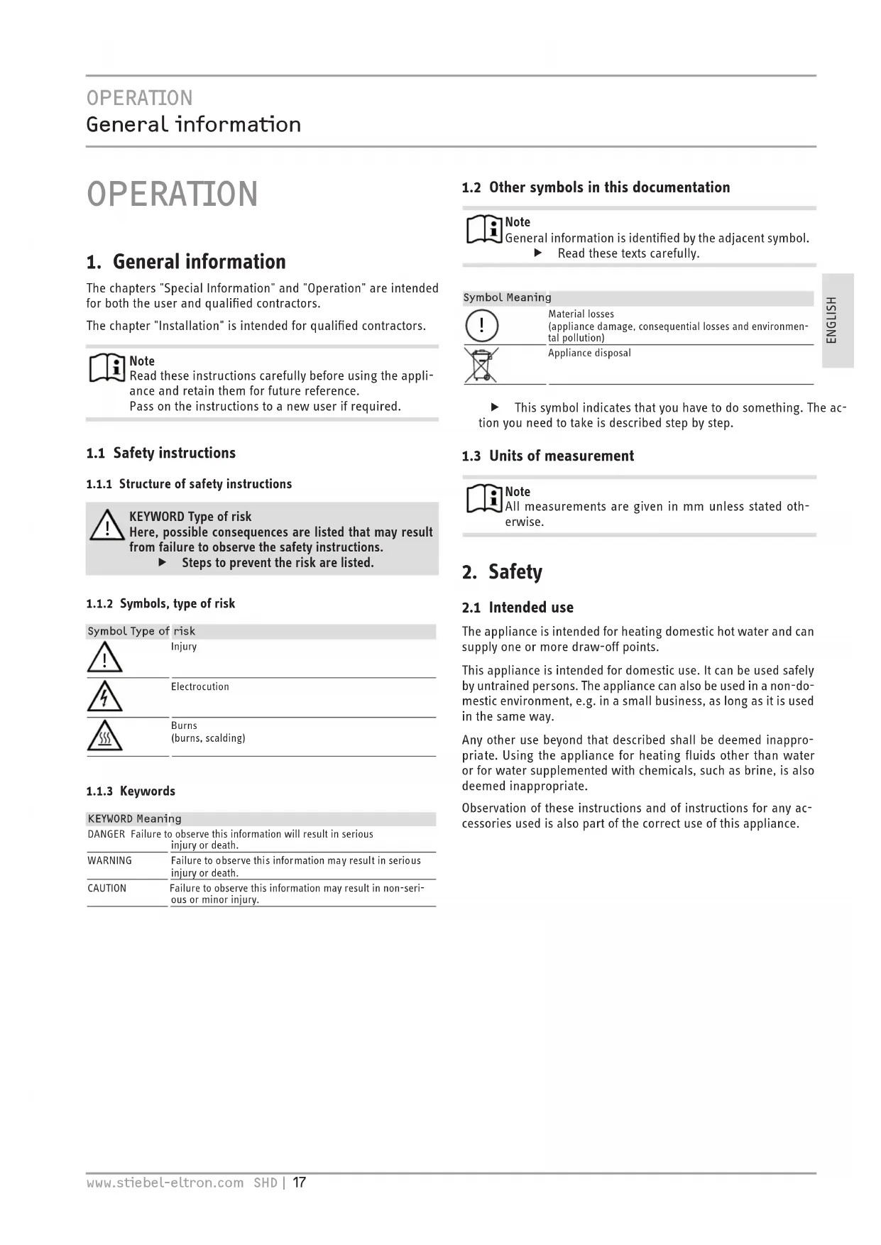
4. Settings
The temperature can be freely adjusted.
In single circuit and dual-circuit operation, the temperature setting can be limited by the qualified contractor (see chapter "Installation / Settings").
1 ON/OFF indicator for rapid heating
2 Rapid heating pushbutton (in dual-circuit operation)
3 Temperature selector
- Cold
E Recommended energy saving position, low scaling, 60 °C
85 °C Maximum temperature setting
4 "SERVICE ANODE" indicator
Depending on the system, the actual temperatures may vary from the set value.
ON/OFF indicator
The ON/OFF indicator light illuminates while the water is heated by the booster heater.
Rapid heating pushbutton in dual-circuit operation
You can switch on rapid heating with the pushbutton. A remote control can also be installed for this purpose. Rapid heating stops and will not restart when the selected temperature has been reached.
"SERVICE ANODE" indicator

Material losses
▶ Notify your qualified contractor if the SERVICE ANODE indicator illuminates.
Instantaneous water cylinder operation following a power failure
Following a longer power failure, you can switch the booster heater on manually straight away by first turing the temperature selector to the "cold" position and then up to 85 °C.
5. Cleaning, care and maintenance
▶ Have the electrical safety of the appliance and the function of the safety valve regularly checked by a qualified contractor.
The protective anode must be replaced by a qualified contractor as soon as the SERVICE ANODE indicator illuminates (see chapter "Maintenance / Replacing the protective anode").
▶ Never use abrasive or corrosive cleaning agents. A damp cloth is sufficient for cleaning the appliance.
Scaling
▶ Almost every type of water will deposit limescale at high temperatures. This settles inside the appliance and affects both the performance and service life. The heating elements must therefore be descaled from time to time. A qualified contractor who knows the local water quality will tell you when the next service is due.
▶ Check the taps regularly. Limescale deposits at the tap outlets can be removed using commercially available descaling agents.
▶ Regularly activate the safety valve to prevent it from becoming blocked, e.g. by limescale deposits.
6. Troubleshooting
| Problem Cause Remedy | ||
| The water does not heat up. | There is no power. | Check the fuses / MCBs in your fuse box/distribution panel. |
| The flow rate is low. | The aerator in the tap or the shower head is scaled up or contaminated. | Clean and/or descale the aerator or shower head. |
| SERVICE ANODE indicator illuminates. | Replace the protective anode. | Notify your qualified contractor. |
If you cannot remedy the fault, notify your contractor. To facilitate and speed up your enquiry, please provide the serial number from the type plate (000000-0000-000000):
INSTALLATION
7. Safety
Only a qualified contractor should carry out installation, commissioning, maintenance and repair of the appliance.
7.1 General safety instructions
We guarantee trouble-free function and operational reliability only if original accessories and spare parts intended for the appliance are used.
7.2 Instructions, standards and regulations

Note
Observe all applicable national and regional regulations and instructions.
8. Appliance description
8.1 Standard delivery
The following are delivered with the appliance:
- Wall mounting bracket
- 5 mm spacer (2 pce for above, 2 pce for below)
- Caps (2 pce)
- Installation template
8.2 Accessories
Required accessories
Various safety assemblies are available that need to be selected subject to the static pressure. These type-tested safety assemblies protect the appliance against impermissible excess pressure.
Further accessories
The load shedding relay activates the priority control during operation of the appliance when you are simultaneously operating another appliance, such as an electric storage heater (for connection, see chapter "Specification / Wiring diagrams and connections").
9. Preparations
9.1 Installation site
The appliance is designed for installation on a solid wall. Ensure the wall offers adequate load bearing capacity.
Install the appliance vertically in a room free from the risk of frost and near the draw-off point.
9.2 Fitting the wall mounting bracket
▶ You can use the installation template to transfer the dimensions to the wall.
▶ Drill the holes and secure the wall mounting bracket with screws and rawl plugs. Select fixing materials in accordance with the wall construction/condition.
You can compensate for unevenness in the wall with the spacers provided.
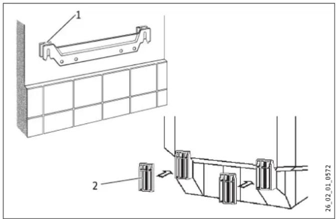
1 Upper spacer
2 Lower spacer
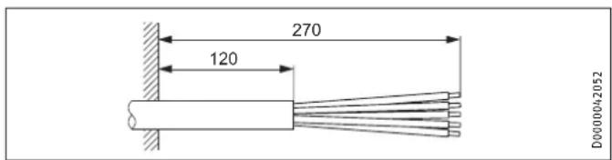
9.3 Preparing the power cable
10. Installation
10.1 Water connection

Material losses
Carry out all water connection and installation work in accordance with regulations.
- Connect the hydraulic connections with flat gaskets.
- Operate the appliance only with pressure-tested taps.
10.1.1 Permissible materials
Cold water line
Galvanised steel, stainless steel, copper and plastic are approved materials.
A safety valve is required.
DHW line

Material losses
The appliance is not suitable for the use of plastic piping for the DHW line.
Stainless steel and copper are approved materials.
The maximum permissible pressure must not be exceeded (see chapter "Specification / Data table").
10.1.2 Fitting the safety valve
▶ Install a type-tested safety valve in the cold water supply line. Please note that, depending on the static pressure, you may also need a pressure reducing valve.
▶ Size the drain pipe so that water can drain off unimpeded when the safety valve is fully opened.
▶ Fit the discharge pipe of the safety valve with a constant downward slope and in a room free from the risk of frost.
▶ The safety valve discharge aperture must remain open to atmosphere.
10.2 Appliance installation
▶ Hang the appliance on the wall mounting bracket.
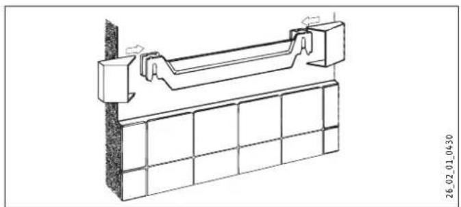
natural_image
Technical line drawing of a structural support frame with mounting bracket and grid base (no text or symbols)▶ Fit the caps.
10.3 Power supply

WARNING Electrocution
Carry out all electrical connection and installation work in accordance with relevant regulations.
Before any work on the appliance, disconnect all poles from the power supply.

WARNING Electrocution
The connection to the power supply is only permissible as a permanent connection in conjunction with the removable cable grommet. Ensure the appliance can be separated from the power supply by an isolator that disconnects all poles with at least 3 mm contact separation.

WARNING Electrocution
Ensure that the appliance is earthed.

Material losses
Install a residual current device (RCD).

Material losses
Observe the type plate. The specified voltage must match the mains voltage.
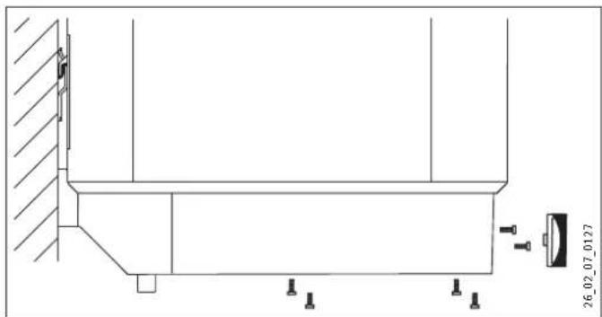
natural_image
Technical line drawing of a mechanical assembly with mounting holes and a scale (no text or symbols)▶ Pull off the temperature selector.
▶ Undo the screws.
▶ Remove the lower cap.
▶ Pull the cable grommet out downwards while pressing on the locking hooks.
▶ Push the cable grommet over the power cable and snap the cable grommet back in place.
Connect the required load in accordance with the wiring diagrams (see chapter "Specification / Wiring diagrams and terminals").
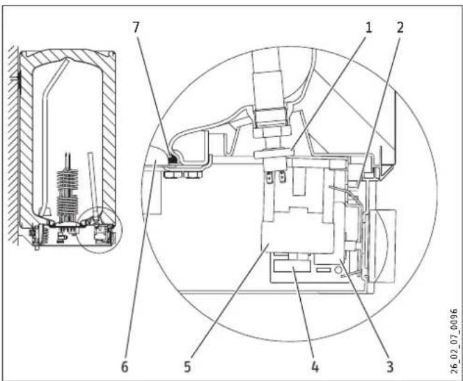
1 Pressure switch for protective anode
2 Operating mode switch
3 Temperature controller
4 Electronic assembly.
5 Contactor
6 Flange plate
7 Seal ring
▶ Select the operating mode using the switch:
Position I = Instantaneous water cylinder mode
Position II = Dual-circuit/single circuit operation
(see chapter "Specification / Wiring diagrams and connections").
▶ Fit the lower cap.
▶ Insert the screws.
▶ Push on the temperature selector.
▶ Tick the selected connected load and voltage on the type plate with a ballpoint pen.
- Connect the safety assembly to the appliance by screwing pipes onto the appliance.
11. Commissioning
11.1 Initial start-up
▶ Open a draw-off point until the appliance has filled up and the pipework is free of air.
▶ Adjust the flow rate. For this, observe the maximum permissible flow rate with a fully opened tap (see chapter "Specification / Data table").
▶ If necessary reduce the flow rate at the butterfly valve of the safety valve.
▶ Turn the temperature selector to maximum.
▶ Switch the mains power ON.
▶ Check the function of the appliance. Ensure that the temperature controller switches off.
▶ Check that the safety valve is working correctly.
11.1.1 Appliance handover
Explain the function of the appliance and safety assembly to users and familiarise them with their operation.
▶ Make the user aware of potential dangers, especially the risk of scalding.
▶ Hand over these instructions.
11.2 Recommissioning
See chapter "Commissioning / Initial start-up".
12. Settings
Limiting the temperature selection
Factory setting: 85 °C

Note
You can install a central thermostatic valve at the DHW outlet if the temperature selection limit is set to 85 °C. This enables the reduction of the outlet temperature.
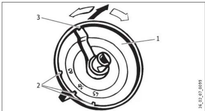
1 Temperature selector
2 The temperature selection limit can be adjusted to 45 °C, 55 °C or 65 °C.
3 85 °C
▶ Set the temperature selection limit.
13. Shutdown
▶ Disconnect the appliance from the mains at the MCB/fuse in the fuse box.
- Drain the appliance. See chapter "Maintenance / Draining the appliance".
14. Troubleshooting

Note
At temperatures below -15 °C the high limit safety cut-out may respond. The appliance may be subjected to these temperatures during storage or transport.
| Fault Cause Remedy | ||
| The water does not heat up. | The high limit safety cut-out has responded because the controller is faulty. | Remedy the cause of the fault. Replace the temperature controller. |
| The high limit safety cut-out has responded because the temperature has fallen below -15 °C. | Press the reset button (see diagram). | |
| Rapid heating does not switch on. | Test the pushbutton and lever. | |
| The flanged immersion | heater is faulty. | Replace the flanged immersion heater. |
| The selected outlet temperature is not reached during instantaneous water cylinder mode when the draw-off valve is fully opened. | More water flows through the appliance than the heating element can heat up. | Reduce the amount of water at the DHW valve. |
| The safety valve drips when heating is switched off. | The valve seat is contaminated. | Clean the valve seat. |
Reset button, high limit safety cut-out
1 High limit safety cut-out
2 Reset button
15. Maintenance

WARNING Electrocution
Carry out all electrical connection and installation work in accordance with relevant regulations. Before any work on the appliance, disconnect all poles of the appliance from the power supply.
For some maintenance work, the lower cap must be removed.
If you need to drain the appliance, observe chapter "Draining the appliance".
Note the insertion depths of the temperature controller (see chapter "Specification / Dimensions and connections").
15.1 Checking the safety valve
▶ Check the safety valve regularly.
15.2 Draining the appliance

WARNING Burns
Hot water may escape during the draining process.
If the appliance needs to be drained for maintenance or to protect the whole installation when there is a risk of frost, proceed as follows:
▶ Close the shut-off valve in the cold water inlet line.
▶ Open the hot water taps on all draw-off points.
natural_image
Technical diagram of a mechanical assembly with cross-sectional and top views (no text or symbols)1 Drain valve with hose connection G 3/4
▶ Screw a hose onto the drain valve.
▶ Open the drain valve.
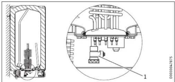
15.3 Replacing the protective anode
▶ If the SERVICE ANODE indicator illuminates, check the signal anode and replace if necessary. Spanner size for the anode
- SHD 30 S: SW 13
- SHD 100 S: SW 27
▶ When replacing the anode, take great care to fit the pressure switch on tightly (tighten by hand, torque value 100^+50 Ncm).
▶ Observe the maximum permissible transition resistance 1.0 Ω between the anode and the cylinder
15.4 Descaling
▶ Only descale the flange after disassembly.
▶ Never treat the cylinder surface or the protective anode with descaling agents.
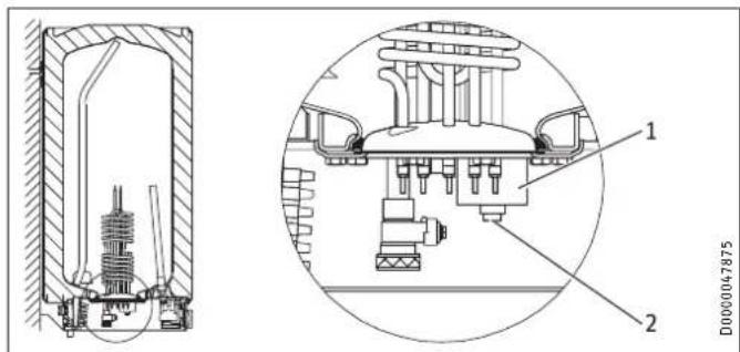
15.5 Anti-corrosion protection
When carrying out service work, ensure that the anti-corrosion protection on the insulating plate is not damaged or removed. Reinsert the anti-corrosion protection correctly after replacement.
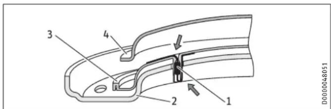
1 Anti-corrosion protection (390 Ω)
2 Pressure plate
3 Insulating plate
4 Flanged immersion heater
16. Specification
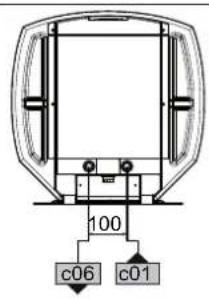
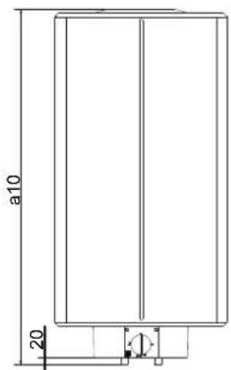
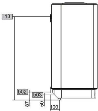
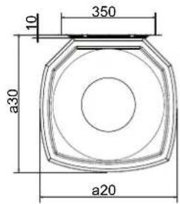
16.1 Dimensions and connections
D0000024812
| SHD 30 S SHD 100 S | |||||
| a10 | Appliance | Height | mm | 770 | 1050 |
| a20 | Appliance | Width | mm | 410 | 510 |
| a30 | Appliance | Depth | mm | 420 | 510 |
| b02 | Entry electrical cables I | ||||
| b03 | Entry electrical cables II | ||||
| c01 | Cold water inlet | Male thread | G 1/2 A | G 1/2 A | |
| c06 | DHW outlet | Male thread | G 1/2 A | G 1/2 A | |
| i13 | Wall mounting bracket | Height | mm | 700 | 900 |
| Max. ∅ fixing screw | mm | 12 | 12 | ||
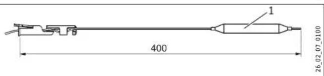
Immersion depth of thermostat sensor
1 Operating mode switch
2 Electronic assembly with zero volt and switching relay
3 Rapid heating pushbutton
4 Temperature controller
5 Pressure switch for protective anode
6 High limit safety cut-out
7 Heating element
Heating element
| 1 2 4 3 | ||||
| kW | 7.0 | 7.0 | 3.5 | 3.5 |
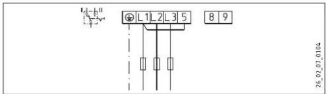
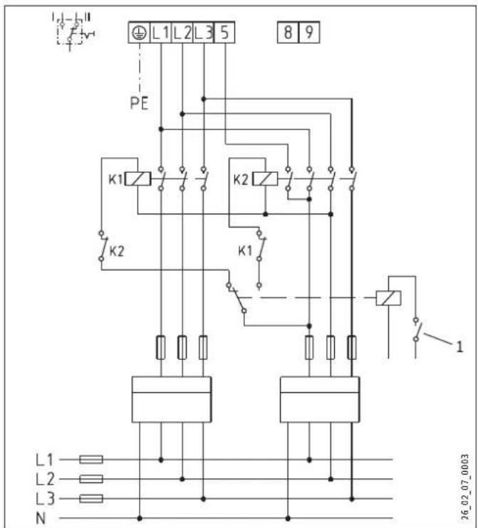
Instantaneous water cylinder mode
3.5/21 kW, 3/PE \~ 400 V
Dual circuit operation
Single-meter counting with power-OFF contact: 3.5/21 kW, 3/PE \~ 400 V
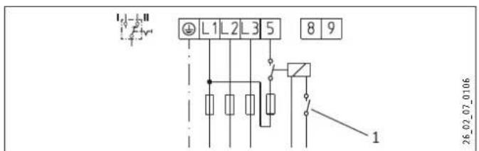
1 Power-OFF contact
Dual-meter measurement with power-OFF contact: 3.5/21 kW, 3/PE \~ 400 V
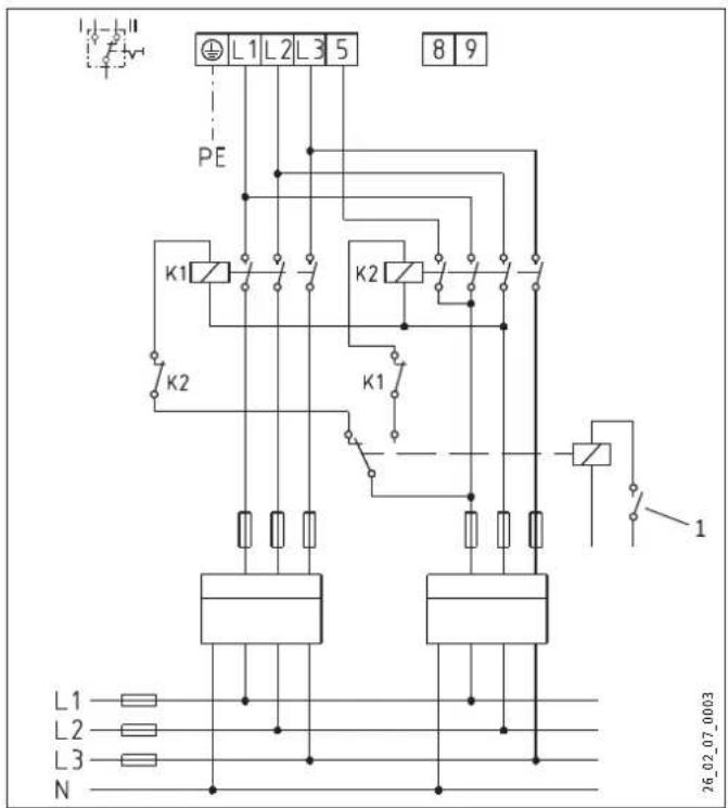
1 Power-OFF contact
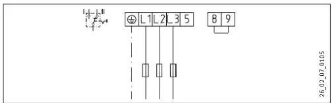
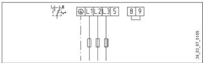
21 kW, 3/PE \~ 400 V
Single circuit operation
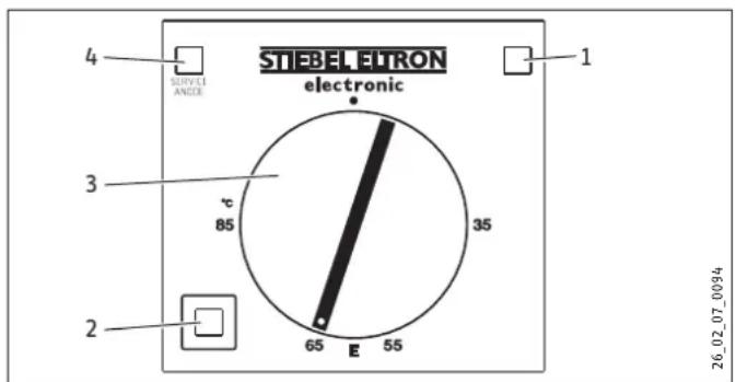
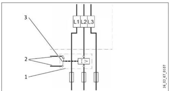
Load shedding relay LR 1-A

1 Load shedding relay
2 Control cable to the contactor of the second appliance
3 Control contact, opens when switching on the SHD S
16.3 Output tables
The heat-up time depends on the cylinder capacity, cold water inlet temperature and heating output. For the heat-up time with the booster heater (21 kW) and a cold water supply of 10 °C , see the following table.
| Heat-up time (cylinder operation) | |||
| Temperature setting range | °C | 65 | 85 |
| SHD 30 S min 6 8 | |||
| SHD 100 S min 18 25 | |||
In instantaneous DHW cylinder operation, the following amounts of hot water can be drawn off.
| DHW output (instantaneous operation) | |||
| DHW temperature | °C | 38 | 55 |
| Cold water supply 6 °C | l/min | 9.4 | 6.1 |
| old water supply 10 °C | l/min | 10.7 | 6.7 |
| old water supply 14 °C | l/min | 12.7 | 7.3 |
16.4 Fault conditions
In the event of a fault, temperatures of up to 130 °C at 0.6 MPa can occur.
16.5 Details on energy consumption
Product datasheet: Conventional water heaters to regulation (EU) no. 814/2013
| SHD 30 S | SHD 100 S | ||
| 073059 | 073060 | ||
| Manufacturer | STIEBEL ELTRON | STIEBEL ELTRON | |
| Load profile | S | L | |
| Energy efficiency class | B | C | |
| Energy conversion efficiency | % | 36 | 38 |
| Daily power consumption | kWh | 2.437 | 12.288 |
| Annual power consumption | kWh | 518 | 2666 |
| Default temperature setting | °C | 60 | 60 |
| Sound power level | dB(A) | 15 | 15 |
| Off-peak periods possible | Yes | Yes |
16.6 Data table
| SHD 30 S | SHD 100 S | ||
| 073059 | 073060 | ||
| Hydraulic data | |||
| Nominal capacity | l | 30 | 100 |
| Mixed water volume 40 °C (15 °C/65 °C) | l | 59 | 195 |
| Electrical data | |||
| Connected load ~ 400 V | kW | 3.5/21 | 3.5/21 |
| Phases | 3/PE | 3/PE | |
| Rated voltage | V | 400 | 400 |
| Frequency | Hz | 50 | 50 |
| Single circuit operating mode X | X | ||
| Dual circuit operating mode | X | X | |
| Application limits | |||
| Temperature setting range | °C | 35-85 | 35-85 |
| Max. permissible pressure | MPa | 0.6 | 0.6 |
| Test pressure | MPa | 0.78 | 0.78 |
| Max. permissible temperature | °C | 110 | 110 |
| Max. flow rate | l/min | 18 | 18 |
| Min./max. conductivity, drinking water | μS/cm | 100-1500 | 100-1500 |
| Energy data | |||
| Standby energy consumption/24 h at 65 °C | kWh | 0.46 | 0.86 |
| Energy efficiency class | B | C | |
| Versions | |||
| IP rating | IP25 | IP25 | |
| Sealed unvented type | X | X | |
| Colour | White | White | |
| Dimensions | |||
| Height | mm | 770 | 1050 |
| Width | mm | 410 | 510 |
| Depth | mm | 420 | 510 |
| Weight | |||
| Weight, full | kg | 54.3 | 140.1 |
| Weight, empty | kg | 24.3 | 40.1 |
Guarantee
The guarantee conditions of our German companies do not apply to appliances acquired outside of Germany. In countries where our subsidiaries sell our products a guarantee can only be issued by those subsidiaries. Such guarantee is only granted if the subsidiary has issued its own terms of guarantee. No other guarantee will be granted.
We shall not provide any guarantee for appliances acquired in countries where we have no subsidiary to sell our products. This will not affect warranties issued by any importers.
Environment and recycling
We would ask you to help protect the environment. After use, dispose of the various materials in accordance with national regulations.
REMARQUES PARTICULIÈRES
UTILISATION
natural_image
Technical line drawing of a structural support frame assembly (no text or symbols)▶ Montez les caches.
natural_image
Technical line drawing of a mechanical assembly with mounting holes and a scale (no text or symbols)natural_image
Technical diagram of a mechanical assembly with cross-sectional and top views (no text or symbols)WAARSCHUWING verbranding
natural_image
Technical line drawing of a structural component with mounting bracket and grid base (no text or symbols)▶ Monteer de afdekkappen.
natural_image
Technical line drawing of a mechanical assembly with mounting holes and a scale (no text or symbols)WAARSCHUWING verbranding
natural_image
Technical diagram of a mechanical assembly with cross-sectional and top views (no text or symbols)- SHD 30 S: SW 13
- SHD 100 S: SW 27
Lastafwerprelais LR 1-A
natural_image
Technical line drawing of a structural support frame with mounting brackets and grid panels (no text or symbols)natural_image
Technical line drawing of a mechanical assembly with mounting holes and a scale marker (no text or symbols)natural_image
Technical diagram of an electrical enclosure and its internal components, showing internal structure and assembly (no text or symbols)Dvouokruhový provoz
1 Kontakt HDO
natural_image
Technical line drawing of a structural support frame with mounting bracket and grid base (no text or symbols)natural_image
Technical line drawing of a mechanical assembly with mounting holes and a scale indicator (no text or symbols)natural_image
Technical diagram of a mechanical assembly with cross-sectional and top views (no text or symbols)- SHD 30 S: SW 13
- SHD 100 S: SW 27
natural_image
Technical line drawing of a structural joint or bracket assembly (no text or symbols present)natural_image
Technical line drawing of a mechanical assembly with mounting holes and a scale (no text or symbols)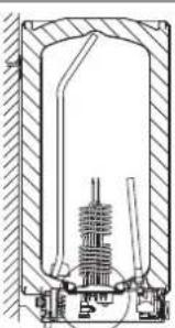
natural_image
Cross-sectional technical drawing of a mechanical assembly (no visible text or labels)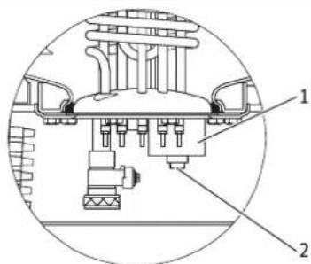
D0000047875
natural_image
Technical diagram of a mechanical assembly with cross-sectional and top views (no text or symbols)- SHD 30 S: SW 13
- SHD 100 S: SW 27
Tryb dwutaryfowy
1 Styk ZE
natural_image
Technical line drawing of a structural support frame with mounting bracket and grid base (no text or symbols)▶ Namontujte krycie uzávery.
natural_image
Technical line drawing of a mechanical assembly with mounting holes and a scale (no text or symbols)natural_image
Technical line drawing of a mechanical assembly with cross-sectional and top views (no text or symbols)Dvojokruhový režim
1 Kontakt dodávatel'a elektrickej energie
Meranie dvomi elektromermi s kontaktom dodávatelá elektrickej energie: 3,5 / 21 kW, 3/PE \~ 400 V
1 Kontakt dodávatel'a elektrickej energie
Jednookruhový režim
21 kW, 3/PE \~ 400 V
Relé poklesu zataženia LR 1-A
![3 L1 L2 L3 2 1 [ > ] 26_02_07_0107](/content/2026/03/486416/images/6440a4423e89ee95d09ffa24eac94cfe84cbfd954bb3f3f8177ca91679fd1879.jpg)
6 Prohasky Street | Port Melbourne VIC 3207
Tel. 03 9645-1833 | Fax 03 9645-4366
info@stiebel.com.au
www.stiebel.com.au
Austria
STIEBEL ELTRON Ges.m.b.H.
Plant C3, XEDA International Industry City
Xiqing Economic Development Area
300085 Tianjin
Tel. 022 8396 2077 | Fax 022 8396 2075
info@stiebeleltron.cn
www.stiebeleltron.cn
Czech Republic
STIEBEL ELTRON spol. s r.o.
K Hájüm 946 | 155 00 Praha 5 - Stodülky
Tel. 251116-111 | Fax 235512-122
Urzhumskaya street 4,
building 2 | 129343 Moscow
Tel. 0495 7753889 | Fax 0495 7753887
info@stiebel-eltron.ru
www.stiebel-eltron.ru
Slovakia
TATRAMAT - ohrievače vody s.r.o.
Hlavná 1 | 058 01 Poprad
Tel. 052 7127-125 | Fax 052 7127-148
info@stiebel-eltron.sk
www.stiebel-eltron.sk
Switzerland
STIEBEL ELTRON AG
Industrie West
Gass 8 | 5242 Lupfig
Tel. 056 4640-500 | Fax 056 4640-501
info@stiebel-eltron.ch
www.stiebel-eltron.ch
Thailand
STIEBEL ELTRON Asia Ltd.
469 Moo 2 Tambol Klong-Jik
Amphur Bangpa-In | 13160 Ayutthaya
Tel. 035 220088|Fax 035 221188
info@stiebeleltronasia.com
www.stiebeleltronasia.com
United Kingdom and Ireland
STIEBEL ELTRON UK Ltd.
Unit 12 Stadium Court
Stadium Road | CH62 3RP Bromborough
Tel. 0151 346-2300 | Fax 0151 334-2913
info@stiebel-eltron.co.uk
www.stiebel-eltron.co.uk
United States of America
STIEBEL ELTRON, Inc.
17 West Street | 01088 West Hatfield MA
Tel. 0413 247-3380 | Fax 0413 247-3369
info@stiebel-eltron-usa.com
www.stiebel-eltron-usa.com

Irrtum et de technische Änderungen vorbehalten! | Subject to errors and technical changes! | Sous réserve d'erreurs et de modifications techniques! | Onder voorbehoud van vergissingen en technische wijzigingen! | Salvo error o modificación técnica! | Excepto erro ou alteração técnica | Zastrzeżone zmiany techniczne i ewentualne błędy | Omyly a technické zmény jsou vyhrazeny! | A muszaki változtalások és têvedések jogát fenntartjuk! | Otcutствие ошибok ne гарантируется. Возможны технические изменения. | Chyby a technické zmény sú vyhradené! Stand 9375
STIEBEL ELTRON