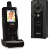
DoorPhone 170 - Intercom MARMITEK - Free user manual and instructions
Find the device manual for free DoorPhone 170 MARMITEK in PDF.
User questions about DoorPhone 170 MARMITEK
0 question about this device. Answer the ones you know or ask your own.
Ask a new question about this device
Download the instructions for your Intercom in PDF format for free! Find your manual DoorPhone 170 - MARMITEK and take your electronic device back in hand. On this page are published all the documents necessary for the use of your device. DoorPhone 170 by MARMITEK.
USER MANUAL DoorPhone 170 MARMITEK
natural_image
Black rectangular electronic device with a bell icon and 'MARINITEK' logo, no visible text or symbols on the device itself.USER MANUAL 3
STANDARD ACCESSORIES....5
GETTING STARTED 6
POWER SUPPLY 6
DOOR UNIT....6
HANDSET....7
PAIRING THE HANDSET AND DOOR UNIT 8
MOUNTING OF DOOR UNIT....10
Always close 11
Always open....11
Auxiliary terminal....11
CONTROLS LAYOUT 12
LCD 13
OPERATION 16
GATE VOLUME....16
ALARM MODE 16
TRIGGER TIME....16
DOOR LOCK OPEN....17
INTERCOM....20
PRECAUTION....20
TROUBLE SHOOTING GUIDE....21
TECHNICAL DATA 22
INTRODUCTION
Thank you for purchasing this Digital Wireless Doorphone System. Your system has been manufactured and checked under the strictest possible quality control to ensure that each system leaves the factory in perfect condition. In the unlikely event you find any defect or experience any problem, please contact our service centre or dealer, do not attempt to repair by yourself.
Please read this manual carefully to obtain optimum performance and extended service life from the system.
SAFETY WARNINGS
- Do not expose the components of your system to extremely high temperatures or bright light sources.
- In case of improper usage or if you have altered and repaired the product yourself, all guarantees expire. Marmitek does not accept responsibility in the case of improper usage of the product or when the product is used for purposes other than specified. Marmitek does not accept responsibility for additional damage other than that covered by the legal product responsibility.
• This product is not a toy. Keep out of reach of children.
- Do not open the product (battery panel excepted): the device may contain live parts. The product should only be repaired or serviced by a qualified expert.
- Keep batteries out of the reach of children. Dispose of batteries as chemical waste. Never use old and new batteries or different types of batteries together. Remove the batteries when you are not using the system for a longer period of time. Check the polarity (+/-) of the batteries when inserting them in the product. Wrong positioning can cause an explosion.
- Only connect the adapter to the mains after checking whether the mains voltage is the same as the values on the identification tags. Never connect an adapter or power cord when it is damaged. In that case, contact your supplier.
FEATURES
• Digital transmission ensures interference-free conversation
- Two way communication
- Long operating range of 300m in open space
- Selectable audio, visual or vibration alert for doorbell
- Remote control of electric door lock
- The door unit is provided with an extra AUX _AUX connector which gets activated when the doorbell button is pressed. Among other functions, this can be used for the activation of an (existing) conventional doorbell or for switching on the lights in the door/entrance.
• Audible and visual alert for out-of-range and low battery level
- Intercom function between handsets
- Door unit complies to IP54 standard
• Extremely easy installation without any wiring needed
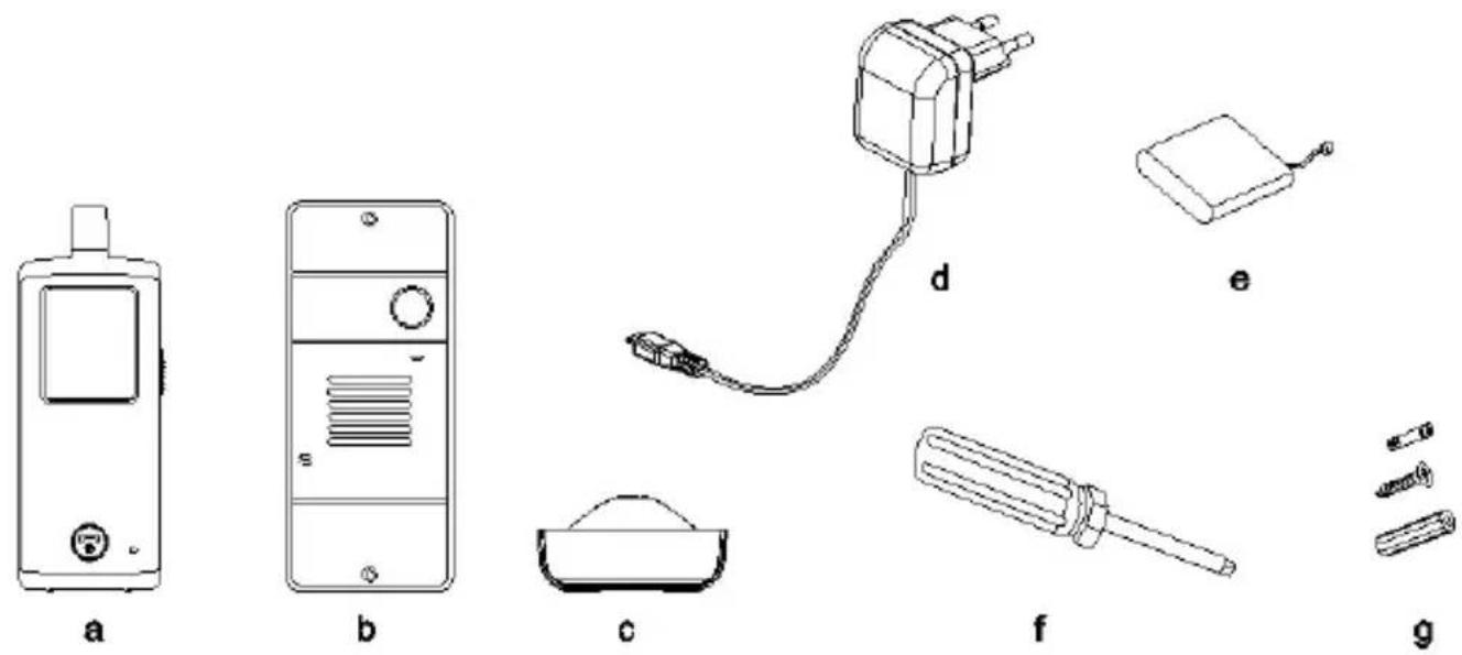
STANDARD ACCESSORIES
text_image
a b c d e f g
text_image
DOORPHONE 170 SUSUCTION ANUK ha. Handset
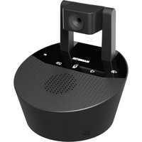
b. Door unit
c. Charger stand
d. Switching power supply
e. Rechargeable Li
f. Tool
g. Screws and rivets
h. Instruction manual
battery pack (installed in handset)
GETTING STARTED
POWER SUPPLY
DOOR UNIT
The door unit can be powered in two ways.
-
Using batteries. (power failure)
-
Using external power adapter.

natural_image
Technical line drawing of a device casing with internal components and mounting holes (no text or symbols)
natural_image
Technical line drawing of a remote control box with labeled components (no text or symbols beyond labels)-
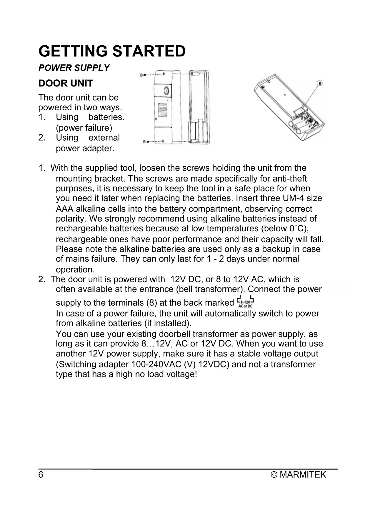
With the supplied tool, loosen the screws holding the unit from the mounting bracket. The screws are made specifically for anti-theft purposes, it is necessary to keep the tool in a safe place for when you need it later when replacing the batteries. Insert three UM-4 size AAA alkaline cells into the battery compartment, observing correct polarity. We strongly recommend using alkaline batteries instead of rechargeable batteries because at low temperatures (below 0°C), rechargeable ones have poor performance and their capacity will fall. Please note the alkaline batteries are used only as a backup in case of mains failure. They can only last for 1 - 2 days under normal operation.
-
The door unit is powered with 12V DC, or 8 to 12V AC, which is often available at the entrance (bell transformer). Connect the power supply to the terminals (8) at the back marked 8-12V AC or DC
In case of a power failure, the unit will automatically switch to power from alkaline batteries (if installed).
You can use your existing doorbell transformer as power supply, as long as it can provide 8...12V, AC or 12V DC. When you want to use another 12V power supply, make sure it has a stable voltage output (Switching adapter 100-240VAC (V) 12VDC) and not a transformer type that has a high no load voltage!
HANDSET
natural_image
Technical line drawings of a mobile phone case with labeled components (no text or symbols beyond numbers)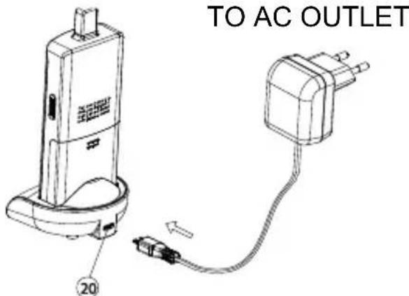
text_image
TO AC OUTLET 20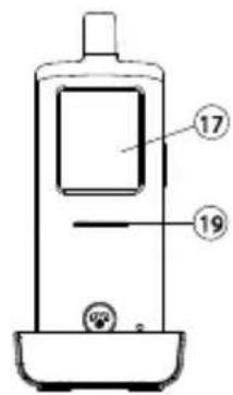
text_image
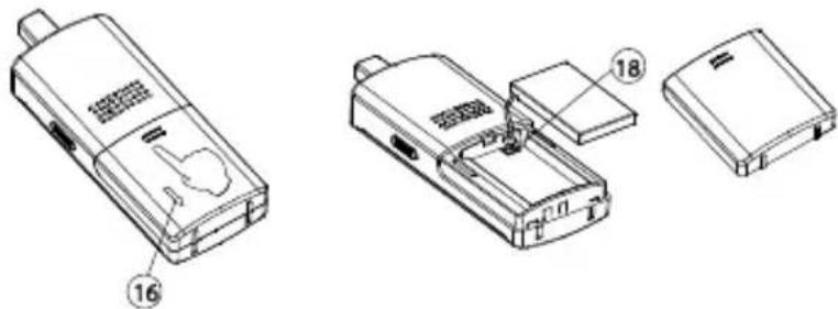
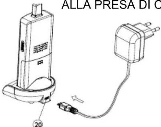
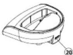
Technical diagram of a mobile phone with labeled parts 17 and 19, showing front panel and control buttons.- The supplied Li polymer battery pack is already installed in the handset. (To replace, press down the lock button (16) and slide open the battery door, take out the battery pack and disconnect from the socket (18).)
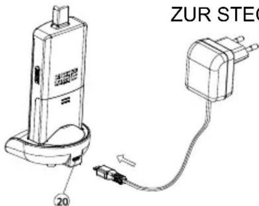
- With the handset remaining switched off, place it onto the charger stand.
- Plug in the supplied AC power supply into an AC outlet and connect its output plug to the USB port (20) located at the back of the charger stand.
- The charging indicator (19) should light up red during the charging process. Adjust the position of the handset in the charger stand in case this indicator does not light up. During charging, the battery level icon P will show up in LCD and the segments inside the icon will flash in turn.
- The battery pack should be fully charged within 4 hours when used for the first time. The power indicator (19) will now go off (if the handset is switched off) or turn steady blue (if the handset is switched on)..
- Now the unit can be switched on and ready for operation. Taking out the unit or keeping it placed in the charger stand will cause no damage to the battery. In the latter case, when the battery is being consumed and the voltage falls to a certain level, the charger stand will automatically charge up the battery.
CAUTION: BE SURE THE BATTERY IN THE HANDSET IS A RECHARGEABLE TYPE BEFORE YOU PLACE IT IN THE CHARGER STAND, OTHERWISE AN EXPLOSION MAY RESULT.
PAIRING THE HANDSET AND DOOR UNIT
This process is to match the door unit with the handset so that they can communicate with each other and so that no other devices (even a door phone of an identical model) can interfere with you or the receiving of your signal.
The door unit and handset are already paired with a factory pre-set code when they are shipped from the factory. However, we recommend pairing them again to achieve better privacy and to avoid a false triggering of a door lock from a nearby door phone system.
To perform the pairing process, it is necessary to use alkaline batteries as the power supply in the door unit, while the12V DC supply should be disconnected temporarily.
- Place the door unit and handset close to each other within a distance of 1m.
- Press and hold the talk/answer button 📋 (16), then long press the
power ON/OFF button 🔒 (15) to switch on the unit. The screen (17) will show the following:

text_image
Flashing Light up steady
text_image
PAIRING- Press and hold the pairing button (7) at the back of the door unit while installing the alkaline batteries. The call indicator (4) will start flashing after 3 sec, showing that the door unit has entered pairing mode.
Perform the same for the door unit that is intended to be used at the back gate (option, not included).
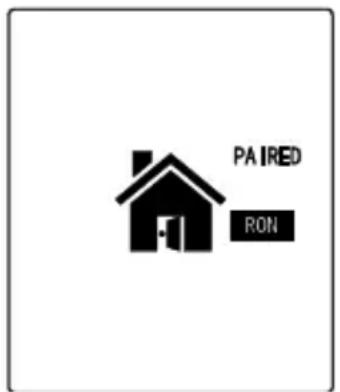
- Now release the pairing button (7), press call button (1) 📋 on the front gate door unit (DO NOT press the call button on the back gate door unit). Two “Di Di” sounds will be heard. The screen (17) will show the following once pairing is successful:
text_image
PAIRED RON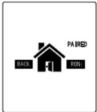
text_image
PAIRED BACK RON(in case there is a back gate door unit)
The call indicator (4) on both front gate & back gate door units should stop flashing and remain steady on.
-
Long press the Power ON/OFF button (15) to switch off the handset. Take out the alkaline batteries from the door unit and then re-install again or connect to the power supply.
-
The doorphone is now ready for operation. If the pairing process is not successful (the "PAIRING" continues to flash in the LCD of the handset), repeat the procedures from step 1 again.
N.B. In case you are having two or more handsets as well as a back gate door unit, always perform the pairing process with all door units and handsets together and with the handsets being set in pairing mode first. Remember every time you add on new units to the system, either handset or door unit (for back gate use), it is necessary to perform the pairing process all over again with all the units together or otherwise the new units will not work with your original DoorPhone 170.
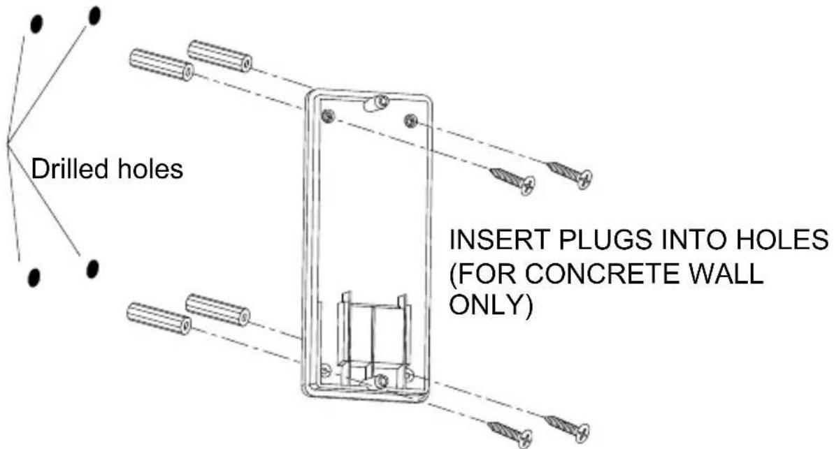
MOUNTING OF DOOR UNIT
text_image
Drilled holes INSERT PLUGS INTO HOLES (FOR CONCRETE WALL ONLY)- Select a location near your door entrance where the surface is not too rough. We recommend that you do some polishing to get a plane surface or otherwise the unit may not be able to mount properly. It should be noted that the mounting bracket should not be installed on metal screening surfaces or in the vicinity of other electronic devices that may reduce the operating range. Using the supplied self-tap screws, fix the mounting bracket onto the wall.
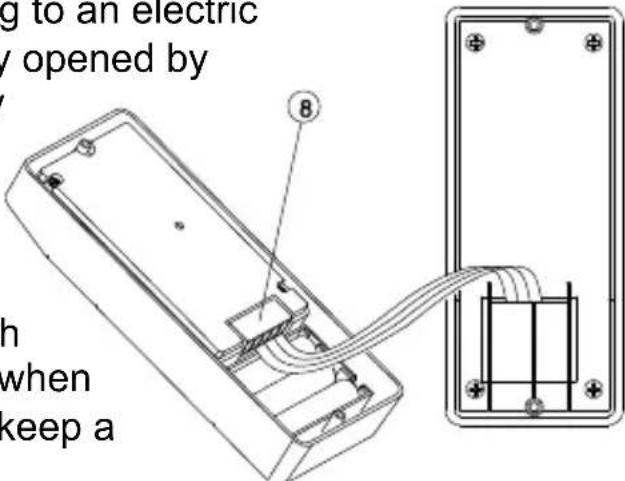
- In case there is a 12V DC supply, connect to the terminals marked at the back of the door unit. In addition, there are also terminals
marked ⏻ and ⏱ for connecting to an electric
door latch which can be remotely opened by
the handset. Where a DC supply is available, the call button (1)
will be automatically illuminated once the environment gets dark. This feature and the electric door latch opening feature will not operate when using alkaline batteries so as to keep a long battery life.
text_image
g to an electric y opened by 8 h when keep aCAUTION: When using a DC supply, in case the electric door latch does not function, reverse the polarity it is connected to and try again.
The two most common types of electric door latches on the market are either “always close” or “always open”.
Always close
These two terminals normally provide a 12V supply. During communication, once the door lock opening button ⑬ is pressed, this voltage will drop to 0V temporarily for duration of time as specified by the TRIGGER TIME function.
Always open
These two terminals normally provide 0V. During communication, once the door lock opening button (13) is pressed, the terminals will provide a 12V supply temporarily for duration of time as specified by the TRIGGER TIME function.
Under no circumstances should AC mains Voltage be directly connected to the terminal blocks (8)!
Auxiliary terminal
These two terminals act like a switch and will be short circuited as long as the doorbell button ⏱(1) is pressed, however, there is no voltage supply from these terminals. They can be used to trigger a conventional door chime or a courtesy light at the entrance.
- Now insert the 3 pcs AAA (UM-4) alkaline batteries into the battery compartment as this can serve as a battery back-up in case the 8 - 12V power supply fails.
natural_image
Technical line drawing of a device with internal components and directional arrows (no text or symbols)TO DC SUPPLY AND ELECTRIC DOOR LOCK
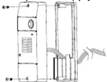
- Install the back of the door unit onto the mounting bracket using the supplied tool.
- The door unit is housed in a high impact ABS/PC cabinet which can achieve the professional grade ruggedness required in most outdoor applications. Rubber gaskets seal around all of the joints to keep out dust, rain and snow, assuring years of reliable operation even in harsh environments. The unit meets IP-54 standard and can operate from -20°C to 50°C.
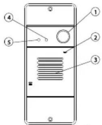
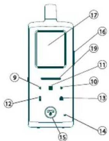
CONTROLS LAYOUT
text_image
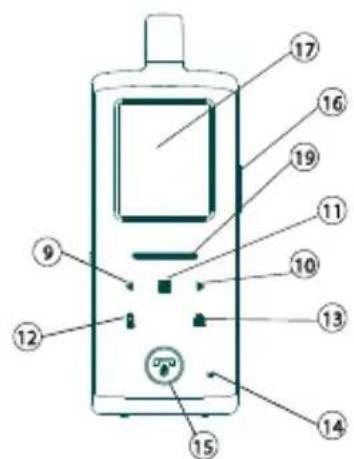
Diagram of a mobile phone front panel with numbered labels pointing to different compartments or ports.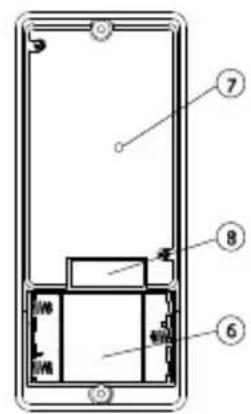
text_image
Diagram of a smartphone front panel with numbered components labeled 6, 7, and 8Door unit
text_image
Diagram of a mobile phone with numbered parts for identification and labeling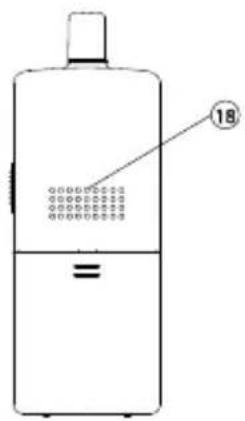
text_image
18Handset

natural_image
Technical line drawing of a mechanical component with no visible text or symbolsCharging Stand
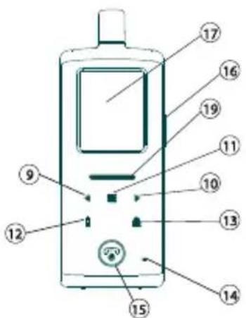
- Call button
- Microphone
- Speaker
- Call indicator
- Light sensor
- Alkaline battery compartment
- Pairing button
- Terminal block
- Volume down key
- Volume up key
-
Menu key
-
Handset Call key
- Door lock open button
- Microphone
- Hang up and power ON/OFF button
- Talk and answer button
- LCD
- Speaker
- Power and battery low indicator
- USB port
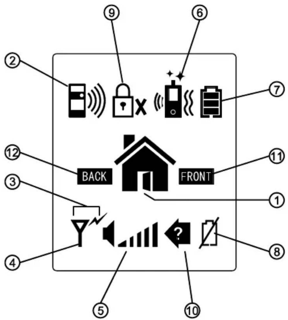
LCD
flowchart
graph TD
    A["Device"] --> B["Back"]
    C["Lock"] --> D["Front"]
    E["Monitor"] --> F["Front"]
    G["Speaker"] --> H["Back"]
    I["Signal"] --> J["Front"]
    K["Check"] --> L["Back"]
    M["Display"] --> N["Front"]
    O["Monitor"] --> P["Back"]
    Q["Signal"] --> R["Front"]
- Door lock opened
- Doorbell ringing
- Transmit icon
- Reception mode Out of range icon
- Speaker volume bar graph
- Door chime, flashing light and vibrating alert selected
- Battery Level indicator
- Door unit battery low
- Door lock de-activated
- Missed call
- Front gate
- Back gate
Flashing Steady light up
A. Front gate doorbell ringing
B. Back gate doorbell ringing
C. (Front Back) Missed call,
D. Y Reception mode
E. Out of range alert (Front gate) FRONT BACK (Back gate)
F. Door chime alert selected
G. Flashing light alert selected
H. Vibrating alert selected
I. Doorchime and flashing light alert selected
J. Door time and
vibrating alert selected

Flashing light and vibrating alert selected
Door chime, flashing light and vibrating alert selected

Door unit battery low ont FRONT) BACK (Back gate)
Handset battery low

Handset Battery level

Speaker volume

R. Door lock de-activated
OPERATION
- Switch on the handset with a long press (over 3 seconds) of the Power ON/OFF button (15). Press the same button again in case you want to switch off the unit.
- The power indicator (19) will light up blue. In case the Li battery has run down, the power indicator will start flashing blue. At the same time, the battery icon shown on the LCD (17) will become empty and flashing. Place the unit into the charger stand to charge up the battery. During charging, the segments inside the battery level icon P will flash in turn irrespective if the unit is switched on or off. To protect the battery, if the unit is not being re-charged when the icon O shows up, it will be switched off automatically after 10 minutes.
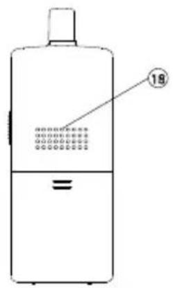
- During standby mode, short press of the Talk/answer button 📋/f (16) will initiate the backlight and activated the touch keys Long touch the menu key ≡ (11) for over 3 sec to enter programming mode & LCD show following:
GATE VOLUME
This will set the speaker volume of the door unit. Use the left/right key◀▶ (9) (10) to select between the 4 levels with 1 being the lowest and 4 being the highest volume. Short touch the menu key ≈1) to confirm your setting.
natural_image
Simple icon with a black square containing the letter 'B' and green Wi-Fi signal waves, no text or symbols present.ALARM MODE
This will set the method of alert when a visitor calls, either with a ding-dong sound or vibration or both. Use the left/right key ◀▶(9) (10) to select between 📞 (ding-dong sound and vibration) or (ding-dong sound only) or 📄(vibration only). Short touch the menu key ≡ (11) to confirm.
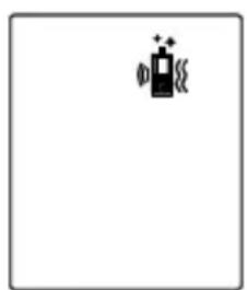
natural_image
Simple icon of a battery with charging symbol and sparkles, no text or labels presentThe corresponding icon will be shown on the top of the LCD (18).
TRIGGER TIME
This is the duration time for how long the door lock is being triggered. Use the left/right key ◀▶(9) (10) to select between 2, 8, 15, or 30 seconds. Short touch the menu key ≈1) to confirm.
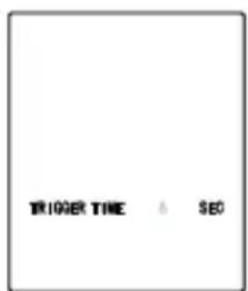
text_image
TRIGGER TIME & SEODOOR LOCK OPEN
This is to activate or deactivate the door lock open key 🔒(13). Use the left/right key ◀9) (10) to select between “ACTIVATE” or “DEACTIVATE”, Short touch the menu key ≡(11) to confirm. In case DEACTIVATE is selected, the icon ⏻Xwill show up at the top part of the LCD (17).
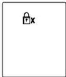
natural_image
Simple icon of a padlock with 'x' label, no text or symbols presentTo return to standby mode, short press the power/hang up button 🔒(15). Alternatively, if no key is being touched for over 1 min, the handset will return to standby mode automatically.
-
During conversation, the sound volume heard through the speaker (18) can also be adjusted using buttons ◀▶ 9 & 10 and the speaker volume bar graph will change correspondingly. Please note the loudness of door chime is fixed and cannot be adjusted.
-
Make sure there is a power supply to the door unit (either by 12V DC or alkaline batteries). Now press the Call button (1) 🔔, a ding-dong tone will be heard and the Call indicator (4) will start to flash. Until a handset answers the call, the ding-dong tone will be heard periodically, reminding the visitor to keep waiting. In case there is no answer after 20 seconds, the door unit will end the call by itself and the Call indicator (4) will go off. Press the Call button (1) 🔔 to initiate the call again.
N.B. In case there are two door units (front gate and back gate), only the unit whose call button (1) 📋 is pressed first will send out a call signal to the handset, the remaining unit will remain in standby mode until the conversation is over. If its call button (1) 📋 is pressed during this period, a “Be-Be” sound will be heard and the call indicator (4) will flash two times, indicating the unit is in standby mode.
-
Once the call is answered, the Call indicator (4) will light up steady and the ding-dong tone will stop ringing. Conversation can now be conducted by speaking into the Microphone (2)
-
Upon receiving a call, either icon A or icon B will appear on the screen, depending if the call is from the front gate or back gate (in case you have purchased an optional door unit for back gate). The handset can answer the call by pressing the Answer button (16) and the reception mode icon D will show up in LCD.
Now conversation is possible and the voice of the visitor can be heard from the speaker (18). To talk back to the visitor, press and hold the PTT button (16) 📋 and speak towards the Microphone (14), the transmit mode 🌐 shows up. Release the PTT button
(16) after finish speaking to listen to the visitor, the reception mode icon D will show up again. It should be noted that the voice of the visitor will not be heard while pressing the PTT button (16). Upon finishing the conversation, press the Hang up button (15) to end the call.
The DoorPhone 170 has an automatic end call feature. In case the resident does not talk back to the visitor (i.e. press the PTT button (16) for more than 90 sec, the call will be ended automatically. This feature is useful for protecting your privacy in case you forget to end the call by pressing the Hang up button (15).
- Once a call has been answered, you can use the door lock open button (13) 🔒 to remotely open the electric door latch for the visitor (this function is only available if there is a 12V DC supply to the door unit and your door is equipped with an electric latch). Touch and hold the button (13) 🔒 for over 2 seconds, wait a while and the icon M 📋 will appear on the screen, showing that the door latch is open. The icon M 📋 will disappear after a duration as specified by the trigger time function.
Under standby mode (i.e. when no call is set up between the handset and door unit), the electric door latch of the front door can also be opened by a long press of button (13) for over 2 sec. The Call indicator (4) on the door unit also lights up for a duration as specified by the trigger time function.
To avoid misuse by children, this door lock opening function can be activated or deactivated. When deactivated, as indicated by the 📄x on the LCD (17), pressing the button (13) 🔒 will have no effect.
- For systems equipped with several handsets, all the handsets will be alerted of an incoming call. However, only the handset which first presses the Answer button (16) 📞/ 📞 can set up conversation with the door unit. The remaining handsets will return to standby mode and their buttons will become de-activated until the conversation ends, making it impossible for them to interfere with the conversation.
- Under the circumstances of an unanswered call from a visitor (e.g. you are away from home or located at a place which is out of range from the door unit), the icon C will appear on the screen. This icon is useful to remind you that somebody has called. Press any button momentarily to remove this icon.
- Whenever the handset is located at a spot which is outside of the communication range of the door unit (either front or back gate), an alarm will be heard and the icon E = will appear on the screen. Such an alarm is not immediate and it will alert you only when you are out of range for over 2 minutes (when the 12V DC supply is
available or 20 minutes if the battery is used). Pressing the talk/answer button (16) 📞/ or the hang up button (15) 🔍 momentarily can stop the alarm but the icon E 📄 will still remain. Once the handset falls back in range, the alarm will stop and the icon E 📃 will disappear.
N.B. This out of range alert will also occur in case the batteries of the door unit run down and its DC power is cut off.
- Under normal operation, the back-up alkaline batteries inside the door unit (we suggest using good quality batteries such as Duracell) can last for 2-3 days. When there is no 12V DC supply and the backup batteries become run down, the icon N 📁 will appears on the screen and an alarm will be heard, reminding you to replace it with new batteries in the respective door unit. Pressing the talk/answer button (16) 📋 or the hang up button (15) 📄 momentarily can stop the alarm but the icon N 📁 will still remain until new batteries are installed.
N.B. In case the handset is out of range and the door unit battery goes low at the same time, then only the out of range icon E is shown and its alarm will be heard.
-
Whenever the buttons (except the PTT button (16) 📋/阀门) or hang up button (15) 🔒 on the handset are pressed, a tone will be heard to validate your entry.
-
Once the Light sensor (5) detects a low light intensity, the Call button (1) 📋 on the door unit will become automatically backlighted (only if a12V DC supply is available).
INTERCOM
This function is applicable only if you have two or more handsets. Please note all units must be paired together.
a. Under standby mode, touch and hold the handset call key (12), a "do – do" sound will be heard.
b. The called handset will show the selected incoming call alert. Press the Answer button (16) 📋/ 🔍 to answer the call. The “do-do” sound on the calling handset will stop.
c. Now both handsets can converse with each other using the Answer button (16) 🔔/√.
d. Either party can press the Hang up button (15) to end the conversation.
e. The call will also be ended automatically if the PTT button (16) 📞//
on either party is not pressed for over 60 sec.
For systems with more than two handsets, the incoming call alert on the remaining handsets will stop once the call is answered. In case nobody answers the call, the alert will stop 20 seconds later.
N.B. Selective calling of a particular handset is not possible. Whenever a handset initiates a call, all of the remaining units will be alerted and can answer the call. However, only the unit which first presses the Answer button (16) 📞/📞 can reply to the call, all others will be excluded from the intercom.
CAUTION: The two handsets under intercom may not be able to detect a call from the door unit. So it is advisable to keep the intercom conversation short.
PRECAUTION
- Use only the supplied AC switching power supply. Use of another supply may cause damage to the handset.
• Do not mix old and new alkaline batteries in the door unit. - When not using the door phone for a long period of time, remove all batteries from the handset and door unit to avoid battery leakage.
- Do not leave the handset exposed to strong sunlight for a long period of time or near any heat source, moisture and excessively dusty environments.
- Do not open the cabinet, no serviceable parts are inside.
- When using for the first time, switch off the handset and charge up the supplied battery pack for 4 – 5 hours, using the charger stand.
TROUBLE SHOOTING GUIDE
| Problem | Possible Causes | Solution |
| Handset and door unit cannot communicate | Handset and door unit has different ID codesBattery has run down | Perform pairing processReplace new battery in door unitRecharge battery in Handset using charger stand. |
| Communication distance becomes shorter | Many steel structures between Handset and door unitBattery has run down | Relocate the position of HandsetReplace new battery in door unitRecharge battery in Handset using charger stand. |
| Out-of-range alert always on | No power supply to door unit | Replace new battery or check DC supply to door unit. |
| Self battery low icon always on | Battery pack is damaged and cannot be recharged. | Replace new battery pack. |
| Door latch cannot be remotely opened by handset | Door lock opening button (13) deactivatedNo DC supply to door unitWrong connection at terminal block | Activate door lock opening button (13)Check if DC supply is availableMake proper connection |
| Cannot perform intercom between Handsets | The unit is not properly pairedBattery has run down | Perform pairing processRecharge battery using charger stand |
| New door unit (back gate) cannot communicate with indoor unit | The new unit is not properly paired to existing units | Perform pairing process |
TECHNICAL DATA
Handset
Power: Rechargeable Li battery pack
800mAh
3.7V
Charger: 6V 600mA
Power consumption: Stand-by 36mA
Active Transmission mode 130mA
Reception mode 270mA
Doorbell Selectable audio, visual or vibration alert
Dimensions: 50x142x22mm
Door unit
Range Up to 300m in free field, up to 50m through
walls and ceilings.
Backup Power Battery (3x AAA alkaline, for 3 days backup,
not included)
Power adapter 8 - 12 VAC or 12 VDC, 1000mA (not supplied)
Frequency 863-870Mhz
Power consumption Stand-by 54mA
Active Transmission mode 120mA
Reception mode 260mA
Material ABS / PC / PMMA
Connection External power 8-12V AC or 12V DC MAX 1A
Make connection 8-12V MAX 1A
Break connection 8-12V MAX 1A
AUX connector MAX 12V/200mA
Ambient temperature: -20^ C to +50^ C
IP value IP54
Dimensions 57x139x30mm
In order to continue improving the product, Marmitek reserves the right to change specifications and/or designs without prior notice.
INHALTSVERZEICHNIS
natural_image
Technical line drawing of a device casing with internal components and mounting holes (no text or symbols)
natural_image
Technical line drawing of a rectangular electronic device with internal components and labeled parts (no text or symbols)natural_image
Technical line drawing of a device with labeled components (no text or symbols)ZUR STECKDOSE
text_image
ZUR STEC 20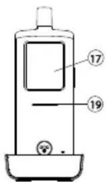
text_image
17 19natural_image
Technical line drawing of a mechanical device with internal components and airflow indicators (no text or symbols)ZUR SPEISUNG
UND ZUM
ELEKTRISCHEN
TÜRSCHLOSS
text_image
Diagram of a mobile phone front panel with numbered labels pointing to different components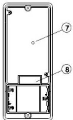
text_image
Diagram of a smartphone front panel with labeled parts 7 and 8, showing internal components and connectors.Außeneinheit
text_image
Labeled diagram of a mobile phone with numbered parts for identification and usage reference.Handgerät
text_image
18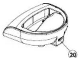
natural_image
Technical line drawing of a mechanical component with no visible text or symbolsLadeschale
natural_image
Simple icon with a black square containing the letter 'B' and a green Wi-Fi symbol inside a white rectangle (no text or labels)ALARMMODUS
natural_image
Simple black-and-white icon of a camera with plus signs, no text or symbols presentTRIGGER TIME
natural_image
Simple icon of a padlock with 'x' label, no text or symbols presentINTRODUCTION......45
CONSIGNES DE SÉCURITÉ....46
FONCTIONS....46
ACCESSOIRES STANDARD......47
PRISE EN MAIN 48
ALIMENTATION 48
UNITÉ EXTÉRIEURE 48
COMBINÉ 49
APPAIRAGE DU COMBINÉ ET DE L'UNITÉ EXTÉRIEURE .... 50
INSTALLATION DE L'UNITÉ EXTÉRIEURE....52
natural_image
Technical line drawing of a mobile phone casing with internal components (no text or symbols)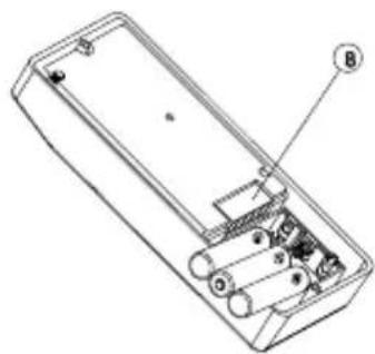
natural_image
Technical line drawing of a rectangular electronic device with internal components and labeled parts (no text or symbols)natural_image
Technical line drawing of a mechanical device with internal components and directional arrows (no text or symbols)VERS L'ALIMENTATION ET LA SERRURE DE PORTE ÉLECTRIQUE
text_image
Diagram of a mobile phone front panel with numbered labels pointing to different sections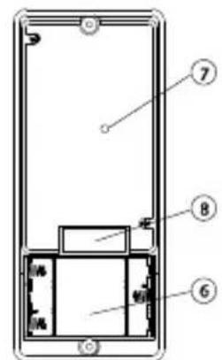
text_image
Technical diagram of a smartphone front panel with numbered components labeled 6, 7, and 8Unité extérieure
text_image
Diagram of a mobile phone with numbered parts for identification and labeling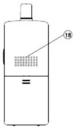
text_image
18Combiné

natural_image
Technical line drawing of a mechanical component with no visible text or symbolsChargeur
natural_image
Simple icon with a black square and green Wi-Fi signal symbol inside a white rectangle (no text or labels)MODE D'ALERTE
natural_image
Simple black icon of a battery with plus signs, no text or symbols presentnatural_image
Simple icon of a padlock with 'x' label, no text or symbols presentAlimentation : Pile Lithium rechargeable
1100mAh
3.7V
Chargeur : 6V 500mA
Dimensions: 50x142x22mm
Unité extérieure
natural_image
Technical line drawing of a mechanical device with internal components and mounting holes (no text or symbols)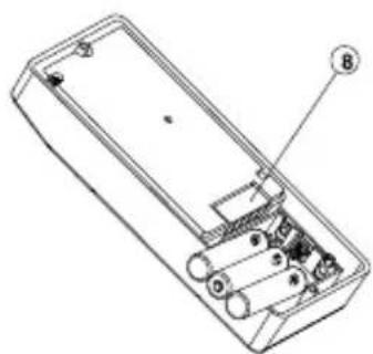
natural_image
Technical line drawing of a rectangular electronic device with internal components and labeled parts (no text or symbols)text_image
Technical line drawing of a mobile phone case with labeled components and partsnatural_image
Technical line drawing of a mechanical device with no visible text or symbolsnatural_image
Technical line drawing of a mechanical component with no visible text or symbolsCargador
natural_image
Simple icon with a black square containing the letter 'B' and a green Wi-Fi signal symbol inside a white rectangle (no text or labels)MODO DE ALARMA
natural_image
Simple black-and-white icon of a camera with plus signs, no text or symbols presentnatural_image
Simple icon of a padlock with 'x' label, no text or symbols presentnatural_image
Technical line drawing of a device casing with internal components (no text or symbols)
natural_image
Technical line drawing of a rectangular electronic device with internal components and labeled parts (no text or symbols)natural_image
Technical line drawings of a mobile phone case with labeled components (no text or symbols beyond numbers)ALLA PRESA DI CORRENTE
text_image
ALLA PRESA DI C 20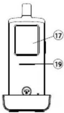
text_image
17 19ACCOPPIARE IL CORDLESS E L'UNITÀ ESTERNA
natural_image
Technical line drawing of a device with cable and mounting bracket (no text or symbols)emergenza).
natural_image
Technical line drawing of a device with internal components and directional arrows indicating motion (no text or symbols)ALL'ALIMENTATORE ED APRIPORTA ELETTRICO
text_image
Diagram of a mobile phone front panel with numbered labels pointing to different compartments or ports.
text_image
Technical diagram of a device with numbered components, likely an enclosure or panel assembly.Unità esterna

text_image
Diagram of a mobile phone with numbered parts for identification and labeling
text_image
18Cordless
natural_image
Technical line drawing of a mechanical component with no visible text or symbolsBase di carica
natural_image
Simple icon with a black square and green Wi-Fi signal wave, no text or symbols presentMODO DI ALLARME
natural_image
Simple black icon of a battery with a plus sign inside, no text or symbols presentVEILIGHEIDSWAARSCHUWINGEN 112
INTRODUCTIE....113
FUNCTIONS 113
STANDAARD ACCESSOIRES 114
AAN DE SLAG 115
VOEDING....115
BUITENUNIT 115
HANDSET 116
DE HANDSET EN DE BUITENUNIT PAREN....117
MONTAGE VAN BUITENUNIT....119
Altijd dicht....120
Altijd open 120
VEILIGHEIDSWAARSCHUWINGEN
natural_image
Technical line drawing of a device rear panel and side panel (no text or symbols)
natural_image
Technical line drawing of a rectangular electronic device with internal components and labeled parts (no text or symbols present)natural_image
Technical line drawing of a mechanical device with internal components and directional arrows (no text or symbols)NAAR VOEDING EN
ELEKTRISCH
DEURSLOT
text_image
Diagram of a mobile phone with numbered parts for identification and labeling
text_image
18Handset

natural_image
Technical line drawing of a mechanical component with no visible text or symbolsOplader
natural_image
Simple icon with a black square and green signal waves inside a white rectangle (no text or symbols)ALARMMODUS
natural_image
Simple icon of a battery with a plus sign and circuit symbols, no text or labels present.natural_image
Simple icon of a padlock with 'x' label, no text or symbols presentPROBLEEMOPLOSSINGSGIDS
Environmental Information for Customers in the European Union
European Directive 2002/96/EC requires that the equipment bearing this symbol on the product and/or its packaging must not be disposed of with unsorted municipal waste. The symbol indicates that this product should be disposed of separately from regular household waste streams. It is your responsibility to dispose of this and other electric and electronic equipment via designated collection facilities appointed by the government or local authorities. Correct disposal and recycling will help prevent potential negative consequences to the environment and human health. For more detailed information about the disposal of your old equipment, please contact your local authorities, waste disposal service, or the shop where you purchased the product.
COPYRIGHTS
Marmitek is a trademark of Pattitude B.V.
DoorPhone 170 ^™ is a trademark of Marmitek B.V. All rights reserved.
Every effort has been made to ensure that the information in this manual is accurate. Marmitek is not responsible for printing or clerical errors.
Copyright and all other proprietary rights in the content (including but not limited to model numbers, software, audio, video, text and photographs) rests with Marmitek B.V. Any use of the Content, but without limitation, distribution, reproduction, modification, display or transmission without the prior written consent of Marmitek is strictly prohibited. All copyright and other proprietary notices shall be retained on all reproductions.
Other company and product names mentioned herein may be trademarks of their respective companies. Mention of third-party products is for informational purposes only and constitutes neither an endorsement nor a recommendation. Marmitek assumes no responsibility with regard to the performance or use of these products.
DECLARATION OF CONFORMITY
Hereby, Marmitek BV, declares that this DOORPHONE 170 is in compliance with the essential requirements and other relevant provisions of the following Directives:
Directive 1999/5/EC of the European Parliament and of the Council of 9 March 1999 on radio equipment and telecommunications terminal equipment and the mutual recognition of their conformity
Directive 2004/108/EC of the European Parliament and of the Council of 15 December 2004 on the approximation of the laws of the Member States relating to electromagnetic compatibility
Directive 2006/95/EC of the European Parliament and of the Council of 12 December 2006 on the harmonisation of the laws of Member States relating to electrical equipment designed for use within certain voltage limits
Directive 2011/65/eu of the european parliament and of the council of 8 June 2011 on the restriction of the use of certain hazardous substances in electrical and electronic equipment
Commission Regulation (EC) No 278/2009 of 6 April 2009 implementing Directive 2005/32/EC of the European Parliament and of the Council with regard to ecodesign requirements for no-load condition electric power consumption and average active efficiency of external power supplies