DoorPhone 210 - Intercom MARMITEK - Free user manual and instructions
Find the device manual for free DoorPhone 210 MARMITEK in PDF.
Frequently Asked Questions - DoorPhone 210 MARMITEK
User questions about DoorPhone 210 MARMITEK
0 question about this device. Answer the ones you know or ask your own.
Ask a new question about this device
Download the instructions for your Intercom in PDF format for free! Find your manual DoorPhone 210 - MARMITEK and take your electronic device back in hand. On this page are published all the documents necessary for the use of your device. DoorPhone 210 by MARMITEK.
USER MANUAL DoorPhone 210 MARMITEK
natural_image
Black MARMITEK smartphone camera with dial and bell icon (no text or symbols on body)USER MANUAL 3
- Do not expose the components of your system to extremely high temperatures or bright light sources.
- Improper use, self-installed modifications or repairs will void any and all warranties. Marmitek does not accept any product responsibility for incorrect use of the product or use other than for which the product is intended. Marmitek does not accept liability for any consequential damage other than the legal product responsibility.
- This product is not a toy. Keep out of reach of children.
- Do not open the product (battery panel is an exception): the device may contain live parts. The product should only be repaired or serviced by a qualified expert.
- Keep batteries out of the reach of children. Dispose of batteries as chemical waste. Never use old and new batteries or different types of batteries together. Remove the batteries when you are not using the system for a longer period of time. Check the polarity (+/-) of the batteries when inserting them in the product. Wrong positioning can cause an explosion.
- Only connect the adapter to the mains after checking whether the mains voltage is the same as the values on the identification tags. Never connect an adapter or power cord when it is damaged. In that case, contact your supplier.
- Disconnect the AC/DC power adapter from the mains when this device is not in use for prolonged time.
TABLE OF CONTENTS
SAFETY WARNINGS 3
TABLE OF CONTENTS......4
INTRODUCTION 5
FEATURES....5
SET CONTENTS 5
CONTROLS LAYOUT......6
GETTING STARTED 7
Power Supply....7
Door unit 7
Backup 7
Handset 8
Pairing the handset and the door unit 9
Mounting of door Unit....10
Always close....10
Always open 10
Auxiliary terminal 11
OPERATION....11
ON / OFF 11
CALLER SETTING 12
GATE 12
VOLUME 12
BRIGHTNESS....12
CONTRAST 12
GATE LIGHT 13
ALARM MODE 13
DOOR LOCK OPEN 13
TRIGGER TIME 13
DATE/TIME 13
EXIT 14
MISSED CALL(S)....17
PRECAUTION....17
FREQUENTLY ASKED QUESTIONS....18
TECHNICAL DATA....19
COPYRIGHTS 20
INTRODUCTION
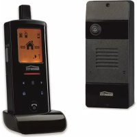
Congratulations on your purchase of the Marmitek Video DoorPhone 210. Your Video DoorPhone 210 has been manufactured and checked under the strictest possible quality control to ensure that each Video DoorPhone 210 leaves the factory in perfect condition. In the unlikely event you find any defect or experience any problem, please contact our service centre or dealer, do not attempt to repair by yourself.
Please read this manual carefully to obtain optimum performance and extended service life from the system.
FEATURES
- Mobile wireless video doorphone system.
- Always see who's at the door before you open it, from anywhere in your home.
- Get a good view of people day and night, with a digitally adjustable camera angle, zoom feature and LED lighting.
- Interference-free coverage, anywhere in your home.
- Easy installation, using existing wiring.
- Including missed call notification and automatic image storage of last 10 visitors.
• Rugged, weatherproof housing. - Open the door remotely by electric door opener (optional).
- Selectable doorbell warning: audio, visual and/or vibrate.
• Digital transmission - ensures interference-free calls.
SET CONTENTS
a. Handset
b. Door Unit
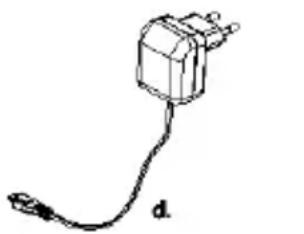
c. Charger stand
d. Switching power supply for charger stand
e. Rechargeable battery pack (installed in handset)
f. Tool
g. Screws and rivets
h. Manual
a.
b.

C.
natural_image
Simple line drawing of a plug with a cable, labeled 'd' (no text or symbols on the plug itself)
f.

e.

9.
h.
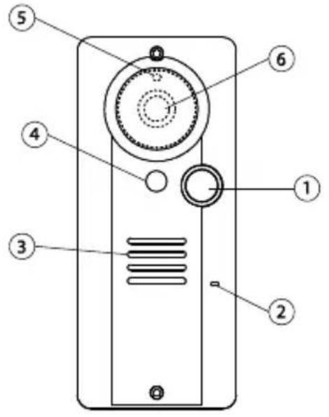
CONTROLS LAYOUT
text_image
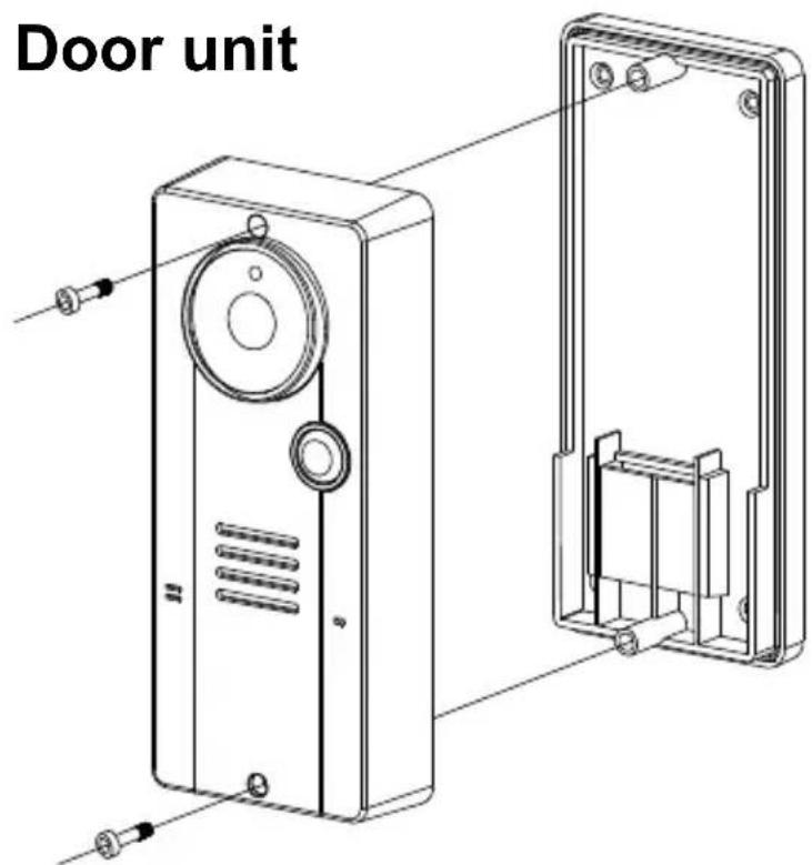
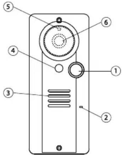
Diagram of a device with numbered parts labeled 1 through 6, showing internal components and connections.Door unit
text_image
Technical diagram of a smartphone front panel with labeled components and internal mechanisms
text_image
Technical diagram of a mechanical component with numbered parts labeled 20 and 21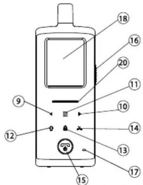
text_image
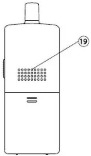
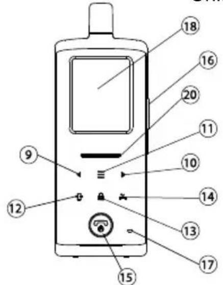
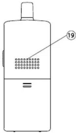
Diagram of a mobile phone with numbered parts for identification and labelingHandset unit
text_image
19
natural_image
Technical line drawing of a mechanical component with no visible text or symbolsCharging stand
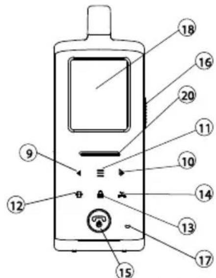
- Call button
- Microphone
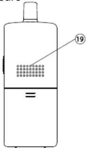
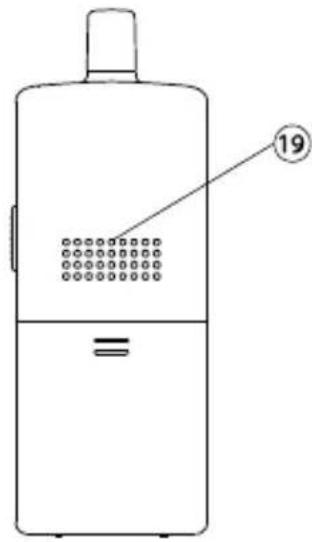
- Speaker
- White illumination LED
- Light sensor
- Camera lens
- Pairing button
- Terminal block
- Volume down/Left key
- Volume up/Right key
-
Menu key
-
Image shift key
- Door lock open key
- Missed calls key
- Hang up and power ON/OFF button
- Talk and answer button
- Microphone
- TFT screen
- Speaker
- Power and battery low indicator
- USB port
GETTING STARTED
Power Supply
text_image
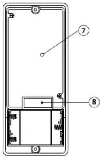
Door unit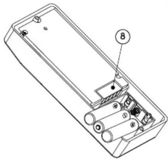
text_image
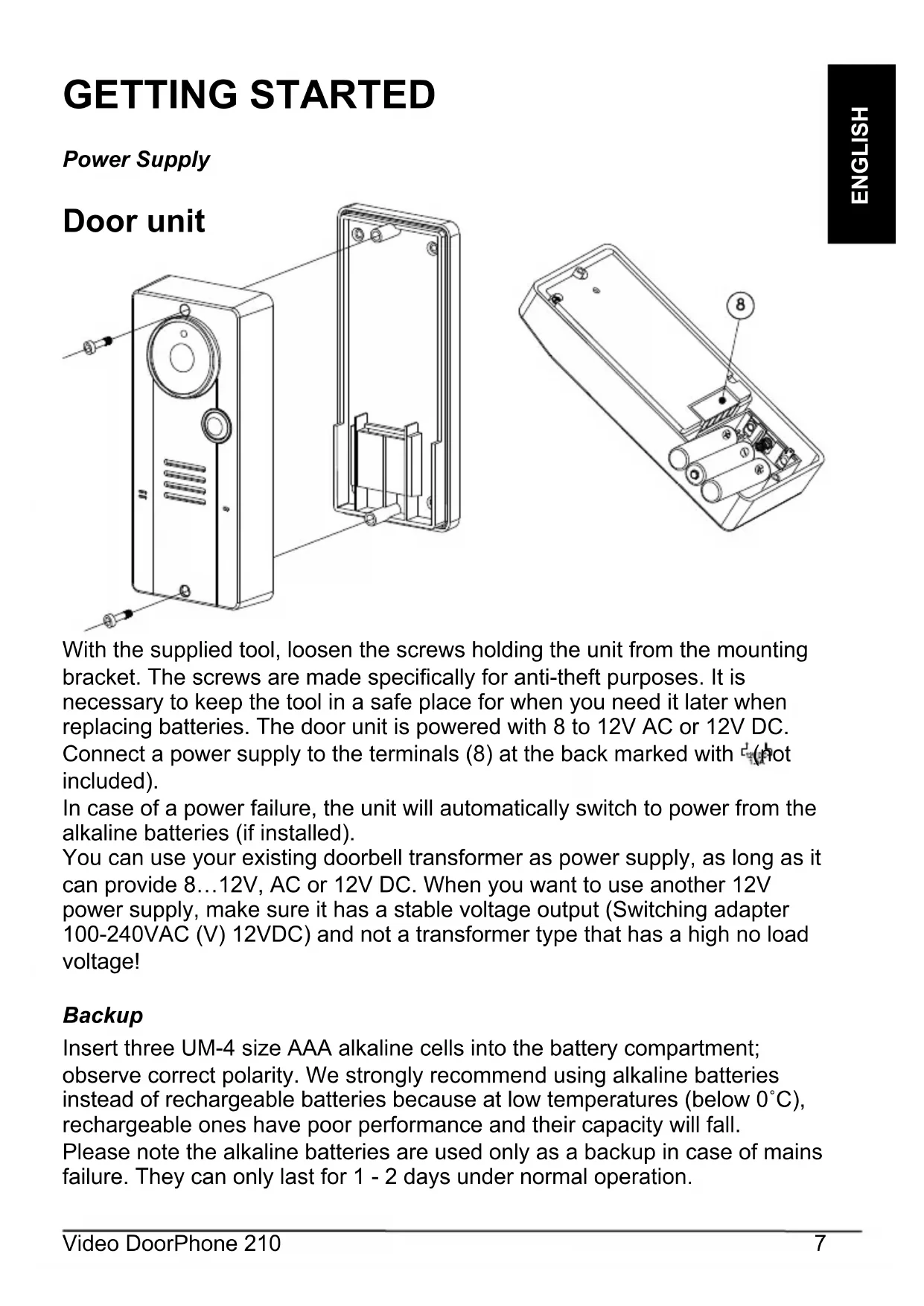
Technical diagram of an electronic device showing internal components with labeled parts 8 and numbered marker 8With the supplied tool, loosen the screws holding the unit from the mounting bracket. The screws are made specifically for anti-theft purposes. It is necessary to keep the tool in a safe place for when you need it later when replacing batteries. The door unit is powered with 8 to 12V AC or 12V DC. Connect a power supply to the terminals (8) at the back marked with (not included).
In case of a power failure, the unit will automatically switch to power from the alkaline batteries (if installed).
You can use your existing doorbell transformer as power supply, as long as it can provide 8...12V, AC or 12V DC. When you want to use another 12V power supply, make sure it has a stable voltage output (Switching adapter 100-240VAC (V) 12VDC) and not a transformer type that has a high no load voltage!
Backup
Insert three UM-4 size AAA alkaline cells into the battery compartment; observe correct polarity. We strongly recommend using alkaline batteries instead of rechargeable batteries because at low temperatures (below 0°C), rechargeable ones have poor performance and their capacity will fall. Please note the alkaline batteries are used only as a backup in case of mains failure. They can only last for 1 - 2 days under normal operation.
Handset
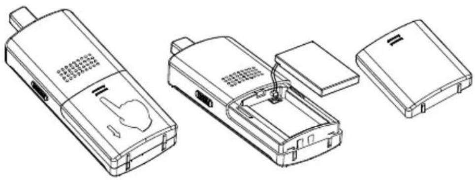
The supplied Li polymer battery pack is already installed in the handset. (To replace the battery, press down and slide open the battery door in the direction as shown, take out the battery pack and disconnect it from the socket.
natural_image
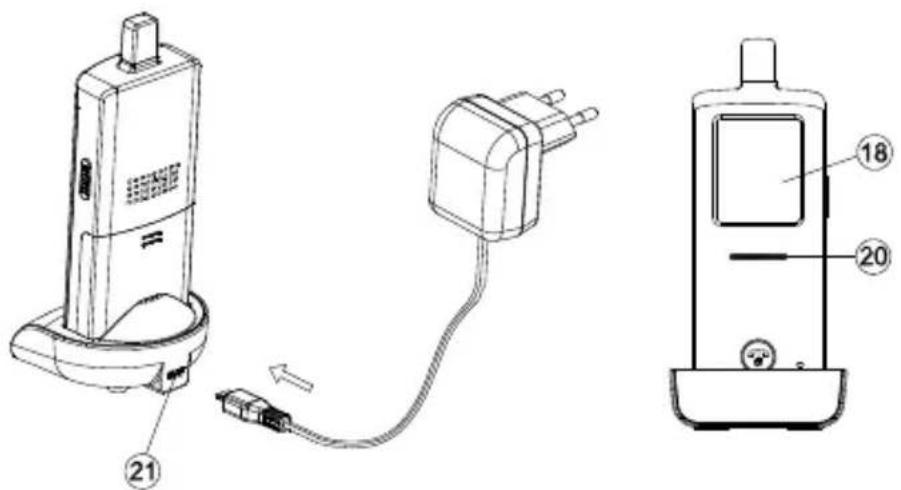
Line drawings of three electronic devices with internal components, no text or symbols presentWith the handset remaining switched off, place it onto the charger stand.
Plug in the supplied AC switching power supply into an AC outlet and connect its output plug to the USB port (21) located at the back of the charger stand.
text_image
Technical diagram showing three connected devices with numbered labels, likely illustrating a medical or electronic device assembly.The power indicator (20)
should light up red during the charging process. Adjust the position of the handset in the charger stand in case this indicator does not light up. During charging, in case the screen (18) is turned on, the segments within the battery icon will flash in turn.
The battery pack should be fully charged within 4 hours when used for the first time. The power indicator (20) will now go off (if the handset is switched off) or turn steady blue (if the handset is switched on).
Now the unit can be switched on and is ready for operation. Either taking out the unit or keeping it placed in the charger stand will cause no damage to the battery. In the latter case, when the battery is being consumed and voltage falls to a certain level, the charger stand will automatically charge up the battery.
CAUTION: BE SURE THE BATTERY IN THE HANDSET IS A RECHARGEABLE TYPE BEFORE YOU PLACE IT IN THE CHARGER STAND, OTHERWISE AN EXPLOSION MAY RESULT.
Pairing the handset and the door unit
This process is to match the door unit with the handset so that they can communicate with each other and so that no other devices (even a doorphone of an identical model) can interfere with your set.
The door unit and handset are already paired when they are shipped from the factory. However, in case interference still exists, perform pairing again to achieve better privacy and to avoid false triggering of the door lock from a
nearby doorphone system.
Place the door unit and handset close to each other within a distance of 1m.
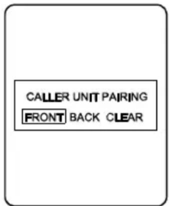
Press and hold the talk/answer button (16), then long press the power ON/OFF button (15) to switch on the unit. The screen (18) will show the following:
Use the left/right key◀(9)(10) to select either "FRONT" (represent front gate), "BACK" (represent back gate) or "CLEAR", then touch the menu key ≡ (11) to confirm. The power indicator (20) should now flash rapidly, showing the handset has entered pairing mode.
In case “CLEAR” is selected, all the originally paired door units will be cleared and you will then need to perform pairing again.
Now install alkaline batteries or connect 12V DC to the door unit. (If the door unit was already on, do a powercycle.) Then short press the pairing button (7) located at the back.
WARNING: The pairing button (7) must be pressed within 30 sec once you supply power to the door unit, otherwise pairing will not be successful.
Once the handset and the door unit are successfully paired, the image captured by the camera lens (6) will be shown in the screen (18) of the handset. The doorphone is now ready for operation. If the pairing process is not successful (the screen (18) remains blue), repeat the procedures from step 2 again. Remember when you add a second door unit to the system (for back gate use), it is necessary to perform the pairing process and select "BACK". The original front gate unit does not need to be paired again.
text_image
CALLER UNIT PAIRING FRONT BACK CLEAR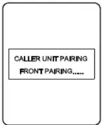
text_image
CALLER UNIT PAIRING FRONT PAIRING......
text_image
ALL PAIRING CLEARED DO PAIRING AGAINMounting of door Unit
text_image
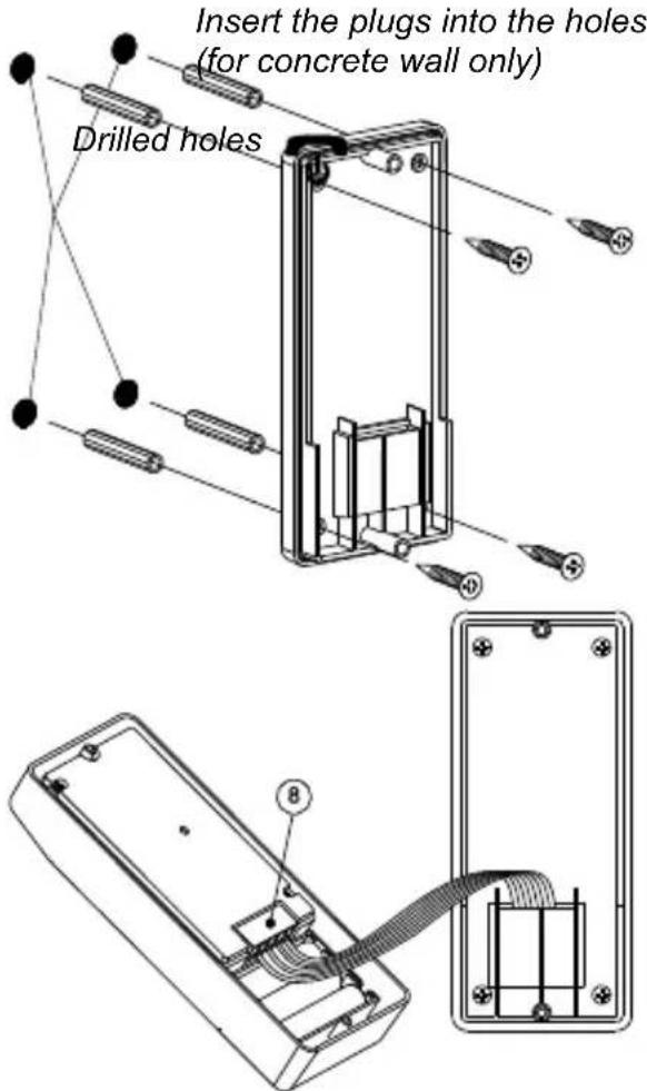
Insert the plugs into the holes (for concrete wall only) Drilled holesSelect a location near your door entrance where the surface is not too rough. We recommend that you do some polishing to get a plane surface or otherwise the unit may not be able to mount properly.
It should be noted that the mounting bracket is not installed on metal screening surfaces nor in the vicinity of other electronic devices that may reduce the operating range. Using the supplied self tap screws, fix the mounting bracket onto the wall.
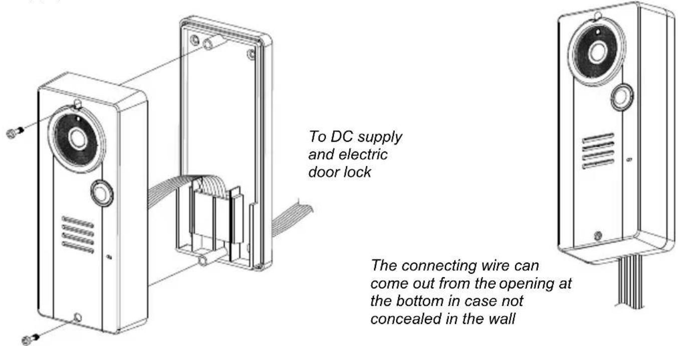
Connect the terminals marked of the 12V DC power supply at the back of the door unit. In addition, there are also terminals marked and for connecting to an electric door latch which can be remotely opened by the handset. When the DC power supply is connected, the call button (1) will be illuminated. The electric door latch opening feature will not operate when using the backup alkaline
batteries so as to keep long battery life.
CAUTION: When using the DC supply, in case the electric door latch does not function, reverse the polarity it is connected to and try again. (The two most common types of electric door latch on the market are either “always close” or “always open”).
Always close
These two terminals normally provide a 12V supply. During communication, once the door lock opening button 🔒(13) is pressed, this voltage will drop to 0V temporarily for duration of time as specified by the TRIGGER TIME function.
Always open
These two terminals normally provide 0V. During communication, once the door lock opening button 🔒 (13) is pressed, the terminals will provide a 12V supply temporarily for duration of time as specified by the 🔒 TRIGGER TIME function.
Under no circumstances should AC mains Voltage be directly connected to the terminal blocks (8)!
Auxiliary terminal
These two terminals act like a switch and will be short circuited as long as the doorbell button (1) is pressed, however, there is no voltage supply from these terminals. They can be used to trigger a conventional door chime or a courtesy light at the entrance.
Now insert the 3 pcs AAA (UM-4) alkaline batteries into the battery compartment as this can serve as a battery back-up in case the 12V DC supply fails.
text_image
To DC supply and electric door lock The connecting wire can come out from the opening at the bottom in case not concealed in the wallInstall the back of the door unit onto the mounting bracket using the supplied tool.
The door unit is housed in a high impact ABS/PC cabinet, which can achieve the professional grade ruggedness required in most outdoor applications. Rubber gaskets seal around all of the joints keep out dust, rain, snow and spray, assuring years of reliable operation even in harsh environments. The unit meets to IP-54 standard and can operate from -20°C to 50°C.
OPERATION
ON / OFF
Switch on the handset by a long press (over 3 seconds) of the Power ON/OFF button 📞15). (Long press the same button again in case you want to switch off the unit.)
The power indicator (20) will light up blue. In case the Li battery has run down, the power indicator will start flashing blue. At the same time, the battery icon shown on screen (18) will become empty and flashing. Place the unit into the charger stand to charge up the battery.
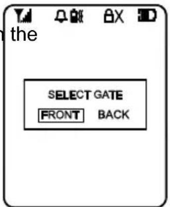
During standby mode, a short press of the Talk/answer button 📋/ (16) will initiate communication with door unit and wake up the screen (18) showing the view as captured by the lens (6) (In case a backgate caller unit has been installed, the screen (18) will prompt you to select “FRONT” or “BACK”. Use the left/right key◀(9) (10) to select and menu key (11) to confirm.).
Long touch the menu key ≈11) for over 2 sec to show the menu on the screen (18): Use the left/right key◀(9) (10) to select the parameters to be set, then short touch the menu key ≡(11) to confirm. The selectable values now show yellow while the parameter description resumes the light blue colour.
CALLER SETTING
GATE
This will select the door unit you prefer to change the settings for. Use the left/right key (9) (10) to select between FRONT or BACK gate, then short touch the menu key (1) to confirm your setting.
VOLUME
This will set the speaker volume of the door unit. Use the left/right key◀(9) (10) to select between the 5 levels with 1 being the lowest and 5 being the highest volume. Short touch the menu key ≡ (11) to confirm your setting.
BRIGHTNESS
This will set the brightness of the visitor's image as shown on the screen (18). Use the left/right key (9) (10) to select between the 5 levels with 1 being the lowest and 5 being the highest brightness. Short touch the menu key ≡ (11) to confirm your setting.
CONTRAST
This will set the contrast of the visitor's image as shown on the screen (18). Use the left/right key (9) (10) to select between the 5 levels with 1 being the lowest and 5 being the highest contrast. Short touch the menu key (11) to confirm your setting.
text_image
the SELECT GATE FRONT BACK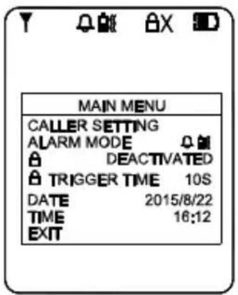
text_image
MAIN MENU CALLER SETTING ALARM MODE DEACTIVATED TRIGGER TIME 10S DATE 2015/8/22 TIME 16:12 EXIT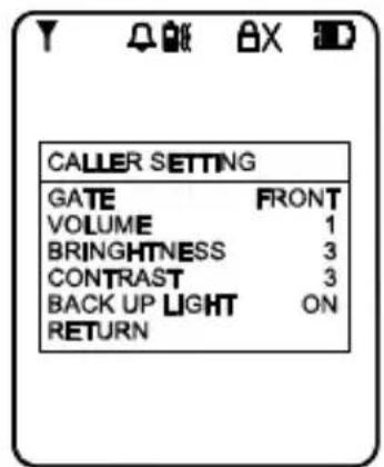
text_image
CALLER SETTING GATE FRONT VOLUME 1 BRINGHTNESS 3 CONTRAST 3 BACK UP LIGHT ON RETURNGATE LIGHT
For the door unit installed at a location where there is not enough illumination even at day time, this function can be used to switch on the white LED every time the call button (1) is being pressed which serves as a back-up light to illuminate the face of your visitor.
Use the left/right key (9) (10) to select between ON, OFF or AUTO. Short touch the menu key ≡(11) to confirm.
ON: gate light always on once the call button (1) is pressed.
OFF: gate light always off.
AUTO: gate light will go on, once the call button (1) is pressed and when the light sensor (5) detects a low light intensity.
After completing the settings, select RETURN to go back to the main menu.
ALARM MODE
This will set the method of alert when a visitor calls, either with a ding-dong sound or vibration or both. Use the left/right key (9) (10) to select between
(ding-dong sound and vibration) or (ding-dong sound only) or (vibration only). Short touch the menu key ≡(11) to confirm.
The corresponding icon will be shown on the top of the screen (18). In case blank is selected, no ding-dong sound and vibration alert will be provided; only the visitor's image will be shown on the screen (18) when someone calls.
DOOR LOCK OPEN
This is to activate or deactivate the door lock open key (13). Use the left/right key (9) (10) to select between "ACTIVATE" or "DEACTIVATE", Short touch the menu key (11) to confirm. In case DEACTIVATE is selected, the icon will show up at the top part of the screen (18).
TRIGGER TIME
This is the duration time for how long the door lock is being triggered. Use the left/right key (9) (10) to select between 2, 5, 10, 20 or 25 seconds. Short touch the menu key (11) to confirm.
DATE/TIME
This will set the internal clock. Use the left/right key (9) (10) to set the year/month/date as well as the hour/minute, touch the menu key (1) to confirm your setting. In case the Li battery has totally run down, the internal clock will stop and it is necessary to set the time again after the battery is charged up.
EXIT
Select this parameter to exit from the menu, short touch the menu key (11) to confirm. Alternatively, in case no key is being touched within a period of 10 sec, the menu will exit from the screen (18) automatically.
To return to standby mode and switch off the screen (18), short press the power/hang up button (15). Alternatively, if no key is being touched for over 1 min, the handset will return to standby mode automatically.
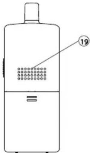
During conversation and when the menu is not shown on the screen (18), the sound volume heard through the speaker (19) can also be adjusted using the left/right key ◀▶(9) (10) and the corresponding volume bar graph is shown on the screen (18). Please note the loudness of the door chime is fixed and cannot be adjusted.
Make sure there is power supplied to the caller unit (by either 12V DC or alkaline batteries). Now press the Call button (1), a ding-dong tone will be heard. Until a handset answers the call, the ding-dong tone will be heard periodically, reminding the visitor to keep waiting. In case there is no answer after 30 seconds, the caller unit ends the call by itself. Press the Call button (1) to initiate the call again.
N.B. In case there are two caller units (frontgate and backgate), only the unit whose call button ⏻(1) is first pressed will send out a call signal to handset, the remaining unit will be kept in standby mode until the conversation is over. If its call button ⏻(1) is pressed during this period, a two “Be-Be” sound will be heard, indicating the unit is under hold mode.
Once the call is being answered, the ding-dong tone stops ringing.
Conversation can now be conducted by speaking into the microphone (2).
Upon receiving a call, the screen (18) will show the image of the visitor, but audio communication with the visitor will not be initiated unless the call is answered by a short press of the Talk/answer button Ⓣ(16).
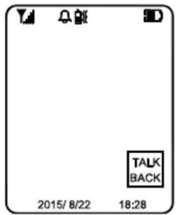
Once the Talk/answer button 📋(16) is pressed, conversation is now possible and the voice of the visitor can be heard from the speaker (19). To talk back to the visitor, press and hold the Talk/answer button 📋(16) and speak towards the microphone (17) once you
text_image
TALK BACK 2015/ 8/22 18:28see the text “TALK BACK” appear at the lower right corner of the screen (18) (If you speak before seeing the text, then it is possible that the visitor may NOT be able to hear some of your first spoken words.).
Release the Talk/answer button 📋 (16) after you finished speaking to listen to the visitor. It should be worth noted that the voice of the visitor cannot be heard while pressing the Talk/answer button 📋 / (16). Upon
finishing the conversation, short press the Power/hang up button (15) to end the call.
In case you need to get a more magnified image of the visitor, short touch the menu key ≡(11), then short touch either the left/right key (9)×(10) to achieve a 2x zoom image on the screen (18).
Besides, to get a wider scope of view at the door entrance, you can use the image shift function. Short touch the image shift key (12), then use the left/right key (9) (10) to shift the image on the screen (18).
This system has an automatic end call feature. In case the resident does not talk back to the visitor (i.e. press the Talk/answer button 📋/√ (16)) for over 60 sec, the call will be ended automatically. Such a feature is useful to protect your privacy in case you forget to end the call by pressing the
Power/hang up button (15).
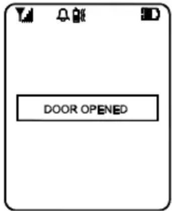
Once a call has been answered, you can use the door lock open key (13) to remotely open the electric door latch for the visitor (this function is only available if there is 12V DC supply to the caller unit and your door is equipped with an electric latch). Long touch the door lock open key (13) for over 3 sec and the text "DOOR OPENED" appears on the screen (18', showing the door latch is opened. The text will disappear after 3 sec.)
text_image
DOOR OPENEDUnder standby mode (i.e. when no call is set up between handset and caller unit), the electric door latch can also be opened by a short press of the
Talk/answer button Ⓥ/ (16), and then a long touch of the door lock open
key (13) for over 3 sec.
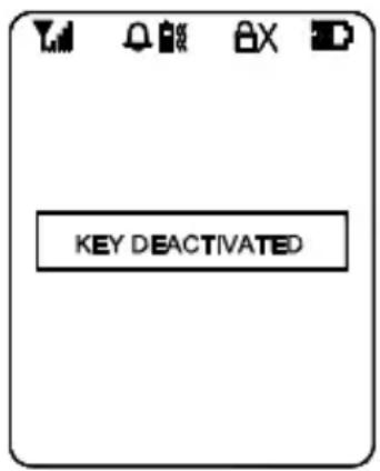
To avoid misuse by children, this door lock opening function can be activated or deactivated. When deactivated, touching the key (13) will have no effect and the text "KEY DEACTIVATED" will show on the screen (18) for 2-3 sec.
text_image
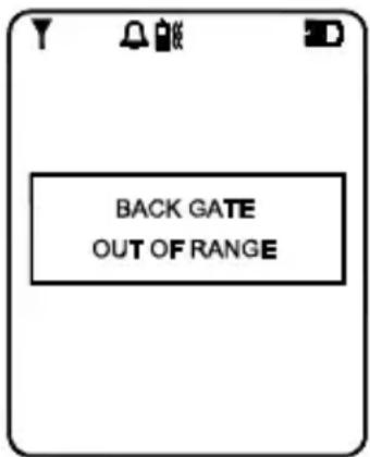
KEY DEACTIVATEDWhenever the handset is located at a spot which is outside the communication range of the caller unit (either front or back gate or both), an alarm will be heard and the screen (18) will show the following:
Such alarm cannot be immediate and will alert you only when you are out of range for over 2 minutes (when 12V DC supply is available or 20 minutes if a battery is used). Once the handset falls back in range, the alarm will stop automatically. A short press of the power/hang up button (15) can cut off the alarm sound but the
text_image
BACK GATE OUT OF RANGE“out of range” text will continue flashing on the screen (18) until the handset falls within the range of the caller unit.
N.B. This out of range alert will also occur in case the batteries of the caller unit run down and its DC power is cut off.
When the Light sensor (5) detects a low light intensity, once the call button ⏻(1) is pressed, the white illumination LED (4) will light up automatically to illuminate the face of the visitor. This is subjected to “AUTO” being selected for the GATE LIGHT function menu.
A beep sound will be heard whenever a key is being touched to validate your entry. To eliminate such a beep sound, long touch the left key ◀(9) until a second beep is heard. To resume the beep sound, long touch the right ▶ (10) key until a beep sound is heard.
MISSED CALL(S)
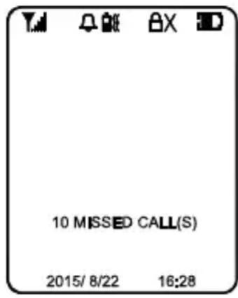
Under the circumstances of an unanswered call from a visitor (e.g. you are away from home), the missed call indicator will start flashing in standby mode. At the same time, the text "X MISSED CALL(S)" will be shown at the bottom part of the screen (18) whenever it is woken up (X represents the total number of missed calls, the maximum number of missed calls that can be stored is 10, with the most updated entry overriding the oldest entry).
text_image
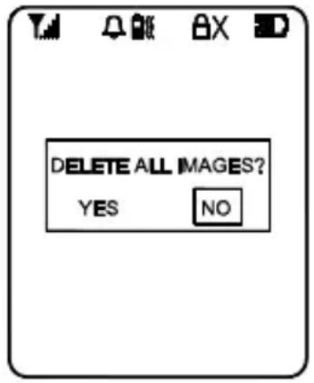
10 MISSED CALL(S) 2015/ 8/22 16:28Short press the Talk/answer button (16) to initiate the screen (18). Short touch the missed calls key (14) to show the 1st image, touch again will show the subsequent images until after the last recorded image, the screen (18) will prompt you if you prefer to delete the images, use the left/right key (9) (10) to select and the menu key (11) to confirm. In case NO is selected, the missed calls indicator will continue to flash until all stored images are deleted.
text_image
DELETE ALL IMAGES? YES NOPRECAUTION
- Use only the supplied AC switching power supply for charging the handset. Use of another supply may cause damage to the handset.
- Do not mix old and new alkaline batteries in the door unit.
- When not using the Video DoorPhone 210 for a long period of time, remove all batteries from the handset and the door unit to avoid battery leakage.
- Do not leave the handset exposed to strong sunlight for a long period of time or near any heat source, moisture and an excessive dusty environment.
- Do not open the cabinet; no serviceable parts are inside.
- When using for the first time, switch off the handset and charge up the supplied battery pack for 4 – 5 hours using the charger stand.
FREQUENTLY ASKED QUESTIONS
The handset and door unit cannot communicate
- The handset and door unit have a different ID code, perform the pairing process
- The battery has run down. Replace the batteries in the door unit or recharge the battery in the handset using the charger stand.
The communication distance becomes short
- There are many steel structures between the handset and the door unit. Relocate the position of the handset.
- Battery has run down. Replace the batteries in the door unit or recharge the battery in the handset using the charger stand.
Out-of-range alert always on
No power supply to the door unit. Replace the batteries or check the DC supply to the door unit.
Always showing low battery on the handset
The battery pack is damaged and cannot be recharged. Replace with new battery pack.
The door latch cannot be remotely opened by handset
- The door lock opening button (13) is deactivated. Activate the door lock opening button (13).
- No DC supply to the door unit. Check if DC supply is available.
- Wrong connection at terminal block. Make proper connection.
New door unit (backgate) cannot communicate with indoor unit
The new unit is not properly paired to existing unit. Perform pairing process.
The Touch keys have no response
Disconnect the battery from the socket to reset the handset and re-connect again.
Do you have other questions that have not been resolved by the above information?
Please go to www.marmitek.com
TECHNICAL DATA
Handset
Power Rechargeable Li battery pack
800mAh
3.7V
Charger 5V 600mA
Power consumption Stand-by 78mA
Active Transmission mode 190mA
Reception mode 410mA max
Doorbell Selectable audio, visual or vibration alert
Dimensions 50x142x22mm
Door unit
Range Up to 300m in free field, up to 30m through walls
and ceilings.
Backup Power Battery (3x AAA alkaline, for 3 days backup, not
included)
Power adapter 8...12 V DC or AC, min. 500mA without door
opener, 1000mA with door opener (not included)
Frequency 863-870Mhz
Power consumption Stand-by 85mA
Active
Transmission mode 200n
Reception mode 450mA
Material ABS / PC / PMMA
Connection External power
12V AC or D
Make connection 12V, 1A MAX
Break
connection 12V, 1A MAX
AUX connector MAX load, 12V/200mA
Ambient temperature - 20°C to + 50°C
IP value IP54
Camera 1/4" CMOS with 300K pixel
Dimensions 57x139x30mm
In order to continue improving the product, Marmitek reserves the right to change specifications and/or designs without prior notice.

Environmental Information for Customers in the European Union
European Directive 2002/96/EC requires that the equipment bearing this symbol on the product and/or its packaging must not be disposed of with unsorted municipal waste. The symbol indicates that this product should be disposed of separately from regular household waste streams. It is your responsibility to dispose of this and other electric and electronic equipment via designated collection facilities appointed by the government or local authorities.
Correct disposal and recycling will help prevent potential negative consequences to the environment and human health. For more detailed information about the disposal of your old equipment, please contact your local authorities, waste disposal service, or the shop where you purchased the product.
COPYRIGHTS
Marmitek is a trademark of Pattitude B.V.
xxxx™ is a trademark of Marmitek B.V. All rights reserved. Every effort has been made to ensure that the information in this manual is accurate. Marmitek is not responsible for printing or clerical errors. Copyright and all other proprietary rights in the content (including but not limited to model numbers, software, audio, video, text and photographs) rests with Marmitek B.V. Any use of the Content, but without limitation, distribution, reproduction, modification, display or transmission without the prior written consent of Marmitek is strictly prohibited. All copyright and other proprietary notices shall be retained on all reproductions. Other company and product names mentioned herein may be trademarks of their respective companies. Mention of third-party products is for informational purposes only and constitutes neither an endorsement nor a recommendation. Marmitek assumes no responsibility with regard to the performance or use of these products.
MARMITEK BV - P.O. BOX 4257 - 5604 EG EINDHOVEN THE NETHERLANDS
SICHERHEITSHINWEISE
natural_image
Technical line drawing of a device housing with internal components and mounting points (no text or symbols)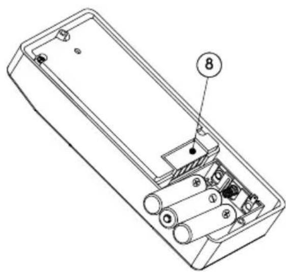
natural_image
Technical line drawing of an internal battery housing with labeled components (no text or symbols beyond numbered label)natural_image
Line drawings of three different mobile phone modules with internal components (no text or symbols)natural_image
Technical line drawing of a handheld device with attached plug and cable, labeled with number 21 (no text or symbols beyond labels)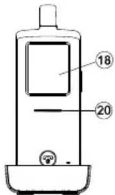
text_image
18 20text_image
DELETE ALL IMAGES? YES NOtext_image
Diagram of a device with numbered parts labeled 1 through 6, showing internal components and connections.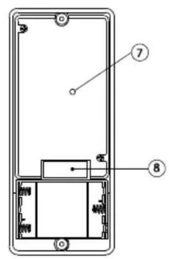
text_image
Technical diagram of a device with labeled components, showing internal structure and numbered parts 7 and 8.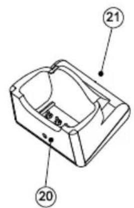
text_image
Technical diagram of a mechanical component with numbered parts labeled 20 and 21Unité extérieure
text_image
Diagram of a mobile phone with numbered parts for identification and labelingCombiné
text_image
19
natural_image
Technical line drawing of a mechanical component with no visible text or symbolsBase de charge
natural_image
Technical line drawing of an open battery casing with internal components and labeled parts (no text or symbols beyond numbered annotations)natural_image
Line drawings of three electronic devices with internal components, no text or symbols presentnatural_image
Technical line drawing of a handheld device with attached plug and cable (no text or symbols)
text_image
18 20text_image
DELETE ALL IMAGES? YES NOPRÉCAUTIONS
text_image
Diagram of a remote control device with numbered parts labeled 1 through 6
text_image
Technical diagram of a mobile phone front panel with labeled components 7 and 8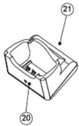
text_image
Technical diagram of a mechanical component with numbered parts labeled 20 and 21Unidad exterior
text_image
Diagram of a mobile phone with numbered parts for identification and labelingAuricular
text_image
19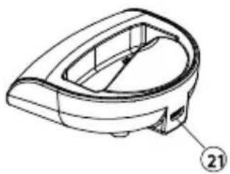
natural_image
Technical line drawing of a mechanical component with no visible text or symbolsCargador
natural_image
Line drawings of three different electronic devices with visible internal components (no text or symbols)text_image
Technical diagram showing three electronic devices with labeled parts: a mobile phone, a plug-in socket, and a handheld device.text_image
DELETE ALL IMAGES? YES NOMaterial ABS / PC / PMMA
text_image
Diagram of a device with numbered parts labeled 1 through 6, showing internal components and connections.
text_image
Technical diagram of a smartphone front panel with labeled components 7 and 8
text_image
Technical diagram of a mechanical component with numbered parts labeled 20 and 21Unità esterna

text_image
Diagram of a mobile phone with numbered parts for identification and labelingCordless
text_image
19
natural_image
Technical line drawing of a mechanical component with no visible text or symbolsnatural_image
Line drawings of three different electronic devices with internal components, shown from different angles (no text or symbols present)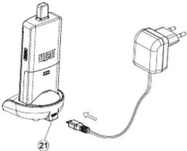
natural_image
Technical line drawing of a handheld device with attached plug and cable (no text or symbols)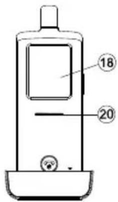
text_image
18 20ACCOPPIARE IL CORDLESS E L'UNITÀ ESTERNA
text_image
DELETE ALL IMAGES? YES NOVEILIGHEIDSWAARSCHUWINGEN
VEILIGHEIDSWAARSCHUWINGEN....101
INHOUDSOPGAVE 102
INTRODUCTIE 103
FUNCTIONS....103
INHOUD VAN SET 103
BEDIENINGSOVERZICHT 104
AAN DE SLAG....105
VOEDING....105
BUITENUNIT 105
Back-up 105
HANDSET 106
MONTAGE VAN BUITENUNIT 108
Altijd dicht 108
Altijd open....109
natural_image
Technical line drawing of two electronic components: a cable and a cylindrical tool, labeled d. and f.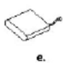

text_image
UserguideBEDIENINGSOVERZICHT
text_image
Diagram of a device with numbered parts labeled 1 through 6, showing internal components and connections.Deurunit

text_image
Technical diagram of a smartphone front panel with labeled components and internal structure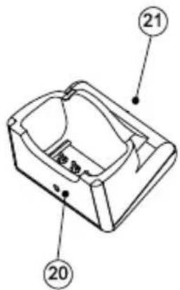
text_image
Technical diagram of a mechanical component with numbered parts labeled 20 and 21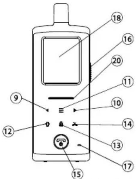
text_image
Diagram of a mobile phone with numbered parts for identification and labelingHandsetunit
text_image
19
natural_image
Technical line drawing of a mechanical component with no visible text or symbolsOplaadhouder
natural_image
Line drawings of three different mobile phone modules with internal components (no text or symbols)Plaats de nog
natural_image
Technical line drawing of a handheld device with attached plug and cable (no text or symbols)
text_image
18 20text_image
DELETE ALL IMAGES? YES NOVOORZORGSMAATREGELEN
DECLARATION OF CONFORMITY
Hereby, Marmitek BV, declares that this VIDEO DOORPHONE 210 is in compliance with the essential requirements and other relevant provisions of the following Directives:
Directive 1999/5/EC of the European Parliament and of the Council of 9 March 1999 on radio equipment and telecommunications terminal equipment and the mutual recognition of their conformity
Directive 2004/108/EC of the European Parliament and of the Council of 15 December 2004 on the approximation of the laws of the Member States relating to electromagnetic compatibility
Directive 2006/95/EC of the European Parliament and of the Council of 12 December 2006 on the harmonisation of the laws of Member States relating to electrical equipment designed for use within certain voltage limits
Directive 2011/65/eu of the european parliament and of the council of 8 June 2011 on the restriction of the use of certain hazardous substances in electrical and electronic equipment
Commission Regulation (EC) No 278/2009 of 6 April 2009 implementing Directive 2005/32/EC of the European Parliament and of the Council with regard to ecodesign requirements for no-load condition electric power consumption and average active efficiency of external power supplies