
TUFGaming650B - Phone charger ASUS - Free user manual and instructions
Find the device manual for free TUFGaming650B ASUS in PDF.
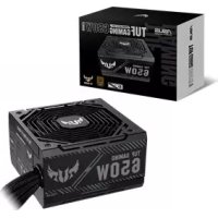



| Product type | Computer power supply |
| Brand | Asus |
| Model | TUF GAMING 650B |
| Rated power | 650 W |
| Connectors | 24-pin (ATX), 4+4-pin (CPU), 6+2-pin (PCIe), 4-pin (peripheral), SATA |
| Modular cables | Yes, included with the unit |
| Power switch | Yes, on the back |
| Fan | Built-in, do not obstruct |
| Operating temperature | 0 °C to 50 °C |
| Operating humidity | 20 % to 80 % RH |
| Maintenance and cleaning | Do not open; wipe with a dry cloth |
| Safety | Internal high voltage; do not expose to water |
| Spare parts | Modular cables only (use the ones provided) |
| Repairability | Not user repairable; opening voids warranty |
| Warranty | Void if opened |
Frequently Asked Questions - TUFGaming650B ASUS
User questions about TUFGaming650B ASUS
0 question about this device. Answer the ones you know or ask your own.
Ask a new question about this device
Download the instructions for your Phone charger in PDF format for free! Find your manual TUFGaming650B - ASUS and take your electronic device back in hand. On this page are published all the documents necessary for the use of your device. TUFGaming650B by ASUS.
USER MANUAL TUFGaming650B ASUS
TUF GAMING POWER SUPPLY UNIT
Quick Start Guide
Quick Start Guide (Traditional Chinese)
Quick Start Guide (Simplified Chinese)
Quick Start Guide (JP)
Conventions used in this guide
To ensure that you perform certain tasks properly, take note of the following symbols used throughout this manual.

DANGER/WARNING: Information to prevent injury to yourself when trying to complete a task.
NOTE: Tips and additional information to help you complete a task.
Product overview
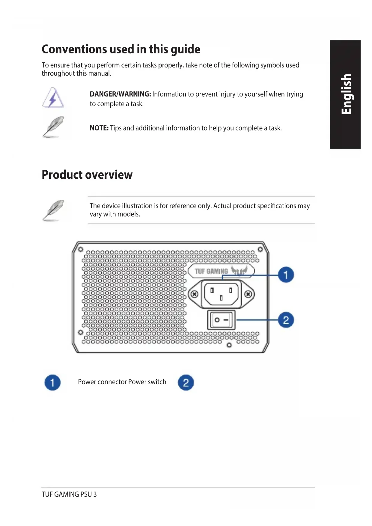
The device illustration is for reference only. Actual product specifications may vary with models.
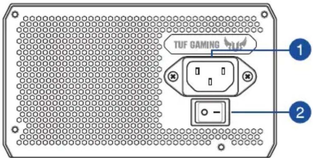
1
Power connector Power switch
2
Installing your TUF GAMING Power Supply Unit

Before installing or removing cables, ensure that the system is turned off, and all power cables for the system and all attached devices are unplugged.
- Follow the directions of your chassis manual and secure your TUF GAMING power supply unit into your chassis using the mounting screws.
- Connect the bundled cables to your TUF GAMING power supply unit.
- Connect the power connectors to your motherboard and peripheral devices according to your preference. You may refer to the list below to check which devices each power connector can be connected to.
- The power connectors may vary between different models of TUF GAMING power supply units.
- Refer to your motherboard's user manual for more information on the location and connecting the power connectors mentioned below.
- Connect the 24-pin or 20-pin Main Power Connector to the motherboard's 24-pin or 20-pin power connector.
- Connect the 4+4 pin CPU +12V Power Connector to the CPU power socket on the motherboard.
- Connect the 4-pin Peripheral Power Connector to peripheral devices if needed.
- Connect the 6+2 pin PCI-E +12V Power Connector to the PCI-E graphics card.
- Connect the SATA Power Connector to devices with a Serial ATA interface.
- Connect your TUF GAMING power supply unit to a power source using the bundled power cord.
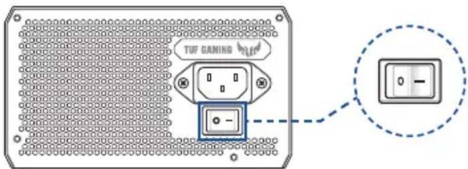
- Flip the Power Switch to the "I" position to turn on your power supply unit.
Safety information
- High voltages are present in the power supply unit, it is extremely dangerous to open the power supply case or attempt to repair/clean the power supply unit. You should NEVER, under any circumstances, open the power supply unit.
- The Warranty will become void if the cover of the power supply unit is opened; there are no serviceable components inside the power supply unit. • DO NOT insert any objects into the power supply unit.
- DO NOT place any objects in front of the fan or the ventilation area of the power supply unit that may obstruct or restrict the airflow.
- USE ONLY the modular cables bundled with the power supply unit.
- DO NOT use the power supply unit near water, or in high temperature or high humidity environments.
- The power supply unit should be operated in suitable environment. (Operating temperature: 0° to 50°C , Relative Humidity: 20% to 80% )
- The power supply unit is for integration into a computer, and not intended for external or outdoor usage.
- Failure to comply with any manufacturer instructions and any of the safety instructions will immediately void all warranties and guarantees.
Notice labels


提示符號
1
Power socket Power switch
2
Safety precautions

Power socket Power switch

Installing your TUF GAMING power supply


About this manual

Power connector Power switch

Installing the power supply unit

Safety precautions

1


1

1



Conventions used in this guide
To ensure that you perform certain tasks properly, take note of the following symbols used throughout this manual.

1



1





Power socket Power button

Installing Your TUF GAMING Power Supply Unit


Notation rules used in this manual
1
Power connector Power switch
2


1


1
Power connector Power switch
Installing Your TUF GAMING Power Supply

Before installing or removing cables, make sure that the system is turned off and that all power cables and all connected devices are unplugged.
- Follow the case instructions and secure your TUF GAMING power supply into the case using screws.
- Connect the included cables to the TUF GAMING power supply.
- Connect the power connectors for the motherboard and peripheral devices according to your preferences. You can refer to the list below to see which devices each power connector can be connected to.
- Power connectors may vary depending on the model of the TUF GAMING power supply.
- Refer to the motherboard user manual for more information and for connecting the connectors listed below.
- Connect the 24-pin or 20-pin connector, i.e., the main power connector, to the 24-pin or 20-pin motherboard connector.
- Connect the 4+4 pin CPU +12V connector to the processor power socket on the motherboard.
- Connect the 4-pin connector, i.e., the peripheral connector, to peripheral devices, if necessary.
- Connect the 6+2 pin PCI-E +12V power connector to the PCI-E graphics card.

Conventions used in this manual
To ensure proper performance of certain tasks, observe the symbols used in this manual.


Safety information

1
Power connector Power switch
2
Install your TUF GAMING power supply

Safety information

Safety information

1


1



1

- TUF GAMING POWER SUPPLY UNIT
- CONVENTIONS USED IN THIS GUIDE
- PRODUCT OVERVIEW
- INSTALLING YOUR TUF GAMING POWER SUPPLY UNIT
- SAFETY INFORMATION
- NOTICE LABELS
- 提示符號
- SAFETY PRECAUTIONS
- INSTALLING YOUR TUF GAMING POWER SUPPLY
- ABOUT THIS MANUAL
- INSTALLING THE POWER SUPPLY UNIT
- NOTATION RULES USED IN THIS MANUAL
- CONVENTIONS USED IN THIS MANUAL
- INSTALL YOUR TUF GAMING POWER SUPPLY
Brand : ASUS
Model : TUFGaming650B
Category : Phone charger