
DPP200 - Drill MAKITA - Free user manual and instructions
Find the device manual for free DPP200 MAKITA in PDF.

| Feature | Details |
|---|---|
| Product type | Gardening tool |
| Power supply | Wireless, battery |
| Battery voltage | 18 V |
| Battery capacity | Not specified |
| Weight | Not specified |
| Recommended use | Green space maintenance, hedge trimming |
| Included accessories | Not specified |
| Maintenance | Regular cleaning, battery check |
| Safety | Use protective glasses, follow safety instructions |
| Warranty | Not specified |
| Additional information | Check battery compatibility with other Makita tools |
Frequently Asked Questions - DPP200 MAKITA
User questions about DPP200 MAKITA
0 question about this device. Answer the ones you know or ask your own.
Ask a new question about this device
Download the instructions for your Drill in PDF format for free! Find your manual DPP200 - MAKITA and take your electronic device back in hand. On this page are published all the documents necessary for the use of your device. DPP200 by MAKITA.
USER MANUAL DPP200 MAKITA
| EN Cordless Hole Puncher INSTRUCTION MANUAL 6 | ||
| FR Poinçonneuse Sans Fil MANUEL D'INSTRUCTIONS 18 | ||
| DE Akku-Lochstanze BETRIEBSANLEITUNG 31 | ||
| IT Punzonatrice a batteria ISTRUZIONI PER L'USO 44 | ||
| NL Accugatenpons GEBRUIKSAANWIJZING 57 | ||
| ES Perforador Inalámbrico MANUAL DE MANUAL DE MANUAL DE MANUAL DE MANUAL DE MANUAL DE MANUAL DE MANUAL DE MANUAL DE MANUAL DE MANUAL DE MANUAL DE MANUAL DE MANUAL DE MANUAL DE MANUAL DE MANUAL DE MANUAL DE MANUAL DE MANUAL DE MANUAL DE MANUAL DE MANUAL DE MANUAL DE MANUAL DE MANUAL DE MANUAL DE MANUAL DE MANUAL DE MANUAL DE MANUAL DE MANUAL DE MANUAL DE MANUAL DE MANUAL DE MANUAL DE MANUAL DE MANUAL DE MANUAL DE MANUAL DE MANUAL DE MANUAL DE MANUAL DE MANUAL DE MANUAL DE MANUAL DE MANUAL DE MANUAL DE MANUAL DE MANUAL DE MANUAL De MANUAL De MANUAL De MANUAL De MANUAL De MANUAL De MANUAL De MANUAL De MANUAL De MANUAL De MANUAL De MANUAL De MANUAL De MANUAL De MANUAL De MANUAL De MANUAL De MANUAL De MANUAL De MANUAL De MANUAL De MANUAL De MANUAL De MANUAL De MANUAL De MANUAL De MANUAL De MANUAL De MANUAL De MANUAL De MANUAL De MANUAL De MANUAL De MANUAL De MANUAL De MANUAL De MANUAL De MANUAL De MANUAL De MANUAL De MANUAL De MANUAL De MANUAL De MANUAL De MANUAL De MANUAL De MANUAL De MANUAL De MANUAL De MANUAL De MANUAL DE MANUAL DE MANUAL DE MANUAL DE MANUAL DE MANUAL DE MANUAL DE MANUAL DE MANUAL DE MANUAL DE MANUAL DE MANUAL DE MANUAL DE MANUAL DE MANUAL DE MANUAL DE MANUAL DE MANUAL DE MANUAL DE MANUAL DE MANUAL DE MANUAL DE MANUAL DE MANUAL DE MANUAL DE MANUAL DE MANUAL DE MANUAL DE MANUAL DE MANUAL DE MANUAL DE MANUAL DE MANUAL DE MANUAL DE MANUAL DE MANUAL DE MANUAL DE MANUAL DE MANUAL DE MANUAL DE MANUAL DE MANUAL DE MANUAL DE MANUAL DE MANUAL DE MANUAL DE MANUAL DE MANUAL DE MANUAL DE MANUAL DEMARKER | ||
| PT Púncionadeira a Bateria MANUAL DE INSTRUÇões 83 | ||
| DA Akku hulstansemaskine BRUGSANVISNING 96 | ||
| EL Φopητός διατρητήρας ΓΕΧΕΠΙΑΟ OΔΗΓΙΩN 108 | ||
| TR Akülü Delik Açma Makinesi KULLANMA KILAVUZU | ||
| ZHTW 充電式油壓沖孔機 使用說明書 | ||
| PTBR Púncionadeira a Bateria MANUAL DE INSTRUÇões 146 |
DPP200
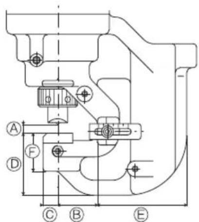
A:8.5mm
B:40mm
C:15mm
D:62.5mm
E:90mm
F:38.5mm
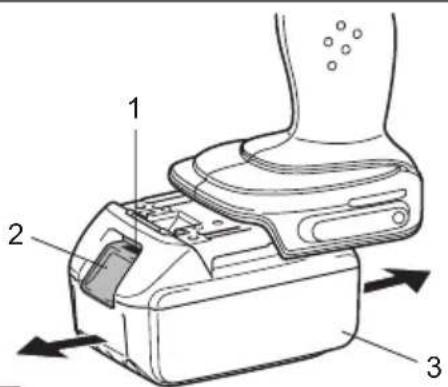
Fig.1
Fig.2
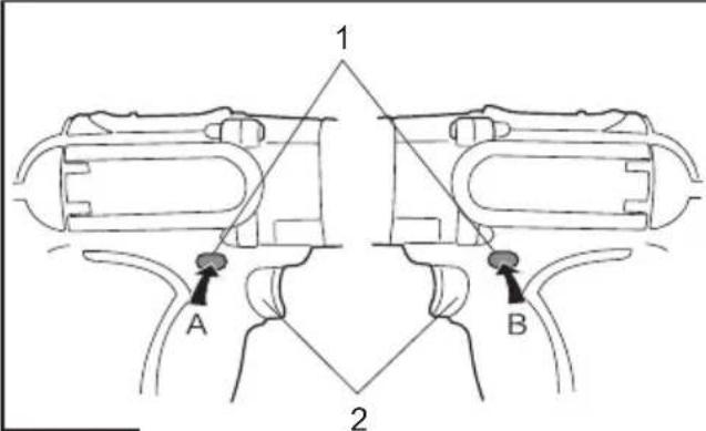
Fig.4
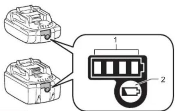
Fig.3
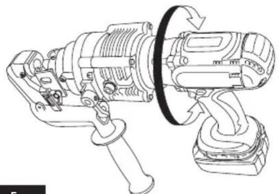
Fig.5
SPECIFICATIONS
| Model: DPP200 | ||
| Max. throat depth 40 mm | ||
| Shape of holes Round / Oblong | ||
| Max. hole size and thickness For | mild steel of 65,000 psi tensile strength | Diameter : 20 mm Thickness : 8 mm |
| For stainless steel of 89,000 psi tensile strength | Diameter : 20 mm Thickness : 6 mm | |
| Rated voltage D.C. 18 V | ||
| Dimensions (L x W x H) (with handle) | 417 mm x 127 mm x 315 mm | |
| Net weight 10.7 - 10.8 kg | ||
- Due to our continuing program of research and development, the specifications herein are subject to change without notice.
- Specifications may differ from country to country.
Weight, with battery cartridge, according to EPTA-Procedure 01/2014
Applicable battery cartridge and charger
| Battery cartridge BL1830B / BL1840B / BL1850B / BL1860B | |
| Charger DC18RC / DC18RD / DC18RE / DC18SD / DC18SE / DC18SF / DC18SH |
Some of the battery cartridges and chargers listed above may not be available depending on your region of residence.

WARNING: Only use the battery cartridges and chargers listed above. Use of any other battery cartridges and chargers may cause injury and/or fire.
Combination of punch and die
Round punching
| Punch Die Workpiece Capacity | |||
| Flat bar Max: 80 mm x t8 (Center punching) | |||
| Angle | Min: 40 mm x 40 mm x t3 Max: 80 mm x 80 mm x t8 | ||
| Channel | Min: 75 mm x 40 mm Max: 100 mm x 50 mm (Flange punching) | ||
Unit: mm
| Punch Die | Tensile Channel Tensile | Mild Steel (65,000 psi) Stainless Steel (89,000 psi) | ||
| 6 SB6 | t2 - t4 - t3 - t4 | |||
| 6.5 SB6 | t5 t2 - t6 - t3 - t4 | |||
| 8 SB8 | t2 - t6 - t3 - t4 | |||
| 8.5 SB8 | t5 t2 - t6 - t3 - t4 | |||
| 10 | SB10 | t2 - t6 | t7.5 | t3 - t4 |
| 11 | SB11 | t2 - t8 | t7.5 | t3 - t6 |
| 12 | SB12 | t2 - t8 | t7.5 | t3 - t6 |
| 13 | SB13 | t2 - t8 | t7.5 | t3 - t6 |
| 14 | SB14 | t2 - t8 | t7.5 | t3 - t6 |
| 15 | SB15 | t2 - t8 | t7.5 | t3 - t6 |
| 16 | SB16 | t2 - t8 | t7.5 | t3 - t6 |
| 18 | SB18 | t2 - t8 | t7.5 | t3 - t6 |
| 19 | SB19 | t2 - t8 | t7.5 | t3 - t6 |
| 20 | SB20 | t2 - t8 | t7.5 | t3 - t6 |
Oblong punching
Unit: mm
| Punch Die Workpiece Capacity | |||
| Flat bar Max: 80 mm x t8 (Center punching) | |||
| Angle | Min: 40 mm x 40 mm x t3 Max: 80 mm x 80 mm x t8 | ||
| Channel | Min: 75 mm x 40 mm Max: 100 mm x 50 mm (Flange punching) | ||
| Punch Die | Tensile Channel | Tensile | less Steel (89,000 psi) | |
| Mild Steel (65,000 psi) Stainless | ||||
| 6.5 x 10 6.5 | 5 x 10B t2 - t6 | - t3 - t4 | ||
| 6.5 x 13 6.5 | 5 x 13B t2 - t6 | - t3 - t4 | ||
| 8.5 x 13 8.5 | 5 x 13B t2 - t6 | - t3 - t4 | ||
| 8.5 x 17 8.5 | 5 x 17B t2 - t6 | - t3 - t4 | ||
| 9 x 13.5 9 | x 13.5B t2 - t6 | - t3 - t4 | ||
| 9 x 18 9 x | 18B t2 - t6 - t3 - t4 | |||
| 10 x 15 10 | x 15B t2 - t8 | t7.5 | t3 - t6 | |
| 10 x 20 10 | x 20B t2 - t8 | t7.5 | t3 - t6 | |
| 11 x 16.5 | 11 x 16.5B | t2 - t8 | t7.5 | t3 - t6 |
| 12 x 18 | 12 x 18B | t2 - t8 | t7.5 | t3 - t6 |
| 13 x 19.5 | 13 x 19.5B | t2 - t8 | t7.5 | t3 - t6 |
| 14 x 21 | 14 x 21B | t2 - t8 | t7.5 | t3 - t6 |
Symbols
The followings show the symbols used for the equipment. Be sure that you understand their meaning before use.
| Read instruction manual. | |
| Flying debris and loud noise hazards. Wear ear and eye protection. | |
| Hazardous voltage. Disconnect all power before working on this equipment. Failure to observe this instruction may result in death or personal injury. | |
| Moving blade. Keep hands clear while machine is operating. Turn power off before servicing. |

Ni-MH Li-ion
Only for EU countries
Do not dispose of electric equipment or battery pack together with household waste material! In observance of the European Directives, on Waste Electric and Electronic Equipment and Batteries and Accumulators and Waste Batteries and Accumators and their implementation in accordance with national laws, electric equipment and batteries and battery pack(s) that have reached the end of their life must be collected separately and returned to an environmentally compatible recycling facility.
Intended use
This tool is intended for piercing a hole on steel material.
Noise
The typical A-weighted noise level determined according to EN 60745-1, EN ISO 3744:
Sound pressure level (L_PA):76.7 dB(A)
Uncertainty (K): 3 dB(A)
NOTE: The declared noise emission value(s) has been measured in accordance with a standard test method and may be used for comparing one tool with another.
NOTE: The declared noise emission value(s) may also be used in a preliminary assessment of exposure.

WARNING: Wear ear protection.
WARNING: The noise emission during actual use of the power tool can differ from the declared value(s) depending on the ways in which the tool is used especially what kind of workpiece is processed.
WARNING: Be sure to identify safety measures to protect the operator that are based on an estimation of exposure in the actual conditions of use (taking account of all parts of the operating cycle such as the times when the tool is switched off and when it is running idle in addition to the trigger time).
Vibration
The vibration total value (tri-axial vector sum) determined according to EN 60745-1:
Vibration emission (a_h):2.5m / s^2 or less
Uncertainty (K): 1.5m / s^2
NOTE: The declared vibration total value(s) has been measured in accordance with a standard test method and may be used for comparing one tool with another.
NOTE: The declared vibration total value(s) may also be used in a preliminary assessment of exposure.

WARNING: The vibration emission during actual use of the power tool can differ from the declared value(s) depending on the ways in which the tool is used especially what kind of workpiece is processed.

WARNING: Be sure to identify safety measures to protect the operator that are based on an estimation of exposure in the actual conditions of the (taking account of all parts of the operating cycle such as the times when the tool is switched off and when it is running idle in addition to the trigger time).
EC Declaration of Conformity
For European countries only
The EC declaration of conformity is included as Annex A to this instruction manual.
SAFETYWARNINGS
General power tool safety warnings
WARNING: Read all safety warnings, instructions, illustrations and specifications provided with this power tool. Failure to follow all instructions listed below may result in electric shock, fire and/or serious injury.
Save all warnings and instructions for future reference.
The term "power tool" in the warnings refers to your mains-operated (corded) power tool or battery-operated (cordless) power tool.
Work area safety
- Keep work area clean and well lit. Cluttered or dark areas invite accidents.
- Do not operate power tools in explosive atmospheres, such as in the presence of flammable liquids, gases or dust. Power tools create sparks which may ignite the dust or fumes.
- Keep children and bystanders away while operating a power tool. Distractions can cause you to lose control.
Electrical safety
- Power tool plugs must match the outlet. Never modify the plug in any way. Do not use any adapter plugs with earthed (grounded) power tools. Unmodified plugs and matching outlets will reduce risk of electric shock.
- Avoid body contact with earthed or grounded surfaces, such as pipes, radiators, ranges and refrigerators. There is an increased risk of electric shock if your body is earthed or grounded.
- Do not expose power tools to rain or wet conditions. Water entering a power tool will increase the risk of electric shock.
- Do not abuse the cord. Never use the cord for carrying, pulling or unplugging the power tool. Keep cord away from heat, oil, sharp edges or moving parts. Damaged or entangled cords increase the risk of electric shock.
- When operating a power tool outdoors, use an extension cord suitable for outdoor use. Use of a cord suitable for outdoor use reduces the risk of electric shock.
- If operating a power tool in a damp location is unavoidable, use a residual current device (RCD) protected supply. Use of an RCD reduces the risk of electric shock.
- Power tools can produce electromagnetic fields (EMF) that are not harmful to the user. However, users of pacemakers and other similar medical devices should contact the maker of their device and/or doctor for advice before operating this power tool.
Personal safety
-
Stay alert, watch what you are doing and use common sense when operating a power tool. Do not use a power tool while you are tired or under the influence of drugs, alcohol or medication. A moment of inattention while operating power tools may result in serious personal injury.
-
Use personal protective equipment. Always wear eye protection. Protective equipment such as a dust mask, non-skid safety shoes, hard hat or hearing protection used for appropriate conditions will reduce personal injuries.
- Prevent unintentional starting. Ensure the switch is in the off-position before connecting to power source and/or battery pack, picking up or carrying the tool. Carrying power tools with your finger on the switch or energising power tools that have the switch on invites accidents.
- Remove any adjusting key or wrench before turning the power tool on. A wrench or a key left attached to a rotating part of the power tool may result in personal injury.
- Do not overreach. Keep proper footing and balance at all times. This enables better control of the power tool in unexpected situations.
- Dress properly. Do not wear loose clothing or jewellery. Keep your hair and clothing away from moving parts. Loose clothes, jewellery or long hair can be caught in moving parts.
- If devices are provided for the connection of dust extraction and collection facilities, ensure these are connected and properly used. Use of dust collection can reduce dust-related hazards.
- Do not let familiarity gained from frequent use of tools allow you to become complacent and ignore tool safety principles. A careless action can cause severe injury within a fraction of a second.
- Always wear protective goggles to protect your eyes from injury when using power tools. The goggles must comply with ANSI Z87.1 in the USA, EN 166 in Europe, or AS/NZS 1336 in Australia/New Zealand. In Australia/New Zealand, it is legally required to wear a face shield to protect your face, too.
It is an employer's responsibility to enforce the use of appropriate safety protective equipments by the tool operators and by other persons in the immediate working area.
Power tool use and care
- Do not force the power tool. Use the correct power tool for your application. The correct power tool will do the job better and safer at the rate for which it was designed.
-
Do not use the power tool if the switch does not turn it on and off. Any power tool that cannot be controlled with the switch is dangerous and must be repaired.
-
Disconnect the plug from the power source and/or remove the battery pack, if detachable, from the power tool before making any adjustments, changing accessories, or storing power tools. Such preventive safety measures reduce the risk of starting the power tool accidentally.
- Store idle power tools out of the reach of children and do not allow persons unfamiliar with the power tool or these instructions to operate the power tool. Power tools are dangerous in the hands of untrained users.
- Maintain power tools and accessories. Check for misalignment or binding of moving parts, breakage of parts and any other condition that may affect the power tool's operation. If damaged, have the power tool repaired before use. Many accidents are caused by poorly maintained power tools.
- Keep cutting tools sharp and clean. Properly maintained cutting tools with sharp cutting edges are less likely to bind and are easier to control.
- Use the power tool, accessories and tool bits etc. in accordance with these instructions, taking into account the working conditions and the work to be performed. Use of the power tool for operations different from those intended could result in a hazardous situation.
- Keep handles and grasping surfaces dry, clean and free from oil and grease. Slippery handles and grasping surfaces do not allow for safe handling and control of the tool in unexpected situations.
- When using the tool, do not wear cloth work gloves which may be entangled. The entanglement of cloth work gloves in the moving parts may result in personal injury.
Battery tool use and care
- Recharge only with the charger specified by the manufacturer. A charger that is suitable for one type of battery pack may create a risk of fire when used with another battery pack.
- Use power tools only with specifically designated battery packs. Use of any other battery packs may create a risk of injury and fire.
- When battery pack is not in use, keep it away from other metal objects, like paper clips, coins, keys, nails, screws or other small metal objects, that can make a connection from one terminal to another. Shorting the battery terminals together may cause burns or a fire.
- Under abusive conditions, liquid may be ejected from the battery; avoid contact. If contact accidentally occurs, flush with water. If liquid contacts eyes, additionally seek medical help. Liquid ejected from the battery may cause irritation or burns.
- Do not use a battery pack or tool that is damaged or modified. Damaged or modified batteries may exhibit unpredictable behaviour resulting in fire, explosion or risk of injury.
- Do not expose a battery pack or tool to fire or excessive temperature. Exposure to fire or temperature above 130^ may cause explosion.
- Follow all charging instructions and do not charge the battery pack or tool outside the temperature range specified in the instructions. Charging improperly or at temperatures outside the specified range may damage the battery and increase the risk of fire.
Service
- Have your power tool serviced by a qualified repair person using only identical replacement parts. This will ensure that the safety of the power tool is maintained.
- Never service damaged battery packs. Service of battery packs should only be performed by the manufacturer or authorized service providers.
- Follow instruction for lubricating and changing accessories.
Safety instructions for Cordless Hole Puncher
- Proper selection of the punch and the die is essential. Select the correct punch and die according to the hole shape, size of hole, workpiece thickness and material type.
- Ensure that any punch with stepped edge, which prevents free rotation, is installed correctly in the punch piston before tightening the punch retaining nut.
- For punching channel-shaped workpiece and the workpiece made of stainless steel, use the die provided exclusively for these materials. Only select the combination of the punch and die that is suitable for the workpiece thickness.
- Ensure the punch and the die are firmly fixed in position with the nut or the bolt. Failure to do so may cause serious damage to your tool and serious personal injury. Regularly check and tighten the punch and die.
- The tool is electro-hydraulic. When the temperature is cold, it should be run for a few minutes at idle before starting operations.
- Keep face, hands and other parts of your body away from the punching area during operation.
- Remove the battery cartridge before changing the punch and the die or when servicing or making adjustments.
- The punch and the die that become worn, deformed, nicked, broken or damaged in any way may cause a tool breakdown and a serious accident. Replace them immediately with new ones supplied from Makita.
- When punching stainless steel, the punch and die may wear earlier than punching softer materials. Ensure that the punch and die are in good condition, free from wear and are not deformed, nicked, broken or damaged in any way. Check with your dealer before punching any material not listed in the specifications.
- Remove and check the carbon brushes regularly. Replace them after 200 times of use. Carbon brushes with a length of about 6mm or less may cause damage to the motor.
- When using the tool continuously, its temperature can exceed 70^ which may cause lower performance. In this case, stop operating for about 1 hour to allow the tool to cool down before using it again.
- Do not cover or clog the motor air vents as this may cause the motor to overheat, resulting in smoke, fire and explosion.
Important safety instructions for battery cartridge
- Before using battery cartridge, read all instructions and cautionary markings on (1) battery charger, (2) battery, and (3) product using battery.
- Do not disassemble battery cartridge.
- If operating time has become excessively shorter, stop operating immediately. It may result in a risk of overheating, possible burns and even an explosion.
- If electrolyte gets into your eyes, rinse them out with clear water and seek medical attention right away. It may result in loss of your eyesight.
- Do not short the battery cartridge:
(1) Do not touch the terminals with any conductive material.
(2) Avoid storing battery cartridge in a container with other metal objects such as nails, coins, etc.
(3) Do not expose battery cartridge to water or rain. A battery short can cause a large current flow, overheating, possible burns and even a breakdown.
- Do not store the tool and battery cartridge in locations where the temperature may reach or exceed 50^ (122^) .
- Do not incinerate the battery cartridge even if it is severely damaged or is completely worn out. The battery cartridge can explode in a fire.
- Be careful not to drop or strike battery.
- Do not use a damaged battery.
- The contained lithium-ion batteries are subject to the Dangerous Goods Legislation requirements. For commercial transports e.g. by third parties, forwarding agents, special requirement on packaging and labeling must be observed.
For preparation of the item being shipped, consulting an expert for hazardous material is required. Please also observe possibly more detailed national regulations.
Tape or mask off open contacts and pack up the battery in such a manner that it cannot move around in the packaging.
- When disposing the battery cartridge, remove it from the tool and dispose of it in a safe place. Follow your local regulations relating to disposal of battery.
- Use the batteries only with the products specified by Makita. Installing the batteries to non-compliant products may result in a fire, excessive heat, explosion, or leak of electrolyte.
- If the tool is not used for a long period of time, the battery must be removed from the tool.
SAVE THESE INSTRUCTIONS.
CAUTION: Only use genuine Makita batteries.
Use of non-genuine Makita batteries, or batteries that have been altered, may result in the battery bursting causing fires, personal injury and damage. It will also void the Makita warranty for the Makita tool and charger.
Tips for maintaining maximum battery life
-
Charge the battery cartridge before completely discharged. Always stop tool operation and charge the battery cartridge when you notice less tool power.
-
Never recharge a fully charged battery cartridge. Overcharging shortens the battery service life.
- Charge the battery cartridge with room temperature at 10^ - 40^ (50^ - 104^) . Let a hot battery cartridge cool down before charging it.
- Charge the battery cartridge if you do not use it for a long period (more than six months).
PARTS DESCRIPTION
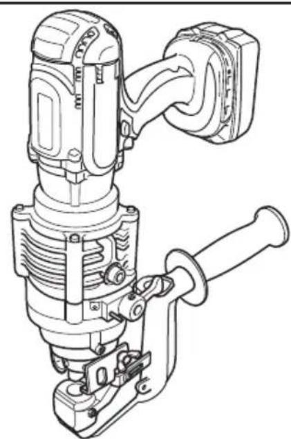
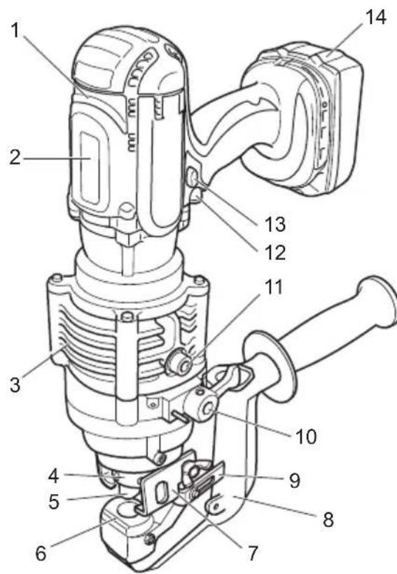
Fig.1
| 1 | Motor | 2 | Safety label | 3 | Pump case | 4 | Punch retaining nut |
| 5 | Punch | 6 | Die | 7 | Stripper | 8 | C frame |
| 9 | Slide stopper | 10 | Return lever | 11 | Oil port | 12 | Switch trigger |
| 13 | Trigger lock button | 14 | Battery cartridge | - | - | - | - |
FUNCTIONAL DESCRIPTION
CAUTION: Always be sure that the tool is switched off and the battery cartridge is removed before adjusting or checking function on the tool.
Installing or removing battery cartridge
CAUTION: Always switch off the tool before installing or removing of the battery cartridge.
CAUTION: Hold the tool and the battery cartridge firmly when installing or removing battery cartridge. Failure to hold the tool and the battery cartridge firmly may cause them to slip off your hands and result in damage to the tool and battery cartridge and a personal injury.
Fig.2: 1. Red indicator 2. Button 3. Battery cartridge
To remove the battery cartridge, slide it from the tool while sliding the button on the front of the cartridge.
To install the battery cartridge, align the tongue on the battery cartridge with the groove in the housing and slip it into place. Insert it all the way until it locks in place with a little click. If you can see the red indicator on the upper side of the button, it is not locked completely.
CAUTION: Always install the battery cartridge fully until the red indicator cannot be seen. If not, it may accidentally fall out of the tool, causing injury to you or someone around you.
CAUTION: Do not install the battery cartridge forcibly. If the cartridge does not slide in easily, it is not being inserted correctly.
Battery protection system
The tool is equipped with a battery protection system. This system automatically cuts off power to the motor to extend tool and battery life. The tool will automatically stop during operation if the tool or battery is placed under the following condition.
Overdischarge protection
When the battery capacity is not enough, the tool stops automatically. In this case, remove the battery from the tool and charge the battery.
Indicating the remaining battery capacity
Only for battery cartridges with the indicator
Fig.3: 1. Indicator lamps 2. Check button
Press the check button on the battery cartridge to indicate the remaining battery capacity. The indicator lamps light up for a few seconds.
| Indicator lamps | Remaining capacity | ||
| Lighted | Off | Blinking | |
| 75% to 100% | |||
| 50% to 75% | |||
| 25% to 50% | |||
| 0% to 25% | |||
| Charge the battery. | |||
| The battery may have malfunctioned. | |||
NOTE: Depending on the conditions of use and the ambient temperature, the indication may differ slightly from the actual capacity.
Switch action
CAUTION: Before installing the battery cartridge into the tool, always check to see that the switch trigger actuates properly and returns to the "OFF" position when released.
CAUTION: Always lock the switch trigger when not in use.
When punching a workpiece, continue to pull the switch trigger until the punch goes down to the die and returns to the start position.
To lock the switch trigger, push in the trigger lock button from B side. To unlock, push in the trigger lock button from A side
Fig.4: 1. Trigger lock button 2. Switch trigger
Rotatable grip
The grip can be rotated though 360 degrees, in either direction, during operation. This feature is particularly useful when working in awkward or narrow areas as it allows the operator to position the tool in the best position for easy operation.
Fig.5
ASSEMBLY
CAUTION: Always be sure that the tool is switched off and the battery cartridge is removed before carrying out any work on the tool.
Replacing the punch and die
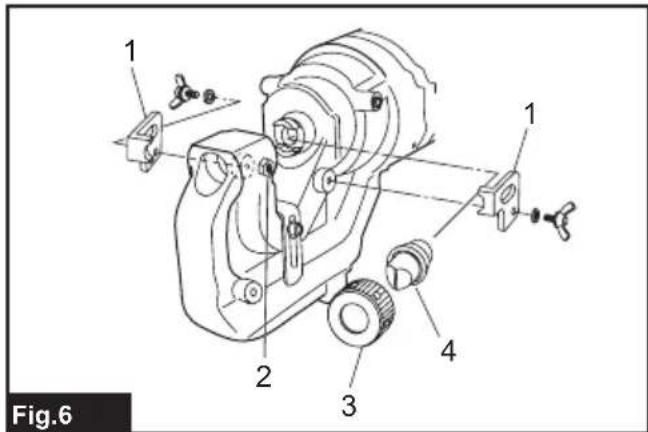
Replacing round punch
▶ Fig.6: 1. Stripper 2. Nut and set bolt 3. Punch retaining nut 4. Round punch
- Be sure that the punch piston is fully retracted and remove the strippers to make access to the parts easier.
- The punch must be removed first and then the die. Unscrew the punch retaining nut to remove the punch and remove the set bolt and the nut to remove the die.
NOTICE: When replacing the punch and the die, make sure that the correct size, thickness and hole shape is selected. Shaped punches and dies must be properly aligned with each other.
- Place the die in the C frame in the proper orientation. Secure firmly with the set bolt and tighten the nut.
- Place the punch in the punch retaining nut. Insert the punch with the nut into the punch piston and hand tighten the nut.
NOTICE: When installing a punch with a stepped edge (anti rotation), make sure the orientation is correct and that the stepped edge is correctly positioned in the punch piston.
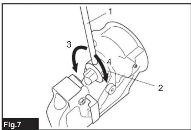
- Make sure the punch is correctly positioned in the punch rod and tighten the punch retaining nut firmly with the nut retaining bar supplied.
Fig.7: 1. Nut retaining bar 2. Punch retaining nut 3. Loosen 4. Tighten
WARNING: If the punch and die are not the same size or the punch and the die are not positioned properly, the punch may strike the die causing both parts to break. In such a case, pieces flying off from the broken parts may cause personal injury.
CAUTION: Check the butterfly bolts which hold the stripper regularly to ensure that they are tight. Loose bolts may cause the stripper to come off and damage the tool.
Replacing oblong punch
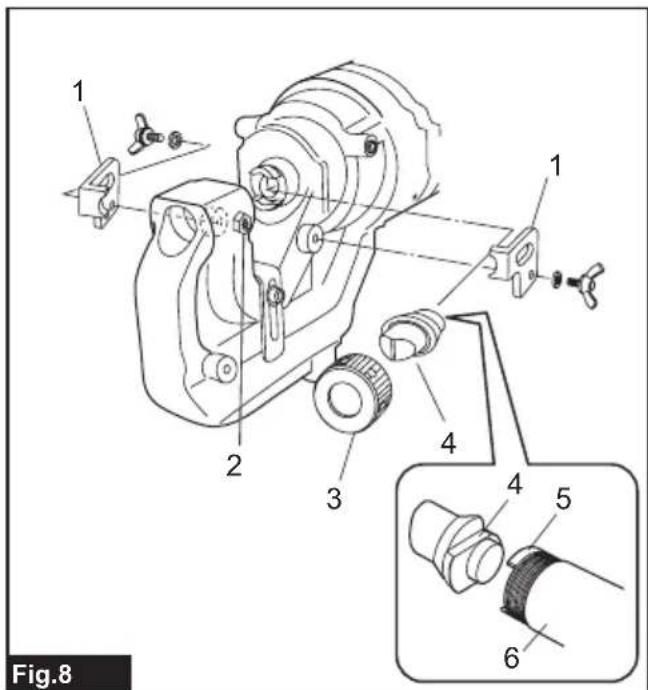
▶ Fig.8: 1. Stripper 2. Nut and set bolt 3. Punch retaining nut 4. Oblong punch 5. Stepped edge 6. Punch rod
- Be sure that the punch piston is fully retracted and remove the strippers to make access to the parts easier.
- The punch must be removed first and then the die. Unscrew the punch retaining nut to remove the punch and remove the set bolt and the nut to remove the die.
NOTICE: When replacing the punch and the die, make sure that the correct size, thickness and hole shape is selected. Shaped punches and dies must be properly aligned with each other.
- Secure the oblong die firmly with the set bolt and tighten the nut.
- Place the oblong punch into the punch retaining nut. Position the stepped edge of the oblong punch properly in the punch piston and hand tighten the punch retaining nut.
NOTICE: If the stepped edge of the oblong punch is not properly inserted into the punch piston, the punch retaining nut cannot be fastened. Make sure the oblong punch is positioned correctly in the punch rod.
-
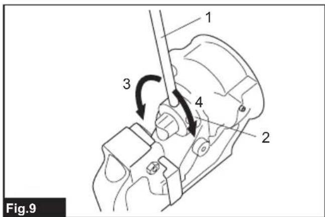
Push the oblong punch against the punch rod and tighten the punch retaining nut firmly with the nut firmly with the nut retaining bar supplied.
▶ Fig.9: 1. Nut retaining bar 2. Punch retaining nut 3. Loosen 4. Tighten -
Restore the strippers.
WARNING: If the punch and die are not the same size or the punch and the die are not positioned properly, the punch may strike the die causing both parts to break. In such a case, pieces flying off from the broken parts may cause personal injury.
CAUTION: Check the butterfly bolts which hold the stripper regularly to ensure that they are tight. Loose bolts may cause the stripper to come off and damage the tool.
CAUTION: Make sure the stepped edge of the oblong punch is positioned correctly in the punch rod and the punch retaining nut is properly fastened.
OPERATION
Correct use of the tool
Die selection
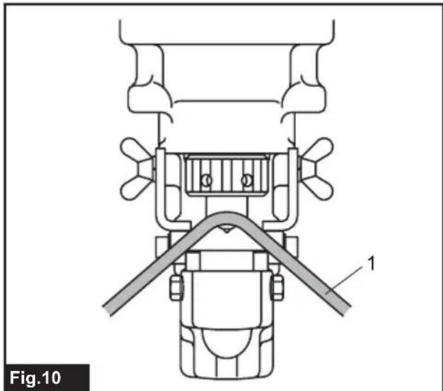
It is important that the die to be used is correct for the thickness of the workpiece to be punched. Punching the workpiece of 4mm to 8mm thickness using a die for thinner workpiece can cause the punch to jam in the workpiece. This is due to the smaller clearance between the die and punch. In such a case, the workpiece will be pulled up by the retracting punch as shown in the figure. Special care should be taken when punching flat bar of mild steel, aluminum and copper.
Fig.10: 1.Workpiece
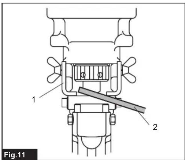
Correct use of the stripper
Do not position the workpiece with one end or both ends unsupported by the stripper. If the workpiece is not properly supported, it will move when the punch returns. It may cause the punch to jam and damaging the tool.
▶ Fig.11: 1. Stripper 2. Workpiece
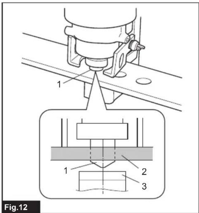
Punching a hole
CAUTION: Before punching, always make sure that the proper punch and die are installed correctly.
- Check the position for punching.
Fig.12: 1. Punch 2. Flat bar 3. Die - Loosen the cap screw on the slide stopper and adjust the slide stopper to the desired position. After that, retighten the cap screw.
NOTE: The slide stopper is set to hold the hole puncher at a constant distance from the edge of the work piece.
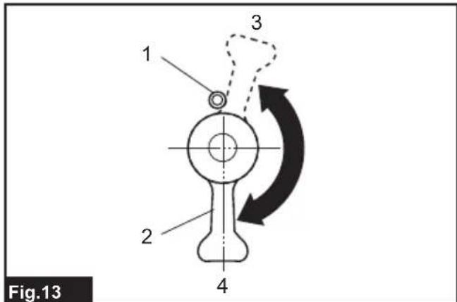
- Check that the return lever is fully closed in the clockwise direction.
Fig.13: 1. Spring pin 2. Return lever 3. Open position 4. Closed position
- Check that the punch piston is fully retracted.
- Place the puncher in the required position on the workpiece using the slide stopper as a guide. Align the point of the punch with the center mark of the hole to be punched.
- Continue to pull the switch trigger until the punch reaches the end of its stroke and returns to the starting position.
The punch rod will extend and push the punch through the workpiece.
NOTE: To aid accurate and easy positioning of the punch, pull the switch trigger intermittently to jog the punch down to the workpiece. If the position is not satisfactory, open the return lever to retract the punch for another attempt. If the punch doesn't return to its starting position with return lever open, pull the switch trigger to return the punch.
NOTE: If the punch doesn't return after punching finishes, release the switch trigger to stop the motor and pull the switch trigger again.
If the punch doesn't return even after performing above procedures, perform the procedures for stopping the operation before the completion of punching mentioned below.
Stopping the operation before the punching is finished
If you want to stop the operation before the punching is finished, perform the procedures below:
- Turn the return lever counterclockwise until it hits the spring pin and then immediately back to its starting position.
Doing this releases the internal pressure of the tool. If the punch retracts from the workpiece under its own power, allow the punch to fully return. After that, turn the return lever back to its starting position. In this case, the following step is not necessary. - Continue to pull the switch trigger until the punch returns to its starting position.
Using slide stopper for maximum depth
Optional accessory
CAUTION: Before attaching or removing the slide stopper, ensure that the battery cartridge is removed to prevent accidental operation and personal injury.
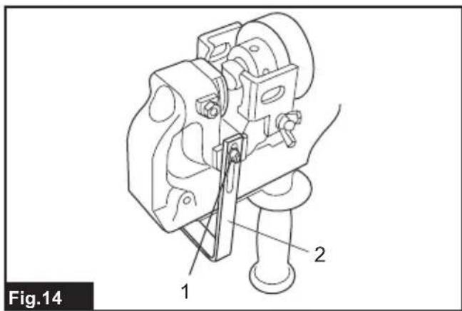
Punching up to 40mm depth from the edge of the workpiece can be done using the optional slide stopper.
Fig.14: 1. Bolt and washer 2. Optional slide stopper
- Loosen the set bolt and nut to remove the die.
- Remove the bolt and washer fixing the slide stopper.
- Remove the slide stopper by pulling it to the upper side of the C frame.
- Insert the optional slide stopper for maximum depth from the bottom side of the C frame.
- Fix the optional slide stopper with the bolt and washer removed in step 2.
- Install the die with the set bolt and nut removed in step 1.
MAINTENANCE
CAUTION: Always be sure that the tool is switched off and the battery cartridge is removed before attempting to perform inspection or maintenance.
NOTICE: Never use gasoline, benzine, thinner, alcohol or the like. Discoloration, deformation or cracks may result.
To maintain product SAFETY and RELIABILITY, repairs, any other maintenance or adjustment should be performed by Makita Authorized or Factory Service Centers, always using Makita replacement parts.
Regular maintenance
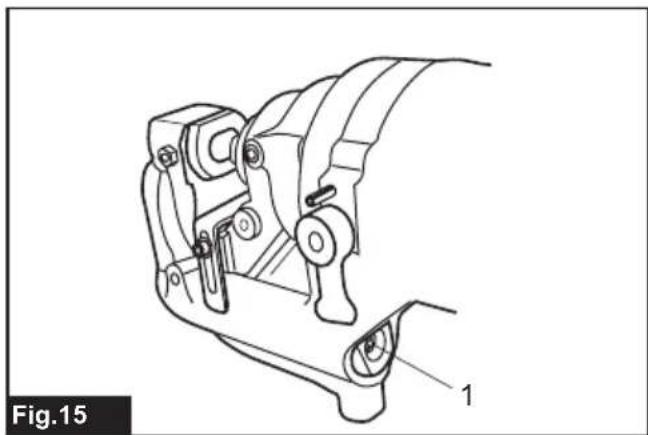
Keep the air hole at the end of the C frame clear of dirt and obstructions. The air hole has to be open in order to control the hydraulic pressure.
Fig.15: 1. Air hole
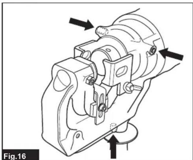
Do not undo or remove the three screws as shown in the figure. Doing so will cause oil to leak from the tool.
Fig.16
Addling oil
This tool is electro-hydraulic. When shipped from the factory, it was filled with the oil. Do not attempt to add oil as long as the tool performs well. When the oil-pressure is not enough for proper operation, add oil in the following procedures.
NOTICE: Make sure that the work area and all equipment is clean so that no dirt, dust or other foreign materials can get into the hydraulic oil or pump area.
NOTICE: Only use pure hydraulic oil recommended by Makita. To prevent damage to the seals and other internal machine parts, do not use other oil listed below.
Recommended oil:
-
Makita hydraulic oil
Super Hyrando #46 (JXTG Nippon Oil & Energy Corp.)
Shell Tellus Plus #46 (U.S. Shell)
Hydraulic oil with equivalent spec anti-wear, ISO Viscosity Grade 46. -
Install the battery cartridge to the tool.
- Lay the tool on its left side so that the oil port is facing up.
- Operate the tool to move the punch position almost to the bottom of its stroke.
NOTE: If necessary, run the tool for several strokes. Doing so allows you to determine the bottom of stroke and also position the punch piston correctly. In the correct position, the maximum amount of oil has been drawn from the pump and the appropriate amount of oil for refill can be obtained.
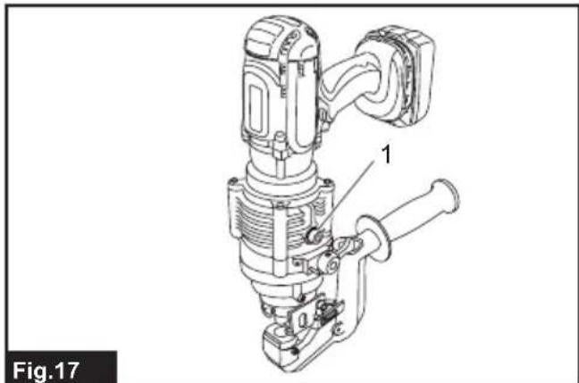
- Remove the battery cartridge from the tool.
- Carefully remove the socket head cap screw to open the oil port.
Fig.17: 1. Socket head cap screw
- Fill the reservoir with hydraulic oil using the small squeeze bottle which is supplied with the tool.
- Rock the tool back and forth slightly several times to free any trapped air bubbles. After that, add additional oil as necessary.
- Replace the socket head cap screw and wipe up any excess oil.
- Install the battery cartridge and run the tool for several strokes with the return lever is in open position. After that, run the tool again with the return lever is in closed position.
Doing this purges trapped air out of the system. Repeat this procedure to make sure that the punch piston is almost at the bottom of its stroke.
- Add additional oil as necessary by repeating step 3 to 9.
If the oil is depleted excessively, you need to repeat this procedure several times.
Replacing carbon brushes
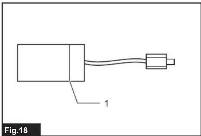
Replace the carbon brushes when they wear down to the limit mark.
NOTICE: Keep the carbon brushes clean and free to slip in the holders.
NOTICE: Both carbon brushes must be replaced at the same time.
NOTICE: Use only identical carbon brushes.
Fig.18: 1. Limit mark
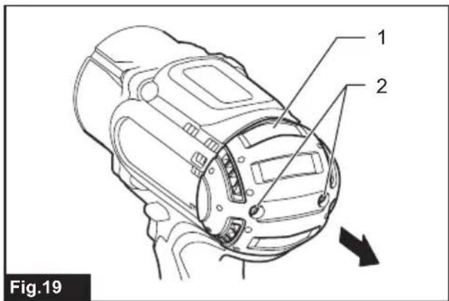
- Remove two screws on the rear cover using a screwdriver and then remove the rear cover.
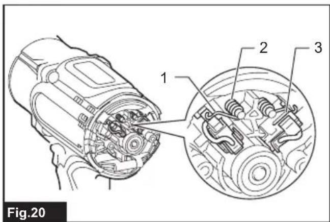
Fig.19: 1. Rear cover 2. Screw - Raise the arm part of the spring and then place it in the recessed part of the housing with a slotted bit screwdriver or the like.
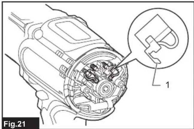
Fig.20: 1.Arm 2.Spring 3.Recessed part - Remove the carbon brush caps of the carbon brushes using pliers and then take out the worn carbon brushes. Insert the new carbon brushes and attach the carbon brush caps.
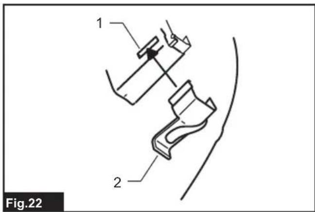
Fig.21: 1. Carbon brush cap - Make sure that the carbon brush caps have fit into the holes in brush holders securely.
Fig.22: 1.Hole 2. Carbon brush cap - Reinstall the rear cover and tighten two screws securely.
TROUBLESHOOTING
Before asking for repairs, conduct your own inspection first. If you find a problem that is not explained in the manual, do not attempt to dismantle the tool. Instead, ask Makita Authorized Service Centers, always using Makita replacement parts for repairs.
| State of abnormality Probable cause | (malfunction) Remedy | |
| Punch piston will not come out. Oil is | insufficient Refill oil. | |
| Punch piston has not returned completely due to rebar chips, iron powder and dirt in the sliding portion of punch piston and C frame. | Push back punch piston.Clean punch piston. | |
| Punch piston has not returned completely due to the distortion or swelling of punch piston. | Ask your local authorized service center for repair. | |
| Punch piston has not returned completely due to weak return spring. | Ask your local authorized service center for repair. | |
| Although punch piston comes out, cutting power is too weak to hole punching. | Oil is insufficient. Refill oil. | |
| Contact between cylinder and release valve is improper. There may be scratches at chimney of cylinder or iron powder or dirt are sticking there. | Ask your local authorized service center for repair. | |
| Breakage of release valve. Ask your local authorized service center for repair. | ||
| Improper clearance between cylinder and piston. | Ask your local authorized service center for repair. | |
| Improper contact between cylinder and check valve. | Ask your local authorized service center for repair. | |
| Breakage of urethane packing of cylinder. | Ask your local authorized service center for repair. | |
| Oil leaks. Scratches on or breakage of | oil levelersack. | Ask your local authorized service center for repair. |
| Scratches at sliding portion of C frame and punch piston and at back-up ring. | Ask your local authorized service center for repair. | |
| Breakage of O-ring at joint of C frame and cylinder. | Ask your local authorized service center for repair. | |
| Breakage of liner at joint of cylinder and pump case. | Ask your local authorized service center for repair. | |
| Insufficient tightening of bolts at respective parts. | Tighten bolts. | |
| Motor does not move.Poor motor rotation. | Insufficient charge of battery cartridge. | Charge battery cartridge. |
| Battery life cycle worn off. Replace batteries. | ||
| Breakage of motor by overheating. Ask your local authorized service center for repair. | ||
| Deformation or breakage of bearings and gear connected to the motor. | Ask your local authorized service center for repair. |
CAUTION: The internal components of the pump have very close clearances and are sensitive to damage from dust, dirt, contamination of the hydraulic fluid or improper handling. The disassembly of the pump housing requires special tools and training, and should only be attempted by repair personnel who have been properly trained and have the proper equipment. The improper servicing of electrical components can lead to conditions that could cause serious injury. The pump and piston components and all electrical components should be serviced only by authorized repair shop, dealer or distributor.
NOTICE: Any attempt by unauthorized personnel to service the internal components of the pump area will void the warranty.
OPTIONAL ACCESSORIES
CAUTION: These accessories or attachments are recommended for use with your Makita tool specified in this manual. The use of any other accessories or attachments might present a risk of injury to persons. Only use accessory or attachment for its stated purpose.
If you need any assistance for more details regarding these accessories, ask your local Makita Service Center.
Work stand
- Slide stopper (Max. throat depth)
- Makita genuine battery and charger
NOTE: Some items in the list may be included in the tool package as standard accessories. They may differ from country to country.
SPÉCIFICATIONS
ACCESSIONS EN OPTION
VEILIGHEIDSWAARSCHUWINGEN
OPTIONELE ACCESSOIRES
Móvo yia xwpe ts Eupwnns
H aumoppwos EK Tepiaaubavetai wS Naapaptna A oTo TApov yxεipidio odnyiw.
IPOEIAOIOIHSEIEA ΣΦΑΛΕΙΑΣ
EvikeπpoεiodoioηεicασφαλεiacyiaTO nλEKPTPIKO εpyaλεio
A NPOEIAOIOIHs: AiaBae 6AEs TIG POEI- BTOINOEi aopaleias, ONYIEc, EIKOVOPaPnoei KAI TPOBIAYPAeC TOU TAPEXOVTai ME auto To nEkTpiKo EPyAeio. H mtn npnon oawv twv oyniw v Tou avaypaoovtai KatWTepw MTOpei va kataaNfci OE nEkTpoTTnGia, TUPKayia h/kai oobapo tpaumatio.
IPEPIPAPH EAPTHMATQN
Eik.1
| Batarya kartuș BL1830B / BL1840B / BL1850B / BL1860B | |
| Şar aleti DC18RC / DC18RD / DC18RE / DC18SD / DC18SE / DC18SF / DC18SH |