
SP10RE - Turntable TECHNICS - Free user manual and instructions
Find the device manual for free SP10RE TECHNICS in PDF.
| Product Type | Direct drive turntable |
| Brand | Technics |
| Model | SP10RE |
| Motor | Brushless DC motor, coreless direct drive |
| Platter | Brass and die-cast aluminum with rubber sheet; diameter 323 mm, weight 7.9 kg |
| Rotation speeds | 33 1/3, 45, and 78 rpm (78.26 rpm for 78 rpm) |
| Pitch control range | ±16% |
| Starting torque | 0.39 N·m (4.0 kg·cm) |
| Wow and flutter | 0.015% weighted effective (JIS C5521) |
| Braking system | Electronic brake |
| Main unit dimensions | 365 × 109 × 365 mm |
| Control unit dimensions | 110 × 84 × 350 mm |
| Main unit weight | Approx. 18.2 kg |
| Control unit weight | Approx. 2.1 kg |
| Power supply | 110-240 V AC, 50/60 Hz |
| Power consumption | 10 W operation, 0.05 W standby |
| Operating temperature | 0 °C to 40 °C |
| Operating humidity | 35% to 80% RH (no condensation) |
| Platter construction | Three layers: brass, die-cast aluminum, damping rubber; tungsten peripheral weights |
| Furniture compatibility | Compatible with SP-10MK2 and SP-10MK3 furniture (same screw footprints) |
| Supplied accessories | 4 power cords (different countries), platter mat, 45 rpm adapter, set of 3 screws + washers + Belleville springs, 2 detachable handles |
| Cleaning and maintenance | Wipe with a soft, dry cloth; for stubborn dirt, use a well-wrung damp cloth |
| Safety instructions | Do not expose to rain, moisture, dripping, or splashing; do not obstruct ventilation openings |
Frequently Asked Questions - SP10RE TECHNICS
User questions about SP10RE TECHNICS
0 question about this device. Answer the ones you know or ask your own.
Ask a new question about this device
Download the instructions for your Turntable in PDF format for free! Find your manual SP10RE - TECHNICS and take your electronic device back in hand. On this page are published all the documents necessary for the use of your device. SP10RE by TECHNICS.
USER MANUAL SP10RE TECHNICS
Winsberging 15, 22525 Hamburg, Germany

For the U.S.A.
Panasonic Corporation of North America
Two Riverfront Plaza, Newark, NJ 07102-5490
www.shop.panasonic.com
For Canada / Pour le Canada
Panasonic Canada Inc.
5770 Amtioer Drive,
Mississauga, Ontario.
LW213
www.panasonic.com
© Panasonic Corporation 2018
For the United Kingdom and Ireland
For Continental Europe
Panasonic Corporation
Web Site: http://www.panasonic.com
EnCfGeF11SpDuSwDaPb
TOBMO219
S0210620140001
SP-10R
Direct Drive Turntable
Operating Instructions
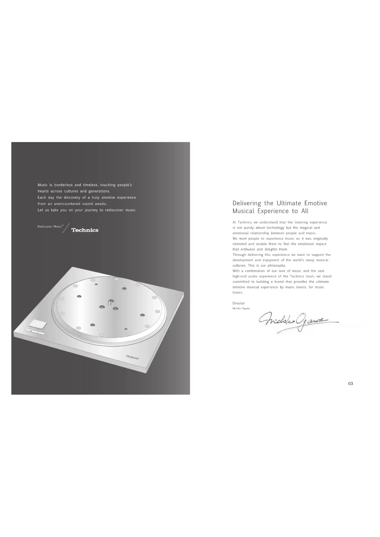
Delivering the Ultimate Emotive Musical Experience to All
At Technics we understand that the listening experience is not purely about technology but the magical and emotional relationship between people and music.
We want people to experience music as it was originally intended and enable them to feel the emotional impact that enthuses and delights them.
Through delivering this experience we want to support the development and enjoyment of the world's many musical cultures. This is our philosophy.
With a combination of our love of music and the vast high end audio experience of the Technics team, we stand committed to building a brand that provides the ultimate emotive musical experience by music lovers, for music lovers.
Director
Michiko Ogezaki
nichke Oogaa
Thank you for purchasing this product.
Please read these instructions carefully before using this product, and save this manual for future use.
- About descriptions in these operating instructions
- Pages to be referred to are indicated as "( 00 )"
- The illustrations shown may differ from your unit
For the U.S.A. and Canada
If you have any questions, visit: U.S.A.: http://shop.panasonic.com/support Canada: www.panasonic.ca/english/support Register online at http://shop.panasonic.com/support (U.S. customers only)
For the United Kingdom and Ireland customers
Sales and Support Information
Customer Communications Centre
For customers within the UK: 0333 222 8777
For customers within Ireland: 01 447 5229
Monday-Friday 9:00 am - 5:00 pm (Excluding public holidays).
For further support on your product, please visit our website: www.technics.com/uk/
Features
Coreless direct drive motor for smooth and accurate rotation
- The new coreless direct drive motor can reduce minute vibration during rotation by ensuring strong torque to drive the grand class turntable.
- The high-precision motor control technology changes the drive mode according to the motor operation status to achieve high rotation accuracy.
Three-layer turntable for stable rotation
The three-layer turntable structure is consisting of brass, aluminum die cast and deadening rubber that is against unwanted resonance and attached to the bottom surface.
- Dense tungsten weights are located on the outer periphery of the brass part to deliver large inertial mass.
Special control unit that can eliminate unwanted noise interference with the main unit
- The power circuit and control circuit are separated to minimize unwanted external noise interference with the main unit and stored in a single control unit.
- The new switching power supply with a noise reduction circuit has been developed to reduce noise in voltage supply.
Compatibility with SP-10MK2 and SP-10MK3
- The player preserves the bottom shape and screw locations of SP-10MK2 and SP-10MK3 so that you can continue to use your cabinet and tone arm.
Table of contentsIntroduction
Before use
| Safety precautions | 06 |
| IMPORTANT SAFETY INSTRUCTIONS | 07 |
| Accessories | 09 |
| Parts Name | 10 |
Getting started
Unpacking and preparation 12
Notes for taking out the goods from the package box and transporting... 12
Putting the player together... 13
- Before putting the player together
(Regarding the cabinet and tone arm) 13 - Mounting to the cabinet 13
- Fitting the turntable 15
- Fitting the turntable mat 15
- Connections and installation 15
- Connecting the control unit / Connecting the power plug and earth ground 16
- Installation 17
Playing back
| Playing records | 18 |
| Pitch control (fine adjustment to pitch) | 20 |
| Operation and display of the control unit | 21 |
| - Turntable speed setting | 21 |
| - Switching the display mode | 21 |
| - Turntable speed measurement | 21 |
| - Display dimmer setting | 22 |
| - Adjusting the torque to rotate the turntable at a constant speed | 22 |
Maintenance
| Maintenance | 23 |
| Troubleshooting guide | 24 |
| Specifications | 25 |
| Dimensional drawings | 26 |
| Limited Warranty (ONLY FOR U.S.A.) | 269 |
| Limited Warranty (ONLY FOR CANADA) | 270 |
0405
English
(5)
English
Safety precautions
Warning
Unit
To reduce the risk of fire, electric shock or product damage
Do not expose this unit to rain, moisture, dripping or splashing.
- Do not place objects filled with liquids, such as vases,
on this unit.
Do not remove covers.
. Do not repair this unit by yourself .Refer to service to qualify service
-
Do not let metal objects fall inside this unit.
-
Do not place heavy items on this unit.
AC mains lead
To reduce the risk of fire, electric shock or product
damage, insure that the power supply voltage corresponds to
ensure that the power supplythe voltage printed on this unit
Insert the mains plug fully into the socket nutlet 2.10 mm head, and then use the screw to
Do not pull, bend, or place heavy items on the surface. Do not handle the pipe with wet hands.
Hold onto the mains plug body when disconnecting the
pug 20
- So I use a damaged main plug to open the main plug. The main plug is the disconnecting device.
Install this unit so that the mains plug can be unplugged from the socket outlet immediately.
Ensure the earth on an the mains plug is securely
connected to prevent electrical shock .As a result with Gifford locomotive
- An apparatus with CLS3 construction shall be connected to a mains socket outlet with a protective
earth connection.
Caution for AC Mains Lead
(for the AC mains plug of three pins)
For your safety, please read the following text carefully. This paper is sponsored with a grant from the National Science Foundation of China.
This appliance is supplied with a modified three-pin pins plug for your safety and convenience.
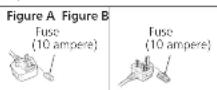
A 10 ampere fuse is fitted in this plug
Should the fuse need to be replaced please ensure that the replacement fuse has a rating of 10 or more and that it is
approved by ASIA or BSI to BSI 362.
Cee for the ASTA mark or the BSI mark in the body
in the fuse. If the plug contains a removable fuse cover you must ensure that it is refilled when the fuse is replaced.
If you see the fuse cover the plug must not be used until a replacement cover is obtained.
A replacement fuse cover can be purchased from your local dealer.
Before use
Remove the connector cover
How to replace the fuse
The location of the fuse differ according to the type of AC
Confirm the AC mains plug fitted and follow the
Instruetioes below.
Illustrations may differ from actual AC mains plug.
1. Open the fuse cover with a screwdriver.
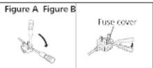
- Replace the fuse and close or attach the fuse cover.

Disposal of Old Equipment Only for European Union and countries with recycling systems
These symbols on the products, packaging, and/or accompanying documents mean that used electrical and electronic products must not be mixed with general household waste.
For proper treatment, recovery and recycling of old products, please take them to applicable collection points in accordance with your national legislation. By disposing of them correctly, you will help to save valuable resources and prevent any potential negative effects on human health and the environment. For more information about collection and recycling, please contact your local municipality. Penalties may be applicable for incorrect disposal of this waste, in accordance with national legislation.
Unit
Do not place sources of naked flames, such as lighted candles, on this unit.
This unit may receive radio interference caused by mobile
If such interference occurs, please increase separation.
between this unit and the mobile telephone.
This unit is intended for use in moderate and tropical
Climate
This unit has some aspects that is on
- Be careful not to catch your hands and/or fingers in the
- Always use two people or more to install or move the
unit.
Placement
- Place this unit on an even surface.
To reduce the risk of fire, electric shock or product damage
Do not install or place this unit in a bookcase, built-in
cabinet or in another continued space. Ensure this unit is well ventilated. - Do not obstruct this unit's ventilation openings with
newspapers, tablecloths, curtains, and similar items. Do not know this unit to direct sunlight, hint.
temperatures, high humidity, and excessive vibration - ensure that the placement location is sturdy enough to
Accumulate the weight of this unit (1) 231. Do not lift or carry this unit by holding the keys
Doing so may cause this unit to fail, resulting in personal injury or malfunction of this unit.
0607
English
IMPORTANT SAFETY INSTRUCTIONS
For the U.S.A. and Canada
Read these operating instructions carefully before using the program. Follow the above instructions as the board shows
the DFT. Finally, the safety instructions on the applicable safety instructions listed below
Keep these operating instructions handy for future
reference.
1 Read these instructions.
2 Keep these insturms in the same place.
3 Reed all warnings. 4 Follow up: inotropic
5 Clean only with dry cloth
- Do not block any ventilation openings. Install in
accordance with the manufacturer's instructions
8 Do not install near any heat sources such as
radiators, heat registers, stoves, or other apparatus (including amplifiers) that produce heat.
- Do not defeat the safety purpose of the polarized
or grounding-type plug. A polarized plug has two
blades with one wider than the other. A grounding type shows that a standard and high quality
plug has two blades and a third grounding plug. The wide blade or the thin prep are provided for your
safety . If the provided input does not fit into your output ,
CNSUII
outlet.
10 Protect the power cord from being walked on or
pinched particularly at plugs, convenience receptacles,
and the point where they exit from the apparatus. 11. Only use attachments/accessories specified by the
12 Use only with the cart, stand.
tripted, bracket, or table specified
by the manufacturer, or sold with
the apparatus. When a cart is used,
use caution when moving the car/ operator repositioning or mud into
apparatus conlution to a 100%
13 Unplug this apparatus during lightning storms or when
unused for long periods of time.
14 Refer all seriog to qualitied service personnel.
Servicing is required when the apparatus has been
damaged in any way, such as power supply cord or shroud or damaged, limbid has been spilled on objects.
plog's damaged, liquid has been spilled or objects have fallen into the容器, the容器 has
been proposed to rain or moisture, does not occur
normally, or has been
Warning
Unit
To reduce the risk of fire, electric shock or product
damage,
Do not expose this unit to rain, moisture, dripping or
splashing.
Do not place objects filled with liquids, such as vases,
on this unit
- Use only the recommended accessories.
-Do not remove covers
-Do not repair this unit by yourself.
Refer servicing to qualified service personnel.
E
中
16
English
IMPORTANT SAFETY INSTRUCTIONS (continued)
For the U.S.A. and Canada
The following mark and symbols are located on the bottom of the unit.

CAUTION
CAUTION
RISK OF ELECTRIC SHOCK
DONOT OPEN

TON
TO REDUCE THE RISK OF ELECTRIC
SHOCK,DO NOT REMOVE SOREWS.
NO USER SERVICEABLE PARTS INSIDE
RETERSERVINGTOQAL

The lightning flash with snowhead symbol within an
equations. In general, it is intended to start the user to themaximum of the initial value "observe a value" within
the products or services that may be classified as
magnify to constitute a risk of electric shock to persons.
The endomotion can with an unergonal curvature
intended to select this user in the presence of impeder
opening and maintenance (servi ng) insur nate in
Conforms to UL STD 62368-1
Certified to CAN/CSA STD C22.2 No.62368-1
THE FOLLOWING APPLIES ONLY IN THE U.S.A. FCC Note:
This equipment has been tested and found to comply with the limits for a Class B digital device, pursuant to Part 15 of the FCC Rules.
These limits are designed to provide reasonable protection
against harmful interference in a residential installation.
This equipment generates, uses and can radiate rad
frequency energy and, if not installed and used in
accordance with the instructions, may cause harmful
interference to radio communications.
However, there is no guarantee that interference will
I not occur in a particular installation. If this equipment
dues cause harmful interference to radin or teilevis
reception, which can be determined by turning theequipment off and on, the user is answered to try to
equipment on and on the user is encouraged to try toconnect the interface by one or more of the following:
correct the interrence by one or more of the following
1
-
Recipient or recipient the receiving antenna.
-
Increase the separation between the equipment and
receiver.
- Connect the equipment into an outlet on a circuit
different from that in which the receiver is connected.
Consult the dealer or an experienced radio TV
technician for help.
ECC Services
To assure continued compliance, follow the attached
installation instructions and use only shielded interface
cables when connecting to peripheral devices.
Any changes or modifications not expressly approved by
the party responsible for compliance could void the user's
This device complies with Part 15 of the FCC Rules.
Operation is subject to the following two conditions:
(1) This device may not cause harmful interference, and
(2) this device must accept any interference recc
including interference that may cause undesired
operation
Responsible Party:
Parasonic Corporation of North America
Toa Barrfrn Plaza,Newark,N07102
Support Contact: http://shop.panasonic.com/support
THE FOLLOWING APPLIES ONLY IN CANADA.
CANICES-3(B)/NMB-3(B)

Information on Disposal in other
Countries outside the European Union
This symbol is only valid in the European
Union
If you wish to discard this product, please
regulate your local authorities or dealer and
ask for the correct method of disposal.
0809
English
Accessories
In order to prevent damage during shipping some of the equipment has been disassembled. Please check and identify the supplied accessories.
AC mains lead (1 pc.) (K2CG3YY00191)
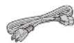
AC mains lead (1 pc) (K2C3MYY00041)
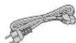
AC mains lead (1 pc.) (K2CSYY00033)

AC mains load (1 pc)
(K2CT3Y00081)

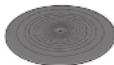
Turntable mat (1 pc.) (RGS0008)
EP record adaptor (1 pc.) (TEKX077)

Screw set for turntable (1 set) (TYL0194)
- Screws-long(3 pc.)
- Washers (3 pc.)
Belleville springs (3 pc.)

Turntable (1 pc.) (TYLO195)

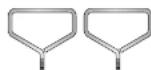
Detachable handle (2 pc) TXQ0020
The model numbers of the accessories are as of February 2018.
They are subject to change without notice.
- Keep the packaging materials after taking out the goods.
You will need them when carrying the product for a long distance.
- Follow the local regulations when disposing of the product.
Do not use any other AC mains lead except the supplied one.
- Keep the auxiliary weight, screws and washers out of reach of children to prevent swallowing.
39
English
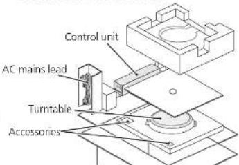
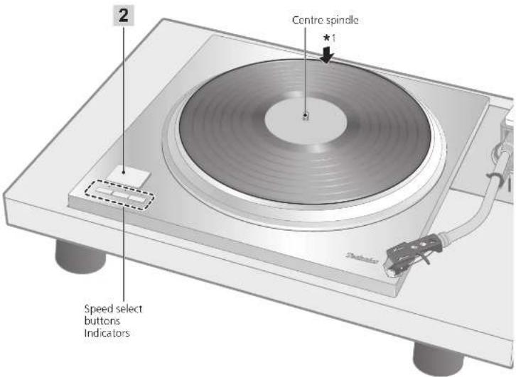
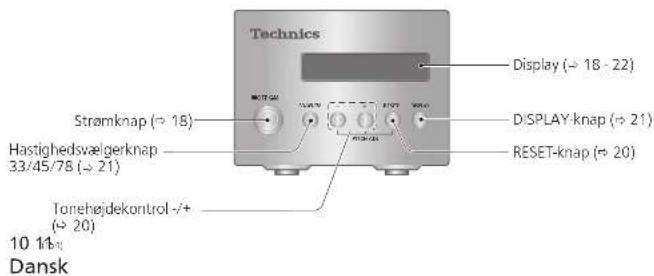
Parts Name
Numbers such as ( 00) indicate reference pages.
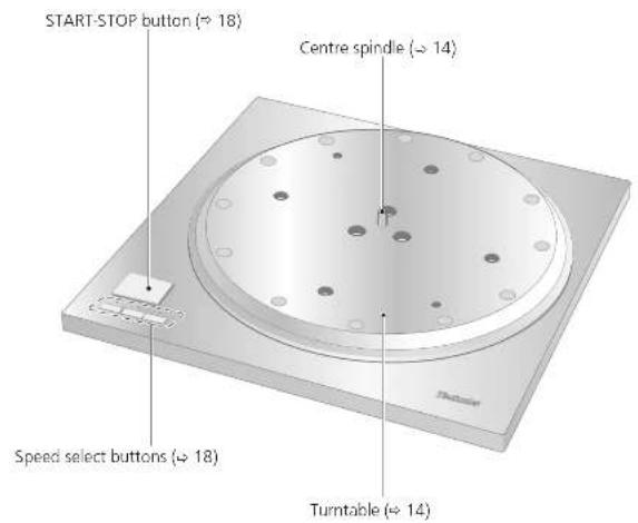
Main unit (Front)
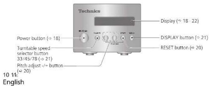
Control unit (Front)
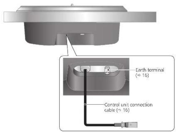
Main unit (Back)
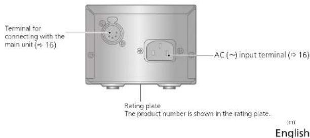
Control unit (Back)
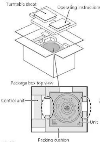
Unpacking and preparation
Notes for taking out the goods from the package box and transporting
Attention
Always use two or more people to take out and transport the main unit.
Be careful not to lose balance if lifting the unit with your hands at non-optimal position. - You may damage your back.
-
You may lose balance on the stairs and the like, which may lead to injury.
-
Be careful not to catch your fingers when taking out the main unit.
- Be careful not to catch your fingers in the gap between the bottom of the main unit and floor.
- Keep the packaging materials after taking out the goods.
Take out the goods after deciding the installation location.
For notes regarding installation, see "Installation" (17).
Take out the turntable sheet and operating instructions.
- Keep accessories out children's reach.
- The main unit and control unit are wrapped in protective sheets.
12 13 English
- Put your hands between the packing cushions (ddotted line area of the package box top view) and slowly lift the main unit to take it out. Always perform this task using two or more people.
- Be very careful when lifting the main unit.
- Hold the main unit from the bottom to prevent it from slipping from your hands.
- Perform the task using both hands to not lose balance.
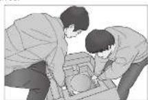
Lifting task image
Take out the control unit, AC mains lead cord, turntable, and other accessories.
Putting the player together
Before putting the player together (Regarding the cabinet and tone arm)
Regarding the cabinet
This player preserves the bottom shape and screw locations of SP-10MK2 and SP-10MK3 so that you can continue using your cabinet and tone-arm for a system using SP-10MK2 or SP-10MK3.
This player is a model with a large starting torque. To make full use of its characteristics and performance, use a heavy cabinet made of a thick material.
When choosing a cabinet, decide its external dimensions based on the effective length of your tone arm.
Use solid and strong insulators to support the cabinet.
- Player mounting dimensions (26)
Regarding the tone arm mounting
- Use the tone arm base sold separately. For details such as the mounting method, follow the tone arm base operating instructions and the tone arm leaflet.
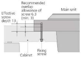
Mounting to the cabinet
1 Tighten the detachable handle screws into the detachable handle mounting holes (two locations) on the main unit.
2 Slowly lift the main unit and place it on the cabinet.
3 Fix the main unit to the cabinet using screws.
- Mount by following the cabinet operating instructions.
Detachable handle mounting hole
引申
English
Putting the player together (continued)
In order to prevent damage during shipping, some of the equipment has been disassembled. Put the player together in the following order.
Attention
- Do not connect the AC mains lead until set up is complete.
- When fitting the turntable, prevent foreign material from getting in between the main unit and turntable.
Attention
- Do not use an electric screwdriver or impact wrench to tighten screws.
- Note that using a screwdriver not fitting to the screws for mounting the turntable may damage the main unit.
14 15
English
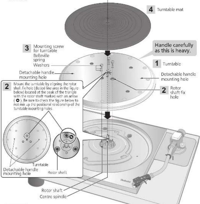
Fitting the turntable

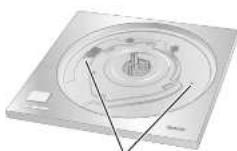
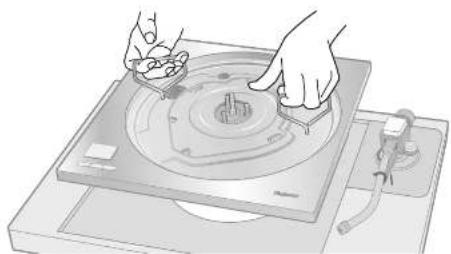
1
Tighten the detachable handle screws into the detachable handle mounting holes (two
locations) on the turntable. Slowly lift the turntable and then lower it in such a way as to insert the center spindle into the hole in the center of the turntable.
Attention
- Tighten the detachable handle by turning it 5 or more times. If you have tightened it until the end, loosen a little bit. Do not tighten it firmly.
- Be careful when handling the turntable, as it is heavy.
- Wipe off fingerprints or dirt with a soft cloth.
2 Slowly lower the turntable while aligning the rotor shaft fix holes (three locations) with the rotor shafts.
- Mount by using the rotor shaft with the arrow mark as a guide. (14)
Attention
- If the rotor shafts are misaligned, a gap remains between the turntable and main unit and you cannot mount the turntable correctly. Do not force the turntable downward.

3
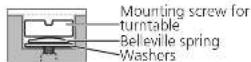
Attach the washers, belleville springs, and screws for turntable to the rotor shaft fix holes, and tighten the mounting screws securely.
4
Attention
- When tightening screws, do not allow screw heads to protrude from the top surface of the turntable.
- Tighten the three screws uniformly. Failing to do so may make the turntable rattle or rotate unstably. Make sure none of the screws are loose.
To remove the turntable
Loosen the mounting screws for turntable and remove them. Keep the screws, belleville springs, and washers carefully.
② Tighten the detachable handle screws into the detachable handle mounting holes (two locations) on the turntable and slowly lift the turntable straight up.
Fitting the turntable mat
Lay the turntable mat on the turntable.
1
English
Connections and installation
- Turn off all units and disconnect the AC power supply cord from the outlet before making any connections.
- Connect the AC power supply cord only after all other connections are completed.
- Refer also to the instruction manual of the connected device.
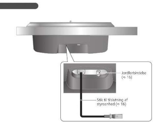
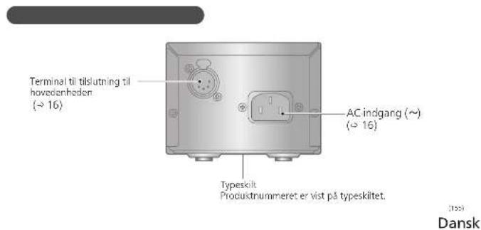
Connecting the control unit / Connecting the power plug and earth ground
1 Connect the control unit connection cable by inserting it until it clicks into place.
2 Connect the AC mains lead.
3 Connect the power plug and earth ground.
- Confirm the wattage of the AC outlet on the connected equipment before using it for this unit. (This unit consumes 10 W.)
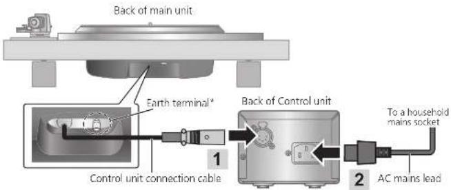
- When necessary, connect the earth terminal of the main unit to that on the amplifier by using a commercially available earth load.
Note
Although the AC power switch is in the "OFF" position, the unit is not completely disconnected from the mains. Remove the plug from the main electrical outlet if you will not be using the unit for an extended period of time. Place the unit so the plug can be easily removed.
Installation
Notes for installation
Always use two people or more to install or move the unit.
Before you move the unit, remove all devices connected and turn off the power supply. Moving the unit with the control unit connected may make it fall off and cause injury.
- Ensure the unit is not exposed to direct sunlight, dust, humidity, and heat from a heating appliance.
- This unit may pick up interference from a radio if there is one nearby. Keep the unit as far as possible from a radio.
- Do not install the unit on a heat source.
- Avoid a place with large temperature variations.
- Avoid a place with frequent condensation.
- If anti-tip measures are required, consult a contractor. The floor and wall strength need to be checked.
- Avoid an unstable place.
- Do not put an object on the unit.
- Do not install the unit in a confined space such as a book shelf.
- Install the unit at a position well away from walls or other devices to ensure effective heat radiation from the inside of the unit.
- Make sure the installation location is sufficiently strong to withstand the total weight of the unit and system.
Note that the unit may be damaged by cigarette smoke or moisture from an ultrasonic humidifier.
Condensation
Think of taking out a cold bottle from a refrigerator. If you leave it in a room for a while, dewdrops will form on the bottle surface.
This phenomenon is called "condensation".
- Conditions causing condensation
Rapid temperature change (caused by moving from a warm place to a cold place or vice versa, rapid cooling or heating, or direct exposure to cooled air).
High humidity in a room with much steam, ctc.
Rainy season
- Condensation may damage the unit. If it has occurred, turn the unit off and leave it until it adapts to the ambient temperature (approximately 2 to 3 hours).
1617
English
16
English
Playing records
Preparation
1 Put a record (not included) on the turntable.
Attention
Do not press [START-STOP] when the turntable is removed.
18 19
English
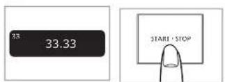
2 Press [START-STOP]. The turntable starts revolving.
When play finishes
① Lift the cue lever, return the tone arm to the arm rest and lower the cue lever.
密 Process [START-STOP]
The electronic brake gently stops the
turntable
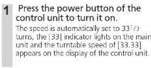
Press the power button of the control unit to turn it off.
Clamp the tone arm with the arm clamp.
Put the stylus cover back on (to protect the stylus lip).
When playing EP records
Press the speed select button [45].
(145) lights.
- Fit the EP record adaptor over the centre spindle.
When playing SP records
Press the speed select button [78] ([78] lights).
When using a record stabilizer (not included)
See the instruction manual of the record stabilizer.
Maximum weight: 1 kg
Note
- Pressing [33/45/78] on the control unit can also change the turntable speed. (≈ 21)

English
Pitch control (fine adjustment to pitch)
1 Press [-] or [+] on the control unit to make adjustment.
The pitch can be set within approximately ± 16% of the currently set turntable speed [33/45/78].
- The current set value appears on the display of the control unit. The display differs depending on the display mode.
(Switching the display mode 21
The turntable speed changes each time the pitch is set while the turntable is rotating.
*Pressing the button increases or decreases the value.
*Holding the button down accelerates the increase or decrease.
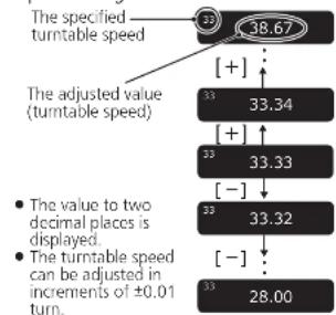
- When the display mode is "Turntable speed setting"
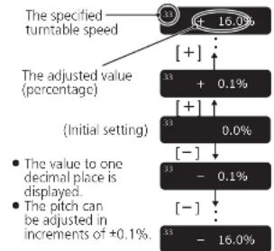
When the display mode is "Pitch setting"
20 21:
English
To return to the prescribed turntable speed Press [RESET] on the control unit.
The value immediately returns to the prescribed turntable speed. (31/3, 45 or 78.26 rpm)
- The display of the control unit shows the prescribed setting.
The turntable speed becomes the prescribed turntable speed in the turntable speed setting mode and 0.0% in the pitch setting mode.
(Display mode: Turntable speed setting)

Speed selector button indicators of the main unit during pitch control
Blue LED on: Without pitch control (0.0%)
Orange LED on: During pitch control
Note
- The pitch can be set for each turntable speed.
- Turning off the power button cancels the pitch control setting. Turning on the power button again returns the value to the initial setting.
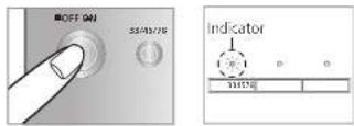
Operation and display of the control unit
Turntable speed setting
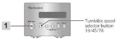
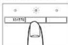
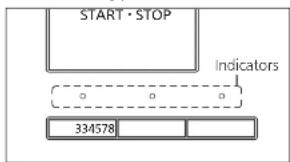
1 Press [33/45/78] on the control unit.
Each time [33/45/78] is pressed, the turntable speed changes in order of "33" → "45" → "78" → "33" → ...
The turntable speed changes each time the pitch is set while the turntable is rotating.
![TECHNICS SP10RE - Press [33/45/78] on the control unit. - 1](/content/2026/03/466661/images/153755777de5ea69c30e613224b90d04d5052792980ea9ea89fff8e8774c8304.jpg)
Switching the display mode
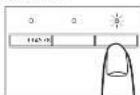
Press [DISPLAY] on the control unit.
Each time [DISPLAY] is pressed, the display mode changes in order of "turntable speed setting" "Pitch setting" "Turntable speed measurement" "Turntable speed setting" ...
![TECHNICS SP10RE - Press [DISPLAY] on the control unit. - 1](/content/2026/03/466661/images/84c161cebea21a357ae8d3628b759eb0b474d3c0cc0be5e15b058fc9ab8f4086.jpg)
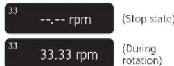
Turntable speed measurement
The actual turntable speed can be measured in this display mode. Switch the display mode (see above) to enter this mode.
- "rpm" appears after the numerical value.
- "... rpm" appears when the turntable has stopped.
Operation during "Turntable speed measurement"
Operating the buttons as below changes the display mode to "Turntable speed setting" allowing you to make the setting. The display mode returns to "Turntable speed measurement" if no operation is performed within three seconds.
- [ [-] / [-] ] : The pitch can be adjusted.
- [ 20 ] :
- RESET: The value immediately returns
the prescribed turntable speed. [33/45/78]: The turntable speed changes each time the button is pressed.
Note
An averaged value is displayed.
[21]
English
Operation and display of the control unit (continued)
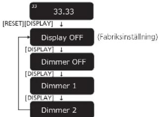
Display dimmer setting
The display dimmer will be activated if the control unit is not operated for 20 seconds. There are four dimming patterns.
1 On the control unit, hold [RESET] down and press [DISPLAY].
The dimmer setting is displayed.
2 Press [DISPLAY] on the control unit. The setting changes each time [DISPLAY] is pressed. (+)See below.)
- The display returns to the original display if no operation is performed within three seconds.

| Display | Display dimmer when no operation is performed for 20 seconds |
| Display OFF | Brightness is reduced by one level. →(No operation for further five seconds) →Brightness is reduced by two levels. →(No operation for further five seconds) →Off |
| Dimmer OFF | No dimming (Always on) |
| Dimmer 1 | Brightness is reduced by one level. |
| Dimmer 2 | Brightness is reduced by two levels. |
After setting, brightness is immediately adjusted to the set value. The display is immediately turned off if "Display OFF" is selected.
- Operating a button (any button other than the power button) on the control unit while the dimmer is active returns the display to full brightness.
Note
- The setting is saved. When the power is turned on the next time, the setting when the power was turned off will be recovered.
22 22
English
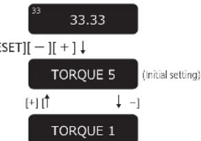
Adjusting the torque to rotate the turntable at a constant speed
Press [START-STOP] and then adjust the torque (rotational force) at five levels to rotate the turntable at a constant speed.
1 On the control unit, hold [RESET] down and press [-] and [+] simultaneously.
The torque setting is displayed.
2 Press [-] or [+] on the control unit to make adjustment.
- Select one of the five levels from "TORQUE1" to "TORQUES". Pressing the button increases or decreases the value.
- Use the table below as a guide.
- The display returns to the original display if no operation is performed within three seconds.
| Display | Torque to rotate at a constant speed |
| TORQUE5 Maximum (Initial setting) | |
| TORQUE4 | |
| TORQUE3 | |
| TORQUE2 | |
| TORQUE1 Minimum | |
Note
- The setting is saved. When the power is turned on the next time, the setting when the power was turned off last will be recovered.
Maintenance
Cleaning the main unit
Wipe the main unit and other components with a dry soft cloth.
When dirt is heavy, wring a wet cloth tightly to wipe the dirt, and then wipe it with a soft cloth. Do not use solvents including benzene.
bo not use solvents including benzene, thinner, alcohol, kritchen detergent, a
chemical wiorr, stc. This might cause the
exterior case to be deformed or the coating to come off.
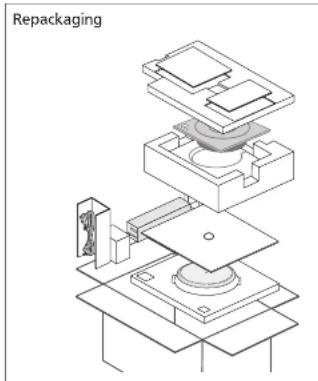
Moving the unit
Repackage the unit in the packaging it came in. ( 12)
Keep the packaging materials after taking out the goods.
If you no longer have the packaging, do the following:
- Take off the turntable and turntable mat and carefully wrap them.
- Carefully wrap the main unit in a blanket or paper.
WEEE symbol
Disposal of the product outside the EU countries
This symbol is valid within the EU only. Contact a local governmental office or your dealer to confirm a right manner of disposal.
23
English
Troubleshooting guide Specifications
Before requesting service, make the below checks. If you are in doubt about some of the check points, or if the remedies indicated in the chart do not solve the problem, contact your dealer.
No power
Is the AC mains load plugged in?
Plug the mains lead in firmly. (一 16)
- Is the control unit connected with the main unit?
Insert the control unit connection cable until it clicks. ( 16)
No indication on the display of the control unit
- Is the power plug connected?
- Insert it firmly. (→16)
Is the power on? Press the power button to turn on the power. (18)
Is the display dimmer activated? Operate a button (any button other than the power button) on the control unit. (一 22)
■ Error code
Occurrence of an error will be notified as necessary on the display of the control unit and with the speed selector button indicators of the main unit.
| Display of the control unit | Measure |
| Unconnected | Check that the control unit is connected with the main unit. (→16) |
| F58 | Consult your dealer. |
| F76 | One of the [33/45/78] speed selector button indicators of the main unit blinks (rapidly or slowly) in orange. |
| F17 | Provide the displayed number and the LED's blinking status at the time of consultation. |
Example of the display of the control unit in case of an error
Unconnected
Example of the speed selector button indicators of the main unit in case of an error) Flashes in orange.
| 3345 | 78 |
| General | |
| Power supply AC 110-240 V, 50/60 Hz | |
| Power consumption 10 W (Power ON) | |
| 0.05 W (Power OFF) | |
| Dimensions(W×H×D) | <Control unit>110×84×350 mm (4-11/32×3-5/16×13-25/32 inch) |
| <Main unit>365×109×365 mm (14-3/8×4-3/6×14-3/8 inch) | |
| Mass <Control unit> | Approx. 2.1 kg (4.7 lbs) |
| <Main unit>Approx. 18.2 kg (40.2 lbs) | |
| Operatingtemperature range | 0 °C to 40 °C(32 °F to 104 °F) |
| Operating humidity range 35 %to 80 % RH(no condensation) | |
| Turntable section | |
| Drive method Direct drive | |
| Motor Brushless DC motor | |
| Turntable Brass and Aluminum | die-cast combinedDiameter: 323 mm (12-23/32 inch)Mass: Approx. 7.9 kg (17.5 lbs)(including the turntable sheet) |
| Turntable speeds 33-1/3, 45 and78* rpm | |
| Variable range pitch ±16 % | |
| Starting torque 0.39 N·m (4.0 k g·cm)/3.47 lb·in | |
| Braking system Electronic brake | |
| Wow and flutter 0.015 % W.R.M.S.(JIS C5521) | |
| Terminal section | |
| Output terminal Earth terminal | |
Specifications are subject to change without notice.
The turntable speed will be 78.26 rpm when set to 78 rpm (pitch control 0.0%).
Dimensional drawings
External dimensions
Select a cabinet that fits with the external dimensions of the player.
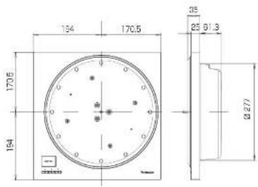
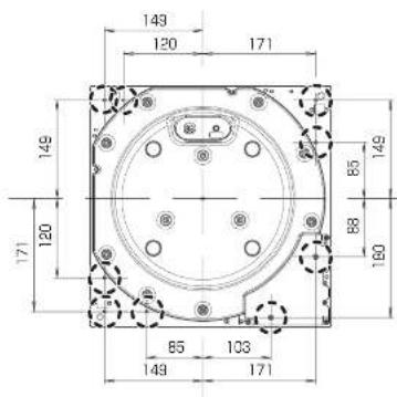
- Locations of the screws for fixing the cabinet
Fix the player to the cabinet at the nine positions (marked with dotted line) shown in the right figure (the bottom surface of the main unit).
26 27
English
27 English
IMPORTANT MISES EN GARDE
The applicable (see emplacements)
Raccordements et installation
Section tourne-disque
enewestiesCarder.org
Raccordements et installation
c consequent lscioni personal o

In order to prevent damage during shipping some of the equipment has been disassembled. Please check and identify the supplied accessories.
Styreened (forside) Styreenhe
(331/3,45 ether 78,26 rpm)
* Styrenehedens display viser
1ds 120 secondersins fura dimmon
1 Pa styrenheten haller du [Aterstall] nere och trycker pa [DISPLAY].
- Installingen for dimmern visas.
2 Tryck pa [Display] pa styrenheten.
Instiltingen andras varje gang du trycker pa DISPLAY.
- Vissningsljet atergär till den ursprungjagyn om ingen operation utfers inom tsekundar.
| Skärm | Visningsdimmer narr ingen operation ufför s 20 sekunder |
| Display OFF | Ljusstyrian reduceras med en niva ⇒ (ingen operation i yterligare fem sekunder) Ljusstyrian reduceras med tv nivd. ⇒ (ingen operation i yterligare fem sekunder) ⇒ Av |
| Dimmer OFF | Ingen dimmer (Alltid på) |
| Dimmer 1 | Ljusstyrian reduceras med en niva |
| Dimmer 2 | Ljusstyrian reduceras med tv nivd. |
- After installing justeras liusstykran omedelbar
hil det installdia vandet. Display displays aned
medelbarorn "Display Av" ar valid. - Anwandring avn knapp (nagán annan knapp àn ströbtryanten) på kontrottenhemed mediammern àraktiv,äterställer skärmén till fuljussyrka.
Observera
Limited Warranty (ONLY FOR U.S.A.)
Technics Products - Limited Warranty
Limited Warranty Coverage (For USA Only)
If your product does not work properly because of a defect, in the event of working manually, Parascoic Corporation of North America is referred to as "the warrantor" well, for the extent of the period indicated on the chart below, which means with the date of original purchase ("warranty period"), as its option either (a) repair your product with new or refurnished parts, (b) replace it with a new or a refined equivalent value product, or (c) refund your purchase price. The decision to repair, replace or refund will be made by the warrantor.
| Product or Part Name Parts Label | ||
| Technics Network Audio Amplifier | 3 (three) years | 3 (three) years |
| Technics Music Server | ||
| Technics CD Steer System | ||
| Technics Turntable System | ||
During the "Latory" warranty period there will be no charge for labor. During the "Parts" warranty period, there will be no charge for parts. This Limited Warranty excludes both parts one labor for non-rechargeable batteries, antennas, and coaxic parts (cabinet). This warranty only applies to products purchased and serviced in the United States. This warranty is extended only to the original purchaser of a new product which was not sold "as such." Mail in Service-Online Result Request
Online Renew Request
To submit a new repair request and for quick repair status within our Web site at:
http://shop.patanotic.com/support
When shipping the unit, there's plenty slack, incl. all supplied accessories failed in the Owner's Manual, etc. send it present, adequately insured and paided well in a certain box. When shipping Lithium for batteries please visit our Web site at http://shipspeedhenomonic.com/support/Finemax is committed to delivering the highest quality of lithium-ion batteries available. Write a letter to the complaint, a return address and provide a daytime phone number where you can be contacted. A visit registered receipt is required under the Limited Warranty.
IF REPAIR IS NEEDED DURING THE WARRANTY PERIOD, THE PURCHASER WILL BE REQUIRED TO FURNISH A SALES. RECEIPT/PROOF OF PURCHASE INDICATING DATE OF PURCHASE, AMOUNT PAID AND PLACE OF PURCHASE CUSTOMER WILL BE CHARGED FOR THE REPAIR OF ANY UNIT RECEIVED WITHOUT SUCH PROOF OF PURCHASE.
Limited Warranty Limits and Exclusions
This company DAILY COVER DETAILS: Failure to cover items in materials or workmanship, and DOTS NOT COVER: annual wear and tear or cosmetic damage. The warranty also DOES NOT COVER damages which occurred in shipment, or failures which are caused by products not supplied by the warranty, or failures which result from contents, prices, amounts, neglect, misordering, mispositioning, alteration, faulty installation, setup adjustments, misappropriation of consumer control, improper maintenance, power line surge, lighting damage, modification, introduction of sand, humidity or fluids; commercial use such as hotel, office, restaurant, or other business or premises of the premises or persons by anyone other than a factory Service Center or other Authorized Service center, or damage that is attributable to acts of God.
| Model number and serial number of this product can be found on either the back or the bottom of the unit. Please note them in the space provided below and keep for future reference. |
| MODEL NUMBER | SP-10R |
| SERIAL NUMBER |
THERE ARE NO EXPRESS WARRANTYORIES EXCEPT AS LISTED UNDER "LIMITED WARRANTY COVERAGE"
THE WARRANTYORIS NOT LIABLE FOR INCIDENTAL OR CONSEQUENTIAL DAMAGES RESULTING FROM THE USE OF THIS PRODUCT, OR ASRIING OUT OF ANY REFRESH OF THIS WARRANTY.
[As examples, this excludes damages for lost time, travel etc. and from the service, loss of or damage to media or images, data or other memory or recorded contents. The items listed are not exclusive, but for illustration only.]
ALL EXPRESS AND IMPLIED WARRANTY, INC. LIMITED: THE WARRANTY OF MERCHANTIBILITY, ARE LIMITED TO THE FOLLOWING TERMS:
Some states do not allow the exclusive or limitation of incidental or consequential damages, or limitations on how long an implied warranty lasts; so the exclusions may not apply to you. This warranty gives you specific legal rights and you may also have other rights which vary from state to state. If a problem with this product develops during or after the warranty period, you may contact your dealer or Service Center. If the problem is not handled by your salesperson, then write to:
Consumer Affairs Department
Parasonic Corporation of North America
561 Independence Plan
Chassapake,VA 23320
PARTS AND SERVICE, WHICH ARE NOT COVERED BY THIS LIMITED WARRANTY, ARE YOUR RESPONSIBILITY.
Shop
Accessories!
for all your Technics gear
Go to
http://shoeparssnacr.com/support
Ge, everything you need to get the most out of your brands products
Accessories & Parts for your Camera, Phone, A/V introduces, TV, Computers & Networking, Personal Care, Home Appliances, Fitness Machines, Batteries, Breakfast Chackers & more...
Customer Services Directory
For Product Information, Operating Assistance, and Technical Support, please visit http://www.cisco.com/support.
For the hearing or speech-impaired ITV, 877-833-8859
As of February 2018
User memo:
| DATE OF PURCHASE |
| DEALER NAME |
| DEALER ADDRESS |
| TELEPHONE NUMBER |
Limited Warranty (ONLY FOR CANADA)
Panasonic Canada Inc.
5770 Ambler Drive, Mississauga, Ontario L4W 2T3
TECHNICS PRODUCT - LIMITED WARRANTY
Panasonic Canada Inc. warrants this product to be free from defects in material and workmanship under normal use and for a period as stated below from the date of original purchase agrees In, at its option either (a) repair your product with new or refurbished parts, (b) replace it with a new or a refurbished equivalent value product, or (c) refund your purchase price. The decision to repair, replace or refund will be made by Panasonic Canada Inc.
| Technics Network Audio Amplifier 3 (three) years parts and labour |
| Technics Music Server 3 (three) years parts and labour |
| Technics CD Stereo System 3 (three) years parts and labour |
| Technics Turnable System 3 (three) years parts and labour |
This warranty is given only to the original purchaser, or the person for whom it was purchased as a gift, of a Technics brand product mentioned above sold by an authorized Panasonic dealer in Canada and purchased and used in Canada, which product was not sold "as is", and which product was delivered to you in new condition in the original packaging.
IN ORDER TO BE ELIGIBLE TO RECEIVE WARRANTY SERVICE HEREUNDER, A PURCHASE RECEIPT OR OTHER PROOF OF DATE OF ORIGINAL PURCHASE, SHOWING AMOUNT PAID AND PLACE OF PURCHASE IS REQUIRED
LIMITATIONS AND EXCLUSIONS
This warranty ONLY COVERS failures due to defects in materials or workmanship, and DOES NOT COVER normal wear and tear or cosmetic damage. The warranty ALSO DOLS NOT COVLR damages which occurred in shipment, or failures which are caused by products not supplied by Panasonic Canada Inc., or failures which result from accidents, misuse, abuse, neglect, mishandling, misapplication, alteration, faulty installation, set up adjustments, misadjustment of consumer controls, improper maintenance, power line surge, lightning damage, modification, introduction of sand, humidity or liquids, commercial use such as hotel, office, restaurant, or other business or rental use of the product, or service by anyone other than an Authorized Servicer, or damage that is attributable to acts of God.
Dry cell batteries are also excluded from coverage under this warranty.
THIS EXPRESS, LIMITED WARRANTY IS IN LEU OF ALL OTHER WARRANTYIS, EXPRESS OR IMplied, INCLUDING ANY IMPLIED WARRANTY OF MERCHANT ABILITIES AND FITNESS FOR A PARTICULAR PURPOSE IN NO EVENT WILL PANASONIC CANADA INC. BE LIABLE FOR ANY SPECIAL, INDIRECT OR CONSEQUENTAL DAMAGES RESULTING FROM THE USE OF THIS PRODUCT OR ASRISING OUT OF ANY BREACH OF ANY EXPRESS OR IMplied WARRANTY. (As examples, this warranty excludes damages for lost time, travel to and from the Authorised Seller, loss of or damage to media or images, date or other memory or recorded content. This list of items is not exhaustive, but for illustration only.)
In certain instances, some jurisdictions do not allow the exclusion or limitation of incidental or consequential damages, or the exclusion of implied warranties, so the above limitations and exclusions may not be applicable. This warranty gives you specific legal rights and you may have other rights which vary depending on your province or territory.
WARRANTY SERVICE
For product operation, repairs and information assistance, please visit our Support page on
www.eanasonic.ca/english/support
IF YOU SHIP THE PRODUCT TO A SERVICENTRE
Carefully pack and send prepaid, adequately insured and preferably in the original carton.
Include details of the defect claimed, and proof of date of original purchase.
图2-1
English
Certificat de garantie limite (SEULEMENT POUR LE CANADA)
Panasonic Canada Inc.
5770, Ambler Drive, Mississauga (Ontario) L4W 2T3
PRODUIT TECHNICS - GARANTIE LIMITEE


- For the U.S.A.
- For Canada / Pour le Canada
- For the United Kingdom and Ireland
- For Continental Europe
- SP-10R
- Delivering the Ultimate Emotive Musical Experience to All
- For the U.S.A. and Canada
- For the United Kingdom and Ireland customers
- Features
- Coreless direct drive motor for smooth and accurate rotation
- Three-layer turntable for stable rotation
- Special control unit that can eliminate unwanted noise interference with the main unit
- Compatibility with SP-10MK2 and SP-10MK3
- Table of contentsIntroduction
- Before use
- Getting started
- Playing back
- Maintenance
- Safety precautions
- Warning
- Unit
- AC mains lead
- Caution for AC Mains Lead
- How to replace the fuse
- Disposal of Old Equipment Only for European Union and countries with recycling systems
- Placement
- 0607
- English
- IMPORTANT SAFETY INSTRUCTIONS
- IMPORTANT SAFETY INSTRUCTIONS (continued)
- CAUTION
- THE FOLLOWING APPLIES ONLY IN THE U.S.A. FCC Note:
- THE FOLLOWING APPLIES ONLY IN CANADA.
- CANICES-3(B)/NMB-3(B)
- Accessories
- Parts Name
- Unpacking and preparation
- Notes for taking out the goods from the package box and transporting
- Attention
- Putting the player together
- Before putting the player together (Regarding the cabinet and tone arm)
- Regarding the cabinet
- Regarding the tone arm mounting
- Mounting to the cabinet
- Putting the player together (continued)
- Fitting the turntable
- To remove the turntable
- Fitting the turntable mat
- Connections and installation
- Connecting the control unit / Connecting the power plug and earth ground
- Note
- Installation
- Notes for installation
- Condensation
- Playing records
- Preparation
- When play finishes
- When playing EP records
- When playing SP records
- When using a record stabilizer (not included)
- Pitch control (fine adjustment to pitch)
- Operation and display of the control unit
- Turntable speed setting
- Press [33/45/78] on the control unit.
- Switching the display mode
- Press [DISPLAY] on the control unit.
- Turntable speed measurement
- Operation and display of the control unit (continued)
- Display dimmer setting
- 22
- Adjusting the torque to rotate the turntable at a constant speed
- Cleaning the main unit
- Moving the unit
- WEEE symbol
- Troubleshooting guide Specifications
- No power
- No indication on the display of the control unit
- ■ Error code
- Unconnected
- Dimensional drawings
- External dimensions
- - Locations of the screws for fixing the cabinet
- IMPORTANT MISES EN GARDE
- Raccordements et installation
- Observera
- Limited Warranty (ONLY FOR U.S.A.)
- Technics Products - Limited Warranty
- Limited Warranty Coverage (For USA Only)
- Online Renew Request
- http://shop.patanotic.com/support
- Limited Warranty Limits and Exclusions
- Shop
- Accessories!
- User memo:
- Limited Warranty (ONLY FOR CANADA)
- TECHNICS PRODUCT - LIMITED WARRANTY
- LIMITATIONS AND EXCLUSIONS
- WARRANTY SERVICE
- Certificat de garantie limite (SEULEMENT POUR LE CANADA)
- PRODUIT TECHNICS - GARANTIE LIMITEE
Brand : TECHNICS
Model : SP10RE
Category : Turntable