
XMGS4 - Car speaker SONY - Free user manual and instructions
Find the device manual for free XMGS4 SONY in PDF.
| Product Type | Power amplifier for car speaker |
| Brand | Sony |
| Model | XMGS4 |
| Dimensions (W x H x D) | Approx. 272 x 51 x 202 mm |
| Power Supply | 12 V DC (negative ground), range 10.5 - 16 V |
| Maximum Power | 150 W x 4 (at 4 Ω) or 350 W x 2 (bridged, at 4 Ω) |
| Rated Power (14.4 V, 1% THD) | 80 W x 4 (2 Ω), 70 W x 4 (4 Ω), 160 W x 2 (4 Ω bridged) |
| Speaker Impedance | 2 - 8 Ω (stereo), 4 - 8 Ω (bridged) |
| Frequency Response | 10 Hz - 100 kHz (+0.5 dB) |
| Total Harmonic Distortion | ≤ 0.05% (at 1 kHz, 4 Ω) |
| Built-in Filters | Low-pass (50 - 300 Hz), high-pass (50 - 300 Hz), subsonic (6 - 70 Hz), bass boost (40 Hz, +10 dB max) |
| Inputs | RCA jacks (0.3 - 6 V) and high-level input connector (3 - 12 V) |
| Current Consumption | 33 A (at rated power, 4 Ω, 70 W x 4) |
| Protection | Protection circuit against overheating, short circuit, DC; white LED (on) / red LED (protection) |
| Recommended Installation | Trunk or under a seat, do not obstruct ventilation, avoid direct sun and heat exposure |
| Maintenance | Fuse replacement (60 A) - use a fuse of same amperage |
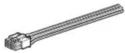
| Supplied Accessories | High-level input cord (1), mounting screws (4) |
| General Information | Made in Thailand; EU importer: Sony Europe B.V., Belgium |
Frequently Asked Questions - XMGS4 SONY
User questions about XMGS4 SONY
0 question about this device. Answer the ones you know or ask your own.
Ask a new question about this device
Download the instructions for your Car speaker in PDF format for free! Find your manual XMGS4 - SONY and take your electronic device back in hand. On this page are published all the documents necessary for the use of your device. XMGS4 by SONY.
USER MANUAL XMGS4 SONY
Stereo Power Amplifier
Усилитель
Стерео підсилювач
| Operating Instructions | GB |
| Mode d'emploi | FR |
| Manual de instrucciones | ES |
| Bedienungsanleitung | DE |
| Istruzioni per l'uso | IT |
| Gebruiksaanwijzing | NL |
| Bruksanvisning | SE |
| Instruções de operação | PT |
| Instrukcja obsługi | PL |
| Инструкция по эксплуатации | RU |
| Инструкції з експлуатації | UA |
| คู่มือแนะนําการใช้งาน | TH |
| 使用説明書 | CT |
Owner's Record
The model and serial numbers are located on the bottom of the unit. Record the serial number in the space provided below.
Refer to these numbers whenever you call upon your Sony dealer regarding this product.
Model No. XM-GS4
Serial No. ____

For safety, be sure to install this unit either inside the trunk (boot) or under a seat. For details, see "Installation and Connections" (page 5).
Made in Thailand
Notice for customers: the following information is only applicable to equipment sold in countries applying EU Directives
This product has been manufactured by or on behalf of Sony Corporation.
EU Importer: Sony Europe B.V.
Inquiries to the EU Importer or related to product compliance in Europe should be sent to the manufacturer's authorized representative, Sony Belgium, bijkantoor van Sony Europe B.V., Da Vincilaan 7-D1, 1930 Zaventem, Belgium.

Disposal of waste batteries and electrical and electronic equipment (applicable in the European Union and other European countries with separate collection systems)
This symbol on the product, the battery or on the packaging indicates that the product and the battery shall not be treated as household waste. On certain batteries this symbol might be used in combination with a chemical symbol. The chemical symbols for mercury (Hg) or lead (Pb) are added if the battery contains more than 0.0005% mercury or 0.004% lead.
By ensuring these products and batteries are disposed of correctly, you will help prevent potentially negative consequences for the environment and human health which could otherwise be caused by inappropriate waste handling. The recycling of the materials will help to conserve natural resources.
In case of products that for safety, performance or data integrity reasons require a permanent connection with an incorporated battery, this battery should be replaced by qualified service staff only.
To ensure that the battery and the electrical and electronic equipment will be treated properly, hand over these products at end-of-life to the applicable collection point for the recycling of electrical and electronic equipment.
For all other batteries, please view the section on how to remove the battery from the product safely. Hand the battery over to the applicable collection point for the recycling of waste batteries.
For more detailed information about recycling of this product or battery, please contact your local Civic Office, your household waste disposal service or the shop where you purchased the product or battery.

This symbol is intended to alert the user to the presence of a hot surface. The symbol applies to Europe models only.
If you have any questions or problems concerning your unit that are not covered in this manual, please consult your nearest Sony dealer.
Features
• Maximum power output of 150 W per channel (at 4 Ω).
- This unit can be used as a bridging amplifier with a maximum output of 350 W.
- Built-in LP (low-pass) filter, HP (high-pass) filter, subsonic filter and Low boost circuit.
• Protection circuit and indicator provided.
- Direct connection can be made with the speaker output of your car audio unit if it is not equipped with the line output (High level input connection).
- Hi-level Sensing Power On feature allows this unit to be activated without the need for REMOTE connection.
- Pulse power supply* for stable and regulated output power.
* Pulse power supply
This unit has a built-in power regulator which converts the power supplied by the 12 V DC car battery into high speed pulses using a semiconductor switch. These pulses are stepped up by the built-in pulse transformer and separated into both positive and negative power supplies before being converted into direct current again. This is to regulate fluctuating voltage from the car battery. This lightweight power supply system provides a highly efficient power supply with a low impedance output.
Table of Contents
Features 3
Operation
Location and Function of Controls .... 4
Installation and Connections
Parts for Installation and Connections.....5
Installation 5
Connections 5
Power Connections 5
Input Connections 6
Speaker Connections 7
Additional Information
Precautions 9
Maintenance 9
Fuse Replacement....9
Specifications....10
Troubleshooting 11
Operation
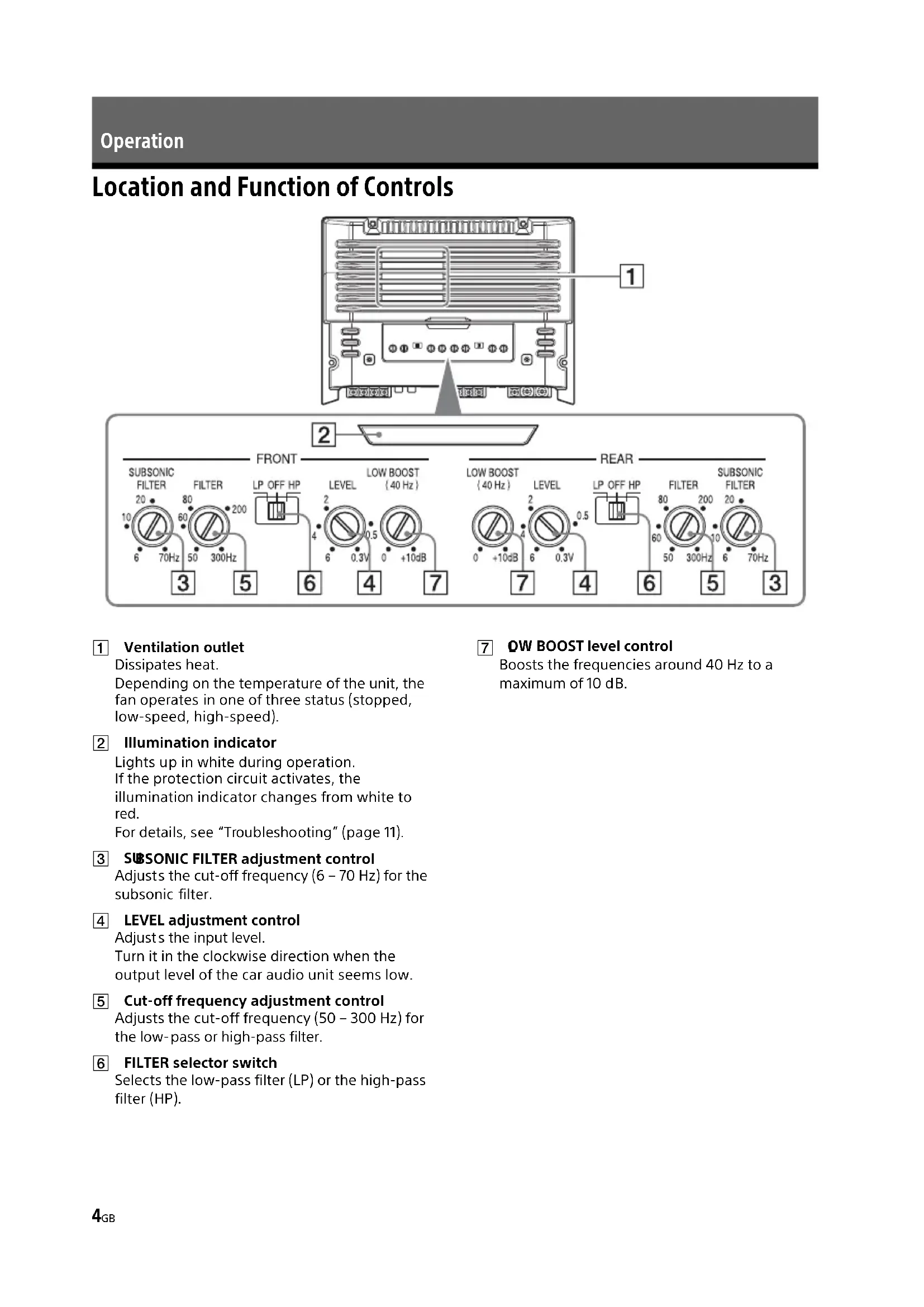
Location and Function of Controls
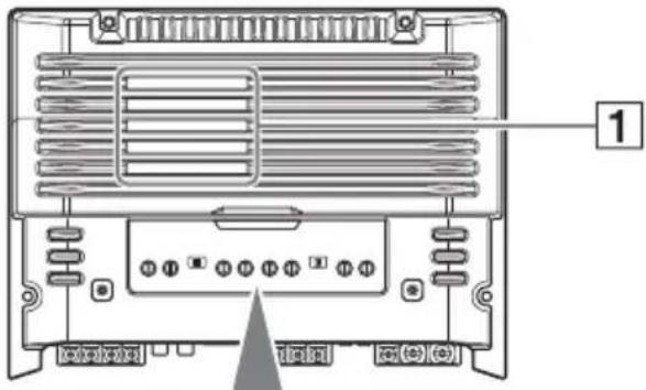

1 Ventilation outlet
Dissipates heat.
Depending on the temperature of the unit, the fan operates in one of three status (stopped, low-speed, high-speed).
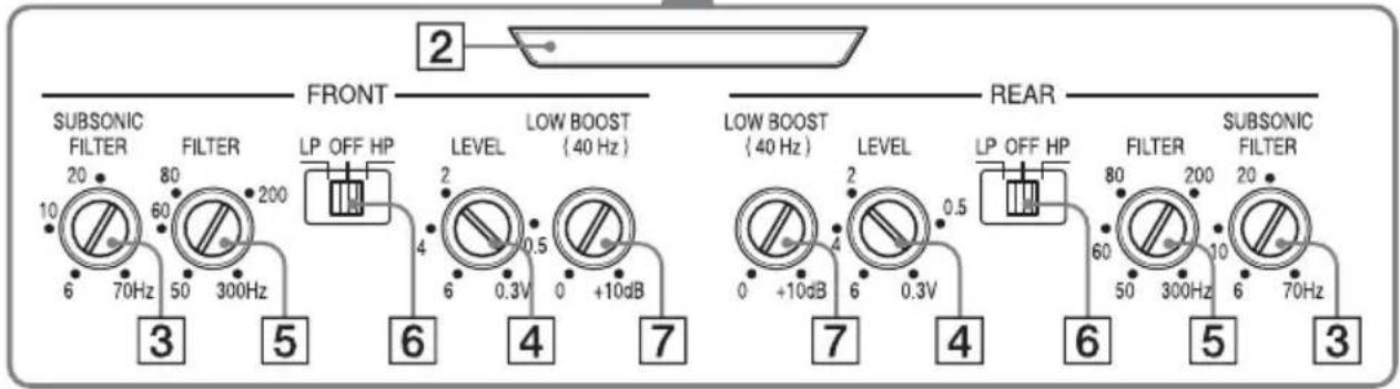
2 Illumination indicator
Lights up in white during operation.
If the protection circuit activates, the
illumination indicator changes from white to red.
For details, see "Troubleshooting" (page 11).
3 SUBSONIC FILTER adjustment control
Adjusts the cut-off frequency (6 - 70 Hz) for the subsonic filter.
4 LEVEL adjustment control
Adjusts the input level.
Turn it in the clockwise direction when the output level of the car audio unit seems low.
5 Cut-off frequency adjustment control
Adjusts the cut-off frequency (50 - 300 Hz) for the low-pass or high-pass filter.
6 FILTER selector switch
Selects the low-pass filter (LP) or the high-pass filter (HP).
7 QW BOOST level control
Boosts the frequencies around 40 Hz to a maximum of 10 dB.
Installation and Connections
Parts for Installation and Connections
①
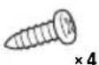
4 × 14 mm (3/16 × 9/16 in)
②
This parts list does not include all the package contents.
Installation
- Mount the unit either inside the trunk (boot) or under a seat.
- Choose the mounting location carefully so the unit will not interfere with the normal movements of the driver and it will not be exposed to direct sunlight or hot air from the heater.
- Do no install the unit under the floor carpet, where the heat dissipation from the unit will be considerably impaired.
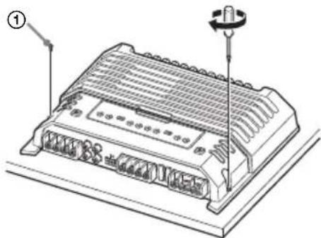
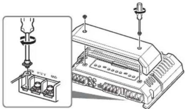
Mounting the unit
First, place the unit where you plan to install it, and mark the positions of the 4 screw holes on the mounting board (not supplied). Then drill a 3 mm (1/8 in) pilot hole at each mark and mount the unit onto the board with the supplied mounting screws. The mounting screws are all 14 mm (9/16 in) long, so make sure that the mounting board is thicker than 14 mm (9/16 in).
natural_image
Technical line drawing of a mechanical device with a screw and housing (no text or symbols)Connections
- Before making any connections, disconnect the ground (earth) terminal of the car battery to avoid short circuits.
- Be sure to use speakers with an adequate power rating. If you use small capacity speakers, they may be damaged.
• This is a Phase-Inverted Amplifier. - Do not connect the ⊖ terminal of the speaker system to the car chassis, and do not connect the ⊖ terminal of the right speaker with that of the left speaker.
• Install the input and output cords away from the power supply wire. Running them close together may generate interference noise. - This unit is a high powered amplifier. Therefore, it may not perform to its full potential if used with the speaker cords supplied with the car.
- If your car is equipped with a computer system for navigation or some other purpose, do not remove the ground (earth) wire from the car battery. If you disconnect the wire, the computer memory may be erased. To avoid short circuits when making connections, disconnect the +12 V power supply wire until all the other wires have been connected.
Making the terminal connections
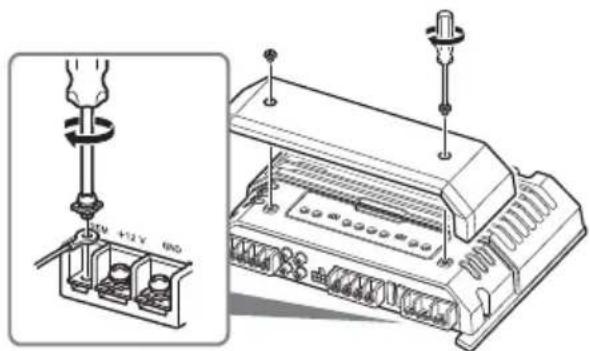
Note
When you tighten the screw, be careful not to apply too much torque as doing so may damage the screw (the torque value should be less than 1 N•m).
Power Connections
- Connect the +12 V power supply wire only after all the other wires have been connected.
- Be sure to connect the ground (earth) wire of the unit securely to a metal point of the car. A loose connection may cause a malfunction of the amplifier.
- B sure to connect the remote control wire of the car audi o unit to the remote input (REM) terminal.
-
When using a car audio unit without a remote output for the amplifier, connect the remote input (REM) terminal to the accessory power supply.
-
Use a power supply wire with a fuse (60 A) attached.
- All power wires connected to the positive battery post should be fused within 450 mm (17 ^3 /4 in) of the battery post, and before they pass through any metal.
- Make sure that the car's battery wires connected to the car (ground (earth) to chassis) are of a wire gauge at least equal to that of the main power wire connected from the battery to the amplifier.
- Dring full-power operation, a current of more than 60 A will run through the system. Therefore, make sure that the wires to be connected to the +12 V and GND terminals of this unit are at least 8-Gauge (AWG-8) or have a sectional area of more than 8 mm ^2 ( ^11/_32 in ^2 ).
Making power connections
Power connection wires (not supplied) are required.
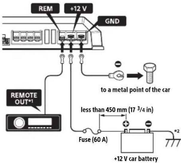
*1 If you have the factory original or some other car audio unit without a remote output for the amplifier, connect the remote input (REM) terminal to the accessory power supply. In High level input connection, the car audio unit can also be activated without need for REMOTE connection. However, this function is not guaranteed for all car audio units.
*2 Ground (earth) to chassis.
Input Connections
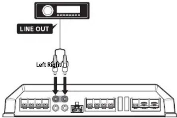
A Line input connection
With the speaker connection 1, 2, 3 or 4 (page 7, 8)
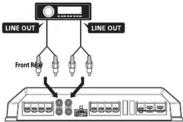
Note
You can enjoy high-resolution sound when this unit is connected to a high-resolution audio supported car audio unit (e.g. RSX-GS9).
B Line input connection
With the speaker connection 5 (page 8)
Note
You can enjoy high-resolution sound when this unit is connected to a high-resolution audio supported car audio unit (e.g. RSX-GS9).

High level input connection
With the speaker connection 1, 2, 3 or 4 (page 7, 8)
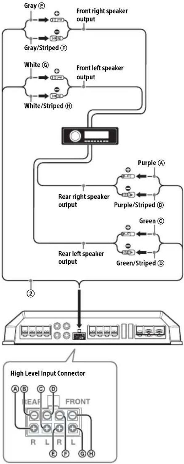
flowchart
graph TD
    A["Gray E"] --> B["Front right speaker output"]
    C["Gray/Striped F"] --> B
    D["White G"] --> E["Front left speaker output"]
    F["White/Striped H"] --> E
    G["Purple A"] --> H["Rear right speaker output"]
    I["Purple/Striped B"] --> H
    J["Green C"] --> K["Rear left speaker output"]
    L["Green/Striped D"] --> K
    M["2"] --> N["High Level Input Connector"]
    N --> O["A B C D FRONT R L R L E F G H"]
Note
Also, refer to the manual supplied with your car audio unit for further details.
Speaker Connections
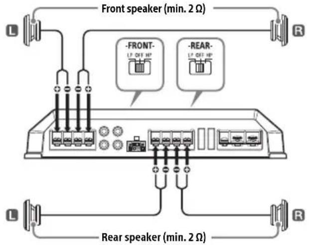
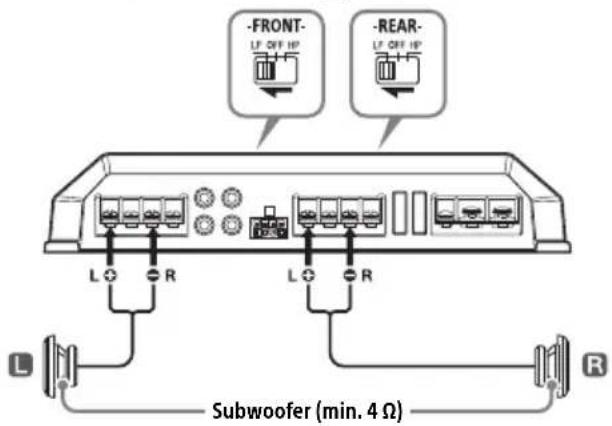
Set the FILTER selector switch on the control panel to "HP" (high-pass filter), "LP" (low-pass filter) or "OFF" according to the speaker system. Also, refer to the manual supplied with your speakers for further details.
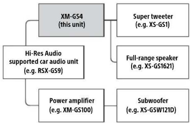
Recommended high-resolution audio system
flowchart
graph TD
    A["XM-GS4 (this unit)"] --> B["Super tweeter (e.g. XS-GS1)"]
    A --> C["Full-range speaker (e.g. XS-GS1621)"]
    A --> D["Power amplifier (e.g. XM-GS100)"]
    A --> E["Hi-Res Audio supported car audio unit (e.g. RSX-GS9)"]
    D --> F["Subwoofer (e.g. XS-GSW121D)"]
Note
Certain products shown in the diagram may not be available in your country or region.
1 6-speaker system (recommended for the high-resolution audio system)
With the input connection A or C (page 6, 7)
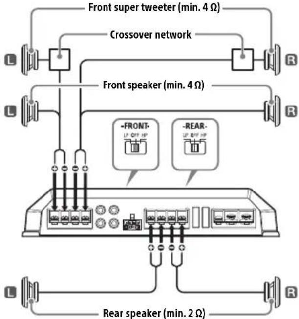
2 4-speaker system
With the input connection A or C (page 6, 7)
3 3-speaker system
With the input connection A or C (page 6, 7)
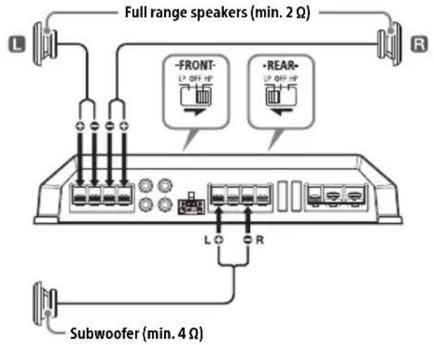
Notes
- In this system, the volume of the subwoofer will be controlled by the car audio unit fader control.
- In this system, the output signals to the subwoofer will be the combination of both the REAR L INPUT and REAR R INPUT jacks or the REAR high level input connector signals.
4 2-way system
With the input connection A or C (page 6, 7)
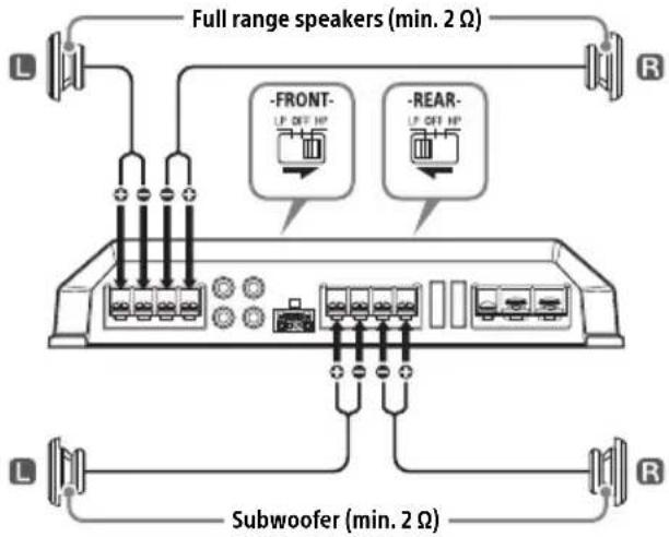
Note
In this system, the volume of the subwoofer will be controlled by the car audio unit fader control.
5 2-subwoofer system
With the input connection B (page 6)
Additional Information
Precautions
- This unit is designed for negative ground (earth) 12 V DC operation only.
- Use speakers with an impedance of 2 to 8 (4 to 8 when used as a bridging amplifier).
- Do not connect any active speakers (with built-in amplifiers) to the speaker terminals of the unit. Doing so may damage the active speakers.
- Avoid installing the unit in areas subject to:
— high temperatures such as from direct sunlight or hot air from the heater
- rain or moisture
— dust or dirt.
- If your car is parked in direct sunlight and there is a considerable rise in temperature inside the car, allow the unit to cool down before use.
- When installing the unit horizontally, be sure not to cover the fins with the floor carpet, etc.
- If this unit is placed too close to the car audio unit or antenna (aerial), interference may occur. In this case, relocate this unit away from the car audio unit or antenna (aerial).
- If no power is being supplied to the car audio unit, check the connections.
- This power amplifier employs a protection circuit* to protect the transistors and speakers if the amplifier malfunctions. Do not attempt to test the protection circuits by covering the heat sink or connecting improper loads.
- Do not use the unit on a weak battery as its optimum performance depends on a good power supply.
- For safety, keep your car audio unit volume moderate so that you can still hear other sounds.
\* Protection circuit
This amplifier is provided with a protection circuit that operates in the following cases:
— when the unit overheats
- when a DC current is generated
- when the speaker terminals are short-circuited.
The illumination indicator will change from white to red, and the unit will shut down. If this happens, take out the cassette tape or disc, turn off the connected equipment, and determine the cause of the malfunction. If the unit has overheated, wait until it cools down before use.
If you have any questions or problems concerning your unit that are not covered in this manual, please consult your nearest Sony dealer.
Maintenance
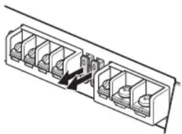
Fuse Replacement
When replacing the fuse, be sure to use one matching the amperage stated above the fuse holder. If the fuse blows, check the power connection and replace both the fuses. If the fuse blows again after replacement, there may be an internal malfunction. In such a case, consult your nearest Sony dealer.
natural_image
Technical line drawing of a multi-chamber electrical connector or socket assembly (no text or symbols)Warning
Never use a fuse with an amperage rating exceeding the one supplied with the unit as this could damage the unit.
Specifications
AUDIO POWER SPECIFICATIONS

CTA2006 Standard
Power Output: 70 Watts RMS × 4 at
4 Ohms < 1% THD+N
SN Ratio: 93 dBA
(reference: 1 Watt into 4 Ohms)
Circuit system
OTL (output transformerless) circuit,
Pulse power supply
Inputs
RCA pin jacks,
High level input connector
Input level adjustment range
0.3 - 6 V (RCA pin jacks),
3 - 12 V (High level input)
Outputs
Speaker terminals
Speaker impedance
2 - 8 Ω (stereo),
4 - 8 Ω (when used as a bridging amplifier)
Maximum output
2 Speakers: 350 W × 2 (at 4 Ω)
4 Speakers: 150 W × 4 (at 4 Ω)
Rated output
(supply voltage at 14.4 V, 20 Hz - 20 kHz, 1 %
THD)
2 Speakers: 160 W × 2 (at 4 Ω)
4 Speakers: 80 W × 4 (at 2 Ω),
70 W × 4 (at 4 Ω)
Frequency response
10 Hz - 100 kHz ( ^+ GB)
Harmonic distortion
0.05 % or less (at 1 kHz, 4 Ω)
Low-pass filter
50 - 300 Hz, 12 dB/oct
High-pass filter
50 - 300 Hz, 12 dB/oct
Subsonic filter
6 - 70 Hz, 12 dB/oct
Low boost
0 - 10 dB (40 Hz)
Power requirements
12 V DC car battery (negative ground (earth))
Power supply voltage
10.5 - 16 V
Current drain
At rated output: 33 A (4 Ω, 70 W × 4)
Remote input: 1 mA
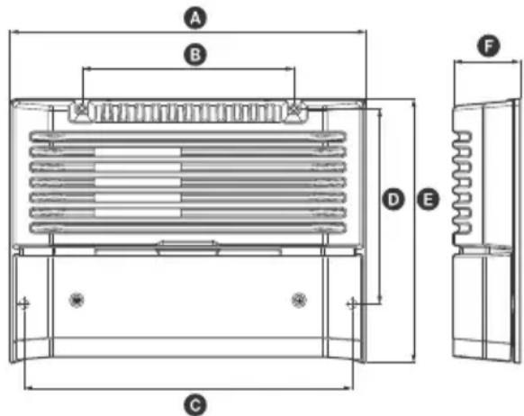
Dimensions
Approx. 272 × 51 × 202 mm (10³/4 × 2¹/8 × 8 in)
(w/h/d) not incl. projecting parts and controls

A 272 mm (10 ^3 /4 in)
B 162 mm (6 1/2 in)
© 251 mm (10 in)
D 149.5 mm (6 in)
E 202 mm (8 in)
F 51 mm (2 1/8 in)
Mass
Approx. 2.7 kg (6 lb) not incl. accessories
Package contents:
Main unit (1)
Mounting screws (4)
High level input cord (1)
Your dealer may not handle some of the above listed accessories. Please ask the dealer for detailed information.
Design and specifications are subject to change without notice.
Troubleshooting
The following checklist will assist in the correction of most problems which you may encounter with your unit. Before going through the checklist below, refer to the connection and operating procedures.
The illumination indicator does not light up.
→ The fuse is blown.
— Replace the fuse with a new one.
→ The ground (earth) wire is not securely connected.
- asten the ground (earth) wire securely to a metal point of the car.
→ The voltage going into the remote input (REM) terminal is too low.
— Turn on the car audio unit if it is not turned on.
- Use a relay if the system employs too many amplifiers.
→ Check the battery voltage (10.5 – 16 V).
The illumination indicator changes from white to red.
→ Turn off the power switch. The speaker outputs have shorted.
— Rectify the cause of the short.
→ Turn off the power switch. Make sure the speaker cord and ground (earth) wire are securely connected.
The unit becomes abnormally hot.
→ The unit heats up abnormally.
- Use speakers with suitable impedance: 2 - 8 Ω (stereo), 4 - 8 Ω (when used as a bridging amplifier).
→ Make sure to place the unit in a well ventilated location.
The sound is interrupted.
→ The thermal protector has activated.
— Reduce the volume.
Alternator noise is heard.
→ The power connecting wires are installed too close to the RCA pin cords.
— Keep the wires away from the cords.
→ The ground (earth) wire is not securely connected.
- asten the ground (earth) wire securely to a metal point of the car.
→ Negative speaker wires are touching the car chassis.
— dep the wires away from the car chassis.
The sound is muffled.
→ The filter switch is set to "HP" or "OFF".
— When connecting the subwoofer, set to "LP".
→ The filter switch is set to "LP".
— When connecting the full range speaker, set to "OFF" or "HP".
The sound is too quiet.
→ The LEVEL adjustment control is not appropriate. Turn the LEVEL adjustment control in the clockwise direction.
If these solutions do not help improve the situation, consult your nearest Sony dealer.
Installation et raccordements

Installation et raccordements
natural_image
Technical line drawing of a mechanical device with a screw and housing (no text or symbols)Raccordements
Remarque
Remarque
Remarque
natural_image
Diagram of a multi-chamber electrical connector with internal components and an arrow indicating direction (no text or symbols)Avertissement
Accentuation des graves
0 - 10 dB (40 Hz)
Alimentation requise
(l/h/p), parties saillantes et commandes non comprises
A 272 mm (10 ^3 /4 po)
B 162 mm (6 1/2 po)
© 251 mm (10 po)
D 149,5 mm (6 po)
E 202 mm (8 po)
F 51 mm (2 1/8 po)
Poids
Environ 2,7 kg (6 lb), accessoires non compris
Appareil principal (1)
Vis de montage (4)

natural_image
Technical line drawing of a multi-chamber electronic device with a screwdriver inserted (no text or symbols)Conexiones
Nota
natural_image
Diagram of a multi-chamber electrical connector with internal components and a black arrow indicating a connection (no text or symbols present)Advertencia

1 Lüftungsauslass
natural_image
Technical line drawing of a device with a screwdriver inserted, showing internal components and wiring (no text or symbols)Anschlüsse
Hinweis
natural_image
Pure technical line drawing of a mechanical or electrical component with no text, numbers, or symbolsAchtung

natural_image
Technical line drawing of a mechanical device with a screw and housing (no text or symbols)Collegamenti
Nota
natural_image
Diagram of a multi-chamber electrical connector with internal components and a directional arrow indicating flow (no text or symbols)Attenzione

1 Ventilatieopening
natural_image
Technical line drawing of a mechanical device with a screw and housing (no text or symbols)Aansluitingen
Opmerking
natural_image
Diagram of a dual-chamber electrical connector with internal components and a directional arrow indicating flow (no text or symbols)Waarschuwing
50 - 300 Hz, 12 dB/oct.
Hoogdoorlaatfilter
50 - 300 Hz, 12 dB/oct.
Subsonische filter
6 - 70 Hz, 12 dB/oct.
Lage boost
0 - 10 dB (40 Hz)
Voeding
12 V DC-autoaccu (negatieve massa)
Voedingsspanning
10,5 - 16 V
Stroomverbruik

1 Ventilationsutlopp
Släpper ut värme.
natural_image
Technical line drawing of a device with a screwdriver inserted, showing internal components and wiring (no text or symbols)Anslutningar
Obs!
natural_image
Diagram of a multi-compartment storage unit with internal compartments and a central control panel (no text or labels)Varning
OTL-krets (output transformerless),
Harmonisk distortion
0,05 % eller mindre (vid 1 kHz, 4 Ω)
Lågpassfilter
50 - 300 Hz, 12 dB/okt
Högpassfilter
50 - 300 Hz, 12 dB/okt
Subsonicfilter
6 - 70 Hz, 12 dB/okt
Låg förstärkning
0 - 10 dB (40 Hz)
Strömkrav
bilbatteri 12 V DC (negativ jordning)
natural_image
Technical line drawing of a device with a screwdriver inserted, showing internal components and wiring (no text or symbols)Conexões
Fazendo as conexões dos terminais
Observação
natural_image
Diagram of a dual-chamber electrical connector with internal components and a directional arrow indicating flow (no text or symbols)Aviso

natural_image
Technical line drawing of a device chassis with labeled components (no text or symbols present)Podłączanie
Uwaga
Uwaga
natural_image
Diagram of a multi-chamber electrical connector with internal components and a black arrow indicating direction (no text or symbols)Ostrzeżenie

natural_image
Technical line drawing of a mechanical device with a screw and base plate (no text or symbols)Подключение
Примечание
natural_image
Pure technical line drawing of a mechanical or electrical component assembly without any text, numbers, or symbolsВнимание!

natural_image
Technical line drawing of a device with a screwdriver inserted, showing internal components and wiring (no text or symbols)Підключення
Примітка
natural_image
Pure technical line drawing of a mechanical or electrical component assembly without any text, numbers, or symbolsПопередження

1 ช่องระบายความร้อน
ระบายความร้อน
natural_image
Technical line drawing of a multi-chamber electronic device with a screwdriver inserted (no text or symbols)การเชื่อมต่อ
หมายเหตุ
natural_image
Diagram of a multi-chamber electrical connector or socket assembly (no text or symbols visible)คำเตือน

1 通風口
用於散熱。
natural_image
Technical line drawing of a device with a screwdriver inserted, showing internal components and wiring (no text or symbols)連接
註
natural_image
Technical line drawing of a multi-chamber electrical connector or socket assembly (no text or symbols)警告
natural_image
Technical line drawing of a multi-chamber electrical connector or socket assembly (no text or symbols)هشدار
نکته
natural_image
Technical line drawing of a device with a handle and labeled component (no text or symbols present)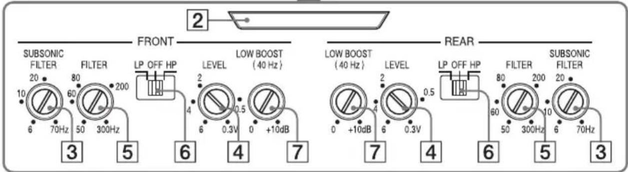
natural_image
Diagram of a multi-chamber electrical connector with internal components and a black arrow indicating direction (no text or symbols)تحذیر
flowchart
graph TD
    A[" speakers "] --> B[" router "]
    B --> C[" speakers "]
    C --> D[" router "]
    D --> E[" speakers "]
    E --> F[" router "]
    F --> G[" speakers "]
    G --> H[" router "]
    H --> I[" speakers "]
    I --> J[" router "]
    J --> K[" speakers "]
    K --> L[" router "]
    L --> M[" speakers "]
    M --> N[" router "]
    N --> O[" speakers "]
    O --> P[" router "]
    P --> Q[" speakers "]
    Q --> R[" router "]
    R --> S[" speakers "]
    S --> T[" router "]
    T --> U[" speakers "]
    U --> V[" router "]
    V --> W[" speakers "]
    W --> X[" router "]
    X --> Y[" speakers "]
    Y --> Z[" router "]
    Z --> AA[" speakers "]
    AA --> AB[" router "]
    AB --> AC[" speakers "]
    AC --> AD[" router "]
    AD --> AE[" speakers "]
    AE --> AF[" router "]
    AF --> AG[" speakers "]
    AG --> AH[" router "]
    AH --> AI[" speakers "]
    AI --> AJ[" router "]
    AJ --> AK[" speakers "]
    AK --> AL[" router "]
    AL --> AM[" speakers "]
    AM --> AN[" router "]
    AN --> AO[" speakers "]
    AO --> AP[" router "]
    AP --> AQ[" speakers "]
    AQ --> AR[" router "]
    AR --> AS[" speakers "]
    AS --> AT[" router "]
    AT --> AU[" speakers "]
    AU --> AV[" router "]
    AV --> AW[" speakers "]
    AW --> AX[" router "]
    AX --> AY[" speakers "]
    AY --> AZ[" router "]
    AZ --> BA[" speakers "]
    BA --> BB[" router "]
    BB --> BC[" speakers "]
    BC --> BD[" router "]
    BD --> BE[" speakers "]
    BE --> BF[" router "]
    BF --> BG[" speakers "]
    BG --> BH[" router "]
    BH --> BI[" speakers "]
    BI --> BJ[" router "]
    BJ --> BK[" speakers "]
    BK --> BL[" router "]
    BL --> BM[" speakers "]
    BM --> BN[" router "]
    BN --> BO[" speakers "]
    BO --> BP[" router "]
    BP --> BQ[" speakers "]
    BQ --> BR[" router "]
    BR --> BS[" speakers "]
    BS --> BT[" router "]
    BT --> BU[" speakers "]
    BU --> BV[" router "]
    BV --> BW[" speakers "]
    BW --> BX[" router "]
    BX --> BY[" speakers "]
    BY --> BZ[" router "]
    BZ --> CA[" speakers "]
    CA --> CB[" router "]
    CB --> CC[" speakers "]
    CC --> CD[" router "]
    CD --> CE[" speakers "]
    CE --> CF[" router "]
    CF --> CG[" speakers "]
    CG --> CH[" router "]
    CH --> CI[" speakers "]
    CI --> CJ[" router "]
    CJ --> CK[" speakers "]
    CK --> CL[" router "]
    CL --> CM[" speakers "]
    CM --> CN[" router "]
    CN --> CO[" speakers "]
    CO --> CP[" router "]
    CP --> CQ[" speakers "]
    CQ --> CR[" router "]
    CR --> CS[" speakers "]
    CS --> CT[" router "]
    CT --> CU[" speakers "]
    CU --> CV[" router "]
    CV --> CW[" speakers "]
    CW --> CX[" router "]
    CX --> CY[" speakers "]
    CY --> CZ[" router "]
    CZ --> DA[" speakers "]
flowchart
graph TD
    A["LINE OUT"] --> B["Line OUT"]
    C["Line OUT"] --> D["Line OUT"]
    E["Line OUT"] --> F["Line OUT"]
    G["Line OUT"] --> H["Line OUT"]
    I["Line OUT"] --> J["Line OUT"]
    K["Line OUT"] --> L["Line OUT"]
    M["Line OUT"] --> N["Line OUT"]
ملاحظة
ملاحظة
natural_image
Technical line drawing of a device with labeled component (no text or symbols present)
• presents picture picture* لتحقيق Capacity Chapter must be mentioned.
* مصر طاقة نبيضة
©2015 Sony Corporation Printed in Thailand
- Stereo Power Amplifier
- Owner's Record
- Notice for customers: the following information is only applicable to equipment sold in countries applying EU Directives
- Disposal of waste batteries and electrical and electronic equipment (applicable in the European Union and other European countries with separate collection systems)
- Features
- Table of Contents
- Operation
- Installation and Connections
- Additional Information
- Location and Function of Controls
- Ventilation outlet
- Illumination indicator
- SUBSONIC FILTER adjustment control
- LEVEL adjustment control
- Cut-off frequency adjustment control
- FILTER selector switch
- QW BOOST level control
- Parts for Installation and Connections
- Installation
- Mounting the unit
- Connections
- Note
- Power Connections
- Making power connections
- Input Connections
- A Line input connection
- B Line input connection
- High level input connection
- Speaker Connections
- Recommended high-resolution audio system
- 6-speaker system (recommended for the high-resolution audio system)
- 4-speaker system
- 3-speaker system
- Notes
- 2-way system
- 2-subwoofer system
- Precautions
- \* Protection circuit
- Maintenance
- Fuse Replacement
- Warning
- Specifications
- AUDIO POWER SPECIFICATIONS
- Troubleshooting
- The illumination indicator does not light up.
- The illumination indicator changes from white to red.
- The unit becomes abnormally hot.
- The sound is interrupted.
- Alternator noise is heard.
- The sound is muffled.
- The sound is too quiet.
- Installation et raccordements
- Raccordements
- Remarque
- Avertissement
- Conexiones
- Nota
- Advertencia
- Lüftungsauslass
- Anschlüsse
- Hinweis
- Achtung
- Collegamenti
- Attenzione
- Ventilatieopening
- Aansluitingen
- Opmerking
- Waarschuwing
- Ventilationsutlopp
- Anslutningar
- Obs!
- Varning
- Conexões
- Observação
- Aviso
- Podłączanie
- Uwaga
- Ostrzeżenie
- Подключение
- Примечание
- Внимание!
- Підключення
- Примітка
- Попередження
- การเชื่อมต่อ
- หมายเหตุ
- คำเตือน
- 通風口
- 連接
- 警告
- هشدار
Brand : SONY
Model : XMGS4
Category : Car speaker