S90 - Fitness Equipment TUNTURI - Free user manual and instructions
Find the device manual for free S90 TUNTURI in PDF.

| Product type | Stepper |
| Brand | Tunturi |
| Model | S90 |
| Dimensions (L x W x H) | 93 cm x 65 cm x 137 cm |
| Weight | 36 kg |
| Power supply | 2 x 1.5 V AA batteries |
| Maximum user weight | 110 kg |
| Functions of the meter unit | Time, Rate, Steps, Total Steps, Kcal, Pulse |
| Heart rate measurement | Wireless (integrated receiver), Polar compatible |
| Resistance | 12 positions, manual adjustment by ring |
| Usage type | Home (24 months warranty) / Commercial (12 months warranty) |
| Operating temperature | 10 °C to 35 °C |
| Storage temperature | -15 °C to 40 °C |
| Maximum humidity | 90 % |
| Maintenance | Check the tightening periodically, grease the pistons, clean with a damp cloth |
| Battery replacement | When the display becomes weak; use 2 AA batteries |
| Spare parts | Available from the dealer; provide the model and serial number |
| Standards | CE mark, EN-957 (paragraphs 1 and 8) |
| Assembly | Requires two people; tools provided |
Frequently Asked Questions - S90 TUNTURI
User questions about S90 TUNTURI
0 question about this device. Answer the ones you know or ask your own.
Ask a new question about this device
Download the instructions for your Fitness Equipment in PDF format for free! Find your manual S90 - TUNTURI and take your electronic device back in hand. On this page are published all the documents necessary for the use of your device. S90 by TUNTURI.
USER MANUAL S90 TUNTURI
INFORMATION AND WARNINGS
Read this guide through carefully before assembling, using or servicing your fitness equipment. Please keep the guide somewhere safe; it will provide you now and in the future with the information you need to use and maintain your equipment. Always follow these instructions with care.
The equipment is covered by the Tunturi warranty. In home use, the warranty period is 24 months, in commercial use 12 months. The warranty does not cover damage due to shipping or negligence of assembly, use, adjustment or maintenance instructions described in this manual. Changes or modifications not expressly approved by Tunturi Oy Ltd will void the user's authority to operate the equipment.
NOTE ABOUT YOUR HEALTH
- Before you start any training, consult a physician to check your state of health.
- If you experience nausea, dizziness or other abnormal symptoms while exercising, stop your workout at once and consult a physician.
- To avoid muscular pain and strain, begin each workout by warming up and end it by cooling down. Don't forget to stretch at the end of the workout.
NOTE ABOUT THE EXERCISING ENVIRONMENT
- The equipment is not to be used outdoors.
- Place the equipment on a firm, level surface. Place the equipment on a protective base to avoid any damages to the floor beneath the equipment.
- Make sure that the exercising environment has adequate ventilation. To avoid catching cold, do not exercise in a draughty place.
- In training, the equipment tolerates an environment measuring +10°C to +35°C. The equipment can be stored in temperatures ranging between -15°C and +40°C. Air humidity in the training or storage environment must never exceed 90%.
NOTE ABOUT USING THE EQUIPMENT
- If children are allowed to use the equipment, they should be supervised and taught to use the equipment properly, keeping in mind the child's physical and mental development and their personality.
- Before you start using the equipment, make sure that it functions correctly in every way. Do not use a faulty equipment.
- Press the keys with the tip of the finger; your nails may damage the key membrane.
- Never lean on the interface.
- Only one person may use the equipment at a time.
- Hold the handlebar for support when getting on or off the equipment. Keep at least one hand on the handlebar when exercising.
- Wear appropriate clothing and shoes when exercising.
- Protect the meter from sunlight and always dry the surface of the meter if there are any drops of sweat on it.
- The equipment must not be used by persons weighing over 110 kg.
- Do not attempt any servicing or adjustments other than those described in this guide. The given service instructions must be followed carefully.
SAVE THIS INSTRUCTION MANUAL
WELCOME TO THE WORLD OF
TUNTURI EXERCISING!
Your choice shows that you really want to invest in your well being and condition; it also shows you really value high quality and style. With Tunturi Fitness Equipment, you've chosen a high quality, safe and motivating product as your training partner. Whatever your goal in training, we are certain this is the training equipment to get you there. You'll find information about using your exercise equipment and what makes for efficient training at Tunturi's website at WWW.TUNTURI.COM.
ASSEMBLY
The parts are packed in two separate packages. Check that all the following parts are in the packages:
- H-frame
- Vertical frame
- Shocks (2)
-
Handlebars (3)
-
Meter
-
Assembly kit (contents marked with in the spare part list): keep the assembly tools, as you may need them e.g. for adjusting the equipment.
If you notice that a part is missing, contact the dealer and give the model (S90), serial number and spare part number from the list at the back of the manual. The package includes a silicate bag for absorbing moisture during storage and transportation. We recommend two persons for the assembly. Assemble the device as follows (left, right, front and back are as seen from the exercising position):
H-FRAME AND VERTICAL FRAME
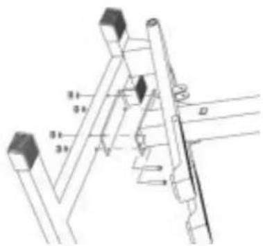
Place the plastic insulation plate between the vertical and the H-frame. Insert 4 M8x55 mm button head bolts up through the bottom of the H-frame. Place the vertical frame over the bolts. Add a washer to each bolt and secure each using the 5 mm hexagon key and the 13 mm open-end wrench and the M8 lock nut provided. Lift the climber back into the upright position.
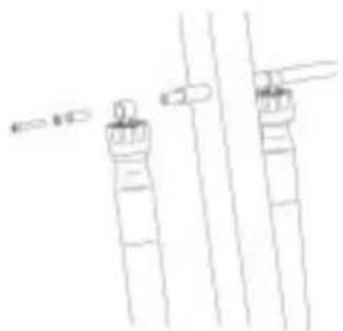
SHOCK ABSORBERS
natural_image
Simple line drawing of two vertical cylindrical objects with protruding wires (no text or symbols)Attach the end of the shock absorber that contains the resistance adjustment mechanism to the left side of the vertical frame. Slide the end of the shock absorber and a suitable spacer over the shock mount shaft on the left side of the vertical frame. Secure with the M8x40 mm button head bolt and lock washer using the 5 mm hexagon key provided. Attach the right shock absorber in the same manner.
natural_image
Pure technical line drawing of mechanical components without any text, numbers, or symbolsSlide a metal spacer inside the ring on the bottom of the shock absorber. Fasten the ring to the bracket on the left foot pedal with the M8x40 mm button head bolt and with the M8 lock nut. Use the 13 mm open-end wrench to hold the nut while you tighten the bolt with the 5 mm hexagon key provided. NOTE! Be careful not to overtighten the bolt as this may crack the plastic bushing. Attach the right shock absorber to the right foot pedal in the same manner.
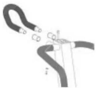
HANDLEBARS
natural_image
Pure mechanical diagram showing a pipe connection with no text, numbers, or symbolsSlide bushing and the upper end of the left handlebar into the mount on the upper end of the vertical frame. Slide the lower end over the spacer. Secure the top of the handlebar with one M8x20 button head bolt and lock washer using the 5 mm hexagon key provided. Attach the right handlebar in the same manner.
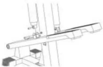
TRIBAR
natural_image
Diagram of a cable or wire being inserted into a pipe, showing no text or symbolsSlide the remaining mount bushings into the front mounts on the vertical frame. Insert the ends of the Tribar into the mount. Secure the Tribar with two M8x20 button head bolts and lock washers using the 5 mm hexagon key provided.
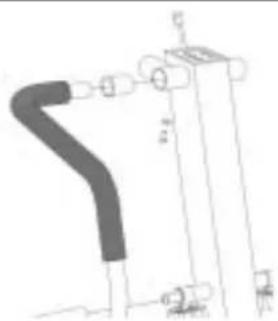
METER
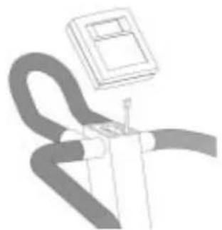
natural_image
Illustration of a curved mechanical component with a rectangular housing above it (no text or symbols)Open the battery case cover on the back of the meter case and insert two 1.5 V AA-batteries to the battery case following the + and - markings. Plug the meter cable into the socket on the rear of the meter. Secure the meter into place by setting it on the meter mount and sliding it down until firmly in place. NOTE! Make sure the meter cable is not pinched during the assembly as this can cause the meter to not function correctly.
USE
Resistance is adjusted by turning the adjustment ring located on the hydraulic cylinders (12 different resistance levels). The arrow on the shock indicates the chosen resistance level.
Start with slow tempo, long step height and low resistance. Gradually increase tempo and resistance and shorten step height according to your own condition. Keep your head up and neck long in order to avoid stress on your neck, shoulders and back. Keep also your back straight. Make sure, that your feet are centered on the foot pedals and that your hips, knees, ankles and toes are facing forward. Keep your body weight centered over your lower body regardless of whether you lean forward or stand upright. By shifting your weight forward or back you can concentrate the workout toward different lower body muscles. Stop your workout by gradually decreasing tempo and resistance. Lengthen your step height until your heart rate has returned to normal. Don't forget to stretch afterwards.
To strengthen cardiovascular system, maintain low resistance, but high tempo. Exercising with higher resistance and slow tempo strengthens correspondingly your back and hips.
METER
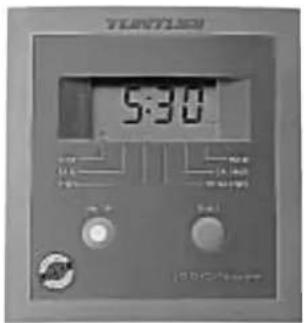
KEYS
ON/OFF
Switches power on and off.
When you switch on the meter, it displays the time and begins count-up automatically.
SELECT
Alternates modes and displays.
FUNCTIONS
TIME
(Clock symbol) Time count-up (00:00-).
RATE
(Rabbit symbol) Steps/min.
STEPS (
Stairway symbol) Step count-up (000.0-).
TOTAL STEPS
(Mountain symbol) Shows the total steps on the climber in thousands (1000 = 1). Total steps can be reset to zero by pressing the small reset key in the bottom of the meter.
KCAL
(Hamburger symbol) Estimated energy consumption at 7/16 kcal per step.
PULSE
(Heart symbol) Heart rate measurement (40 - 240).
HEART RATE MEASUREMENT
The S90 is fitted with an internal heart rate receiver to make them compatible with Polar telemetric heart rate transmitters. The transmitter may be purchased as an accessory. Exercise within different heart rate ranges affects the body in different ways. For example, exercise of long duration within a heart rate range that is about 50-60 % of the maximum heart rate burns fat, or helps you lose weight, whereas exercise in a range that is about 70-80 % of the maximum develops the heart and respiratory system, and overall endurance, i.e. it improves your condition.
If you don't know your own maximum heart rate you can use the following formula as a guide:
208-0,7 X AGE
However, it is advisable to make sure by consulting your doctor.
The most reliable heart rate measurement is achieved with a telemetric device, in which the electrodes of the transmitter fastened to the chest transmit the pulses from the heart to the meter by means of an electromagnetic field.
NOTE! If you have a heart pacemaker, you may use the heart rate measurement transmitter only on a physician's approval!
If you want to measure your heart rate this way during your workout, moisten the grooved electrodes on the transmitter belt with saliva or water. Fasten the transmitter just below the chest with the elastic belt, firmly enough so that the electrodes remain in contact with the skin, but not so tight that normal breathing is prevented. The transmitter automatically transmits the heart rate reading to the meter up to a distance of about 1 m. If you wear the transmitter and belt over a light shirt, moisten the shirt slightly at the points where the electrodes touch the shirt.
MAINTENANCE
The S90 requires very little maintenance. Check, however, from time to time that all screws and nuts are tight, and apply light grease or vaseline to the pivot points of the shocks if necessary. Clean the climber from dirt and dust with a damp cloth or towel. Do not use solvents.
If the device is not functioning properly during use, contact your Tunturi dealer immediately. Always give the model (S90) and the serial number of your device.
Despite continuous quality control, faults or malfunctions due to individual components may arise. It is, however, unnecessary to send the whole device to be repaired as the fault can in most cases be repaired by replacing the component in question.
CHANGING THE BATTERIES
If the meter display becomes very weak or there is no display at all, change the batteries. Remove the meter from its mount on top of the main mast. Open the battery cover on the back of the meter case and remove the old batteries. Insert new batteries (two 1.5 V AA-batteries) to the battery case following the + and - markings. Push the battery case cover back into place. Slide the meter onto its mounting on top of the vertical frame.
STORAGE
To prevent malfunctioning, store the stepper in a dry space with as little temperature variation as possible, protected from dust.
DIMENSIONS
| Length | 93 | cm |
| Width | 65 | cm |
| Height | 137 | cm |
| Weight | 36 | kg |
This product carries the CE label.
All Tunturi steppers meet EN precision and safety standards (EN-957, parts 1 and 8).
Due to our continuous policy of product development, Tunturi reserves the right to change specifications without notice.
natural_image
Simple line drawing of two vertical cylindrical objects with a small object on top, connected by lines (no text or symbols)natural_image
Pure mechanical assembly diagram without any text, numbers, or symbolsnatural_image
Pure technical line drawing of a mechanical component without any text, numbers, or symbolsnatural_image
Diagram of a hand holding a curved pipe with two connectors (no text or symbols)natural_image
Illustration of a person using a handheld device with a small screen above (no text or symbols visible)natural_image
Pure line drawing of two vertical cylindrical objects with horizontal lines and arrows, no text or symbols presentnatural_image
Technical line drawing of a mechanical assembly with no visible text or symbolsnatural_image
Pure mechanical diagram showing a curved pipe or duct connected to a rectangular block with mounting holes (no text or symbols)natural_image
Diagram of a mechanical or electrical component with curved and straight lines, no visible text or symbolsnatural_image
Pure electrical circuit lines without any symbolsnatural_image
Simple line drawing of two vertical cylindrical objects with a small object on top, connected by lines (no text or symbols)natural_image
Technical line drawing of a mechanical assembly with pipes and supports (no text or symbols)natural_image
Pure mechanical diagram showing a curved pipe or duct connected to a vertical cylindrical component (no text or symbols)natural_image
Diagram of a cable or wire being inserted into a pipe (no text or labels)natural_image
Illustration of a person holding a device with a mounted box (no text or symbols visible)natural_image
Pure technical line drawing of two vertical cylindrical components with no text or symbolsnatural_image
Technical line drawing of a mechanical assembly with no visible text or symbolsnatural_image
Pure mechanical diagram showing a curved pipe or duct connected to a vertical component with no text, numbers, or symbols.natural_image
Diagram of a medical procedure showing a curved tube inserted into a device (no text or labels)natural_image
Illustration of a person holding a pen, with a small box above (no text or symbols)natural_image
Pure technical line drawing of two mechanical components with no text or symbolsnatural_image
Technical line drawing of a mechanical assembly with no visible text or symbolsnatural_image
Pure mechanical component diagram without any text, numbers, or symbolsnatural_image
Diagram of a hand holding a curved pipe with a small object nearby (no text or symbols)natural_image
Illustration of a person using a tool on a curved line, with a small inset showing a device (no text or symbols)natural_image
Simple line drawing of two vertical cylindrical objects with arrows pointing to them, no text or symbols present.natural_image
Technical line drawing of a mechanical assembly with pipes and supports (no text or symbols)natural_image
Pure technical line drawing of a mechanical component without any text, numbers, or symbolsnatural_image
Diagram of a cable or wire being inserted into a plug (no text or symbols present)natural_image
Illustration of a person using a handheld device with a small box above (no text or symbols visible)natural_image
Simple line drawing of two vertical cylindrical objects with arrows pointing to them, no text or symbols present.natural_image
Technical line drawing of a mechanical assembly with no visible text or symbolsnatural_image
Pure mechanical diagram showing a curved pipe or duct connected to a vertical component with multiple cylindrical ends (no text or symbols)natural_image
Diagram of a curved pipe with attached clamps, no text or symbols presentnatural_image
Abstract line drawing of a curved pipe with a small inset box (no text or symbols)NÄPPÄIMET
ON/OFF

natural_image
Black metal exercise stand with adjustable arms and legs (no text or symbols visible)TUNTURI®
THE MOTOR - it's you.
TUNTURI OY LTD
P.O.BOX 750, FIN-20361
Turku, Finland
Tel. +358 (0)2 513 31
Fax +358 (0)2 513 3323
www.tunturi.com
©Tunturi Oy Ltd