
SL1000R - Turntable TECHNICS - Free user manual and instructions
Find the device manual for free SL1000R TECHNICS in PDF.
| Product type | Direct drive turntable |
| Brand | Technics |
| Model | SL1000R |
| Motor | Brushless DC motor, coreless direct drive |
| Platter | Three-layer construction: brass, die-cast aluminum, damping rubber; diameter 323 mm; weight 7.9 kg (rubber sheet included) |
| Rotation speeds | 33 1/3, 45, 78.26 rpm |
| Wow and flutter | 0.015% WRMS (JIS C5521) |
| Pitch control range | ±16% |
| Starting torque | 0.39 N·m (4.0 kg·cm) |
| Tone arm | Static balanced magnesium type; effective length 254 mm; overhang 15 mm; error angle <1°48' (outer), <0°30' (inner); offset angle 21° |
| Arm height adjustment | 0 to 15 mm |
| Stylus force | 0 to 4 g (direct reading) |
| Applicable cartridge weight (including headshell) | 15.9 to 31.0 g (with auxiliary weights) |
| Output terminal | PHONO (DIN connector) |
| Power supply | 110-240 V AC, 50/60 Hz |
| Power consumption | 10 W (on), 0.05 W (off) |
| Dimensions (W × H × D) | Main unit without cover: 524 × 168 × 392 mm; with cover: 531 × 188 × 399 mm; control unit: 110 × 84 × 350 mm |
| Weight | Main unit without cover: 38.0 kg; with cover: 40.2 kg; control unit: 2.1 kg |
| Operating temperature | 0 °C to +40 °C |
| Operating humidity | 35% to 80% RH (no condensation) |
| Included accessories | Platter, slip mat, dust cover, counterweight, auxiliary weights (small, medium, large), 45 rpm adapter, overhang gauge, set of screws, hex wrench, detachable handles, isolator attachments, power cords (4 types), control unit |
| Main features | Coreless motor for smooth rotation; three-layer platter; high-sensitivity magnesium tonearm; anti-vibration design with five-layer plinth and isolators; separate control unit; support for up to three tonearms; adjustable torque control (5 levels) |
| Maintenance and cleaning | Clean the stylus with a soft brush from base to tip; use a record cleaning solution; wipe the cover and housing with a soft cloth; do not use solvents |
| Safety | Disconnect before any connection; use two people for transport; do not expose to moisture; do not place heavy objects on the unit; follow grounding instructions |
Frequently Asked Questions - SL1000R TECHNICS
User questions about SL1000R TECHNICS
0 question about this device. Answer the ones you know or ask your own.
Ask a new question about this device
Download the instructions for your Turntable in PDF format for free! Find your manual SL1000R - TECHNICS and take your electronic device back in hand. On this page are published all the documents necessary for the use of your device. SL1000R by TECHNICS.
USER MANUAL SL1000R TECHNICS
Winsberging 15, 22525 Hamburg, Germany

For the U.S.A.
Panasonic Corporation of North America
Two Riverfront Plaza,Newark,NJ 07102-5490
www.shop.panasonic.com
For Canada / Pour le Canada
Panasonic Canada Inc.
5770 Amtioer Drive,
Mississauga, Ontario.
LW213
www.panasonic.com
© Panasonic Corporation 2018
For the United Kingdom and Ireland
For Continental Europe
Panasonic Corporation
Web Site: http://www.panasonic.com
EnCfGeFfiSpDuSwDaFiPo
TOBMO217
S02106AK1
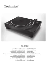
SL-1000R
Direct Drive Turntable System
Operating Instructions
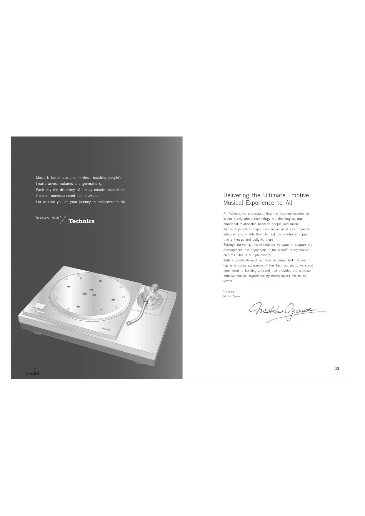
Delivering the Ultimate Emotive Musical Experience to All
At Technics we understand that the listening experience is not purely about technology but the magical and emotional relationship between people and music.
We want people to experience music as it was originally intended and enable them to feel the emotional impact that enthuses and delights them.
Through delivering this experience we want to support the development and enjoyment of the world's many musical cultures. This is our philosophy:
With a combination of our love of music and the vast high-end audio experience of the Technics team, we stand committed to building a brand that provides the ultimate emotive musical experience by music lovers, for music lowers.
Director
Michiko Ogezaki
nolokogaw
Thank you for purchasing this product.
Please read these instructions carefully before using this product, and save this manual for future use.
- About descriptions in these operating instructions
- Paper to be referred to are indicated as "in 90".
Pages to be referred to are indicated as " 100" - The illustrations shown may differ from your unit.
For the U.S.A. and Canada
If you have any questions, visit
U.S.A.: http://shop.panasonic.com/support
Canada: www.panasonic.ca/english/support
Register online at http://shop.panasonic.com/support (U.S. customers only)
For the United Kingdom and Ireland customers
Sales and Support Information
Customer Communications Centre
For customers within the UK: 0333 222
For customers within Ireland: 01 447 526-389-516-516-526-526-526-526-526-526-526-526-526-526-526-526-526-526-526-526-526-526-526-526-526-526-526-526-526-5
Monday-Friday 9.00 am-5.00 pm, (Excluding public holidays).
For further support on your product, please visit our website: www.technics.com/uk/
Features
Coreless direct drive motor for smooth and accurate rotation
- The new coreless direct drive motor can reduce minute vibration during rotation by ensuring strong torque to drive the grand class turntable.
- The high-precision motor control technology changes the drive mode according to the motor operation status to achieve high rotation accuracy.
Three-layer turntable for stable rotation
The three-layer turntable structure is consisting of brass, aluminum die cast and deadening rubber that is against unwanted resonance and attached to the bottom surface.
- Dense tungsten weights are located on the outer periphery of the brass part to deliver large inertial mass.
High-sensitivity tone arm for accurate reading of record grooves
A lightweight, high damping magnesium tone arm pipe has been adopted.
The tone arm base is tightly integrated with the turntable to minimize vibration of the turntable base.
04 05:
English
Thorough anti-vibration design with the five-layer cabinet and insulator
The high-rigidity five-layer cabinet is composed of different types materials such as aluminum, aluminum cie-cast and BMC.
- Silicon rubber with high damping characteristics and excellent long-term reliability is used in the insulator to shut out external vibration.
Seeking for ideal sound with excellent system scalability
- When combined with a separately sold tone arm base ( 32) , in addition to the standard tone arm, maximum three short or long tone arms in total (regardless of the manufacturer), including the standard tone arm.
Special control unit that can eliminate unwanted noise interference with the main unit
- The power circuit and control circuit are separated to minimize unwanted external noise interference with the main unit and stored in a single control unit.
- The new switching power supply with a noise reduction circuit has been developed to reduce noise in voltage supply.
Table of contentsIntroduction
Before use
| Safety precautions | 06 |
| IMPORTANT SAFETY INSTRUCTIONS | 07 |
| Accessories | 09 |
| Parts Name | 10 |
Getting started
| Unpacking and preparation | 12 |
| · Notes for taking out the goods from the package box and transporting | 12 |
| Putting the player together | 14 |
| Fitting the turntable | 15 |
| Fitting the turntable mat | 15 |
| Attaching the head shell | 15 |
| Attaching the balance weight | 15 |
| Connections and installation | 16 |
| • Connecting the output terminal and AC IN terminal / Connecting the control unit | 16 |
| • Connecting the pre-main amplifier and component / Connecting the power plug and earth ground | 16 |
| • Installation | 18 |
| • Insulator attachment | 19 |
| • Fit the dust cover | 19 |
| Adjustment | 20 |
| Horizontal balance | 20 |
| Stylus pressure | 20 |
| Anti-skating | 21 |
| Tone arm height | 22 |
| Armlift height | 23 |
Blaying back
| Playing records | 24 |
| Pitch control (fine adjustment to pitch) | 26 |
| Operation and display of the control unit | 27 |
| - Turntable speed setting | 27 |
| - Switching the display mode | 27 |
| - Turntable speed measurement | 27 |
| - Display dlimmer setting | 28 |
| - Adjusting the torque to rotate the turntable at a constant speed | 28 |
Maintenance
| Maintenance | 29 |
| Troubleshooting guide | 30 |
| Specifications | 31 |
| Optional Products | 32 |
| Preparing the head shell / cartridge (not included) | 33 |
| Limited Warranty (ONLY FOR U.S.A.) | 336 |
| Limited Warranty (ONLY FOR CANADA) | 337 |
English
Safety precautions
Warning
Unit
To reduce the risk of fire, electric shock or product damage
Do not expose this unit to rain, moisture, dripping or splashing.
Do not place objects filled with liquids, such as vases, on this unit.
- Use only the recommended accessories.
Do not remove chovers. Do not remove this unit.
Refer servicing to qualifico service personnel
- Do not let metal objects fall inside this unit.
- Do not place heavy items on this unit.
AC mains lead
To reduce the risk of fire, electric shock or product damage
Ensure that the power supply voltage corresponds to
- Insert the mains plug fully into the socket outlet.
Do not pull, bend, or place heavy items on the lid. Do not be held the time with your hands.
- Hold onto the mains plug body when disconnecting the
pug.
The minors plug is the disconnecting device.
Install this unit so that the mains plug can be unplugged from the socket outlet immediately.
Ensure the earth pin on the mains plug is securely connected to prevent electrical shock.
- An apparatus with CLASS I construction shall be
connected to a mainssocket outlet with a protective path connection.
Caution
Unit
Do not place sources of naked flames, such as lighted candles on this unit.
This unit may receive radio interference caused by mobile telephones during use.
If such interference occurs, please increase separation between this unit and the mobile telephone.
This unit is intended for use in moderate and tropical conditions.
Do not put any objects on this unit.
This unit becomes not while it is on. Always use two people or more to install or move the
unit
Placement
Place this unit on an even surface.
To reduce the risk of fire, electric shock or product damage.
Do not install or place this unit in a blockcase, built in cabinet or in another confined space.
Ensure this unit is well ventilated.
- Do not obstruct this unit's ventilation openings with
Newspapers, tablocks, curtains, and simila Do not expose this unit to direct sunlight, but
temperatures, high humidity, and excessive vibration. -Explain that the placement location is sturdy enough
- Ensure that the placement location is clearly chongg in accomodate the weight of this unit (>31)
Do not lift or carry this unit by holding the knots. Doing so may cause this unit to fall, resulting in numerical injury.
or ma fction of this unit.
06 07:
English
Caution for AC Mains Lead
(Tor the AC mains plug of three pins)
For your safety, please read the following text carefully. This assurance is supplied with a modified three pin pins
plug for your safety and convenience. A 10 cm diameter, 3 inch wide, in the size
Should the fuse need to be replaced please ensure that the
replacement fuse has a rating of 10-impere and that it is approved by ASIA or BSI to BS 1362.
Check for the ASTA mark or the BSI mark in the bodyof the June 19th the two colour a remarkable blue cover map
must ensure that it is refitted when the fuse is replaced.
If you lose the Tux Cover the program must not be used until a replacement cover is obtained.
A replacement fuse cover can be purchased from your local dealer.
Before use
Remove the connector cover
How to replace the fuse
The location of the fuse differ according to the type of AC mains mix (flowers A and B).
Confirm the AC mains plug fitted and follow the
Instructions below. Illustrations may differ from actual AC mains plug.
1. Open the fuse cover with a screwdriver.


- Replace the fuse and close or attach the fuse cover.


Disposal of Old Equipment
Only for European Union and
countries with recycling systems
These symbols on the products, packaging, and/or accompanying documents mean that used electrical and electronic products must not be mixed with general household waste.
For proper treatment, recovery and recycling of old products, please take them to applicable collection points in accordance with your national legislation.
By disposing of them correctly, you will help to save valuable resources and prevent any potential negative effects on human health and the environment. For more information about collection and seduction
For more information about collection and recycling, please contact your local municipality.
Penalties may be applicable for incorrect disposal of this waste, in accordance with national legislation.
IMPORTANT SAFETY INSTRUCTIONS
For the U.S.A. and Canada
Read these operating instructions carefully before using the program. Follow the above instructions as described in
the applicable safety instructions listed below.
Keep these operating instructions handy for future
reference.
- Read these instructions.
3 feed all wrappings
4 Follow all instructions.
5 Do not use this apparatus near water.
B. clean my with dry cloth. 7. Do not lock any equipment
-
Be not block any verbal/operating operations instead in accordance with the manufacturer's instructions.
-
Do not install near any heat sources such as
radiators, heat registers, slowes, or other apparatus (including the light source and lamp).
- Do not defeat the safety purpose of the
or grounding-type plug. A polarized plug has two
blades with one wider than the other. A grounding type
plug has two blades and a third grounding plug. The wide blade or the thin prep are provided for your
safety . If the provided plug does not fit into your outlet
consult an electrician (
- Protect the power card from being walked on or
pinched particularly at plugs,convenience receptacles
and the point where they exit from the apparatus.
11 Only use attachment/accessors specified by the manufacturer.
12 Use only with the cart, stand.
tripod, bracket, or table specified by the sequence of letters on each side.
the amount. When a card is used
use caution when moving t
apparatus combination to afrom this over.
13 Unplug this apparatus during lightning storms or when you want for large amounts of rain.
- Refer all servicing to qualified service personnel.
Servicing is required when the apparatus has been
damaged in any way, such as power supply cord or
plog's damaged, liquid has been spilled or objects have fallen into the容器, the容器 has
been exposed to rain or moisture, does not operate.
nurnally, or has been
Warning
Unit
To reduce the risk of fire, electric shock or product
damage,
- Do not expose this unit to rain, moisture, dipping or splashing.
Do not place objects filled with liquids, such as vases.
on the unit.
- Use only the recommended accessories.
-Do not repair this unit by yourself.
Refer servicing to qualified service personnel.
IMPORTANT SAFETY INSTRUCTIONS (continued)
For the U.S.A. and Canada
The following mark and symbols are located on the bottom of the unit.

CAUTION
CAUTION
RISK OF ELECTRIC SHOCK
DO NOT OPEN

TO REDUCE THE RISK OF ELECTRIC
SHCK,58NOTRE0E
NOUSER SERVICEABLE PARTS INNDELLI BLUINFIEE RENTOIOOHN
SLVWICL PERSONNEL

The lightning flash with arrowhead symbol within an arrow from the body, is represented to denote the lightning
e
the products and/or that may be classified
magnitude to constitute a risk of electric shock to persons.
The exdation point with an equalateral triangle is
reduces to such that the pressure of impelleroperates and compliance (involves) is no
The literature on computing the application
Conforms to UL STD 62368-1
Certified 1CAN/CSA STD C22.2 No.62368-1
THE FOLLOWING APPLIES ONLY IN THE U.S.A. FCC Note:
This equipment has been tested and found to comply with the limits for a Class B digital device, pursuant to Part 15 of the FCC Rules.
These limits are designed to provide reasonable protection against harmful interference in a residential installation. This equipment generates, uses and can radiate radio frequency energy and, if not installed and used in accordance with the instructions, may cause harmful interference to radio communications.
However, there is no guarantee that interference will not occur in a particular installation. If this equipment does cause harmful interference to radio or television reception, which can be determined by turning the
equipment off and on, the user is encouraged to try to correct the interference by one or more of the following measures:
-
Recipient or relocate the receiving antenna.
-
Increase the separation between the equipment and
1.
- Convert the equipment into a single on a clean
Consult the dealer or an experienced radio
technician for help.
FCCCA
To assure continued compliance, follow the attached installation instructions and use only shielded interface cables when connecting to periformal devices.
Any changes or modifications not expressly sponsored by the party responsible for compliance could void the user's authority to operate this equipment.
This device complies with Part 15 of the FCC Rules.
Operation is subject in the following two conditions:
(1) This device may not cause harmful interference, and
(2) this device must accept any interference rec
including interference that may cause undesired
- INTRODUCTION
Responsible Party:
Panasonic Corporation of North America
Two Riverfront Plaza, Newark, NJ 07102-5490
Support Contact: http://shop.panasonic.com/support
THE FOLLOWING APPLIES ONLY IN CANADA. CAN ICES-3(B)/NMB-3(B)

Information on Disposal in other Countries outside the European Union
This symbol is only valid in the European
Union
If you wish to discard this product, please
contact your local authorities or dealer and
ask for the correct method of disposal.
Accessories
In order to prevent damage during shipping some of the equipment has been disassembled. Please check and identify the supplied accessories.
| AC mains lead (1 pc.) (K2CG3YY00191) | AC mains lead (1 pc.) (K2CM3YY00041) | AC mains lead (1 pc.) (K2CS3YY00033) |
| AC mains lead (1 pc.) (K2CT3YY00081) | Turntable mat (1 pc.) (RGS0008) | Auxiliary weight (1 set) small (TPAKK61) mid (TPAKK62) big (TKKH51561) |
| Overhang gauge (1 pc.) (RMR2210-W) | EP record adaptor (1 pc.) (TEKX077) | Screw set for turntable (1 set) (TYL0194) • Screws long (3 pc) • Washers (3 pc) • Belleville springs (3 pc) |
| Balance weight (1 pc.) (TYL0189) | Dust cover (1 pc.) (TXP0046) | Turntable (1 pc.) (TYL0195) |
| Hex wrench (1 pc.) (TTK0004) | Delachable handle (2 pc.) (TXQ0020) | Insulator attachment (4 pc.) (TEKLO21) |
The model numbers of the accessories are as of February 2018. They are subject to change without notice.
- Keep the packaging materials after taking out the goods
You will need them when carrying the product for a long distance.
- Follow the local regulations when disposing of the product
Do not use any other AC mains lead except the supplied one.
- Keep the auxiliary weight, screws and washers out of reach of children to prevent swallowing.
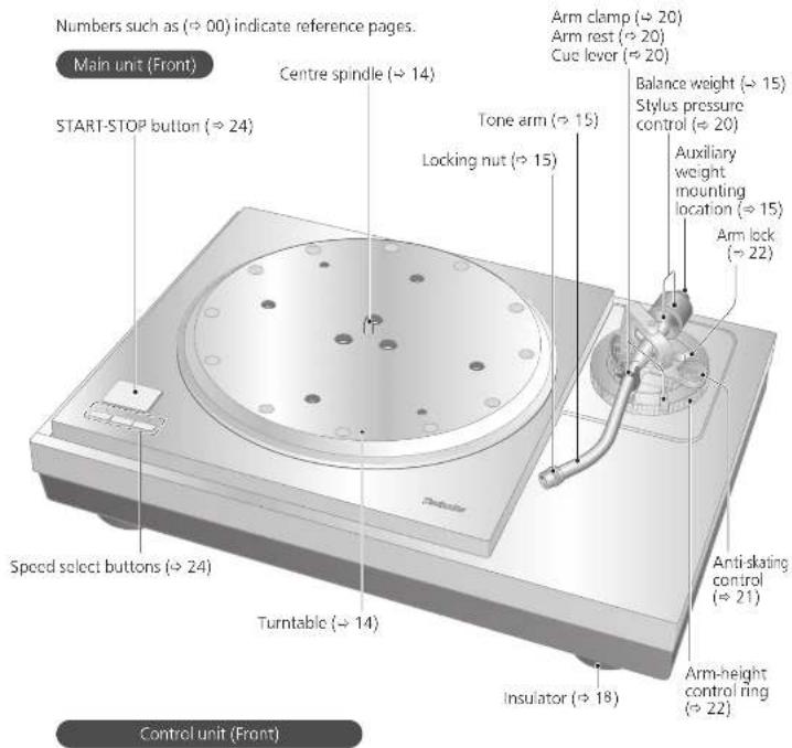
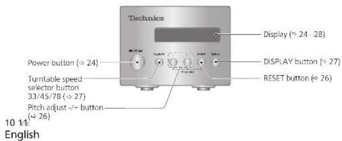
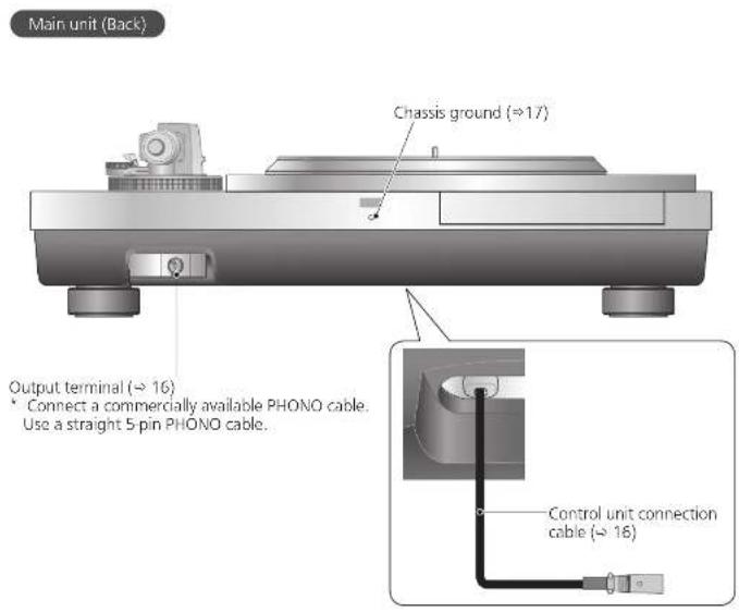
Parts Name
Unpacking and preparation
Notes for taking out the goods from the package box and transporting
Attention
Always use two or more people to take out and transport the main unit.
- Be careful not to lose balance if lifting the unit with your hands at non-optimal position.
- You may damage your back.
You may lose balance on the stairs and the like, which may lead to injury.
- Be careful not to catch your fingers when taking out the main unit.
- Be careful not to catch your fingers in the gap between the bottom of the main unit and floor.
- Keep the packaging materials after taking out the goods.
Take out the goods after deciding the installation location.
For notes regarding installation, see "Installation" (→18).
12
English
Take out the accessory box, dust cover, packing cushion, and turntable sheet.
- Keep accessories out children's reach.
- The main unit, dust cover, and control are wrapped in protective sheets.
2Put your hands between the packing cushions (Dotted line area of the package box top view) and slowly lift the main unit to take it out. Always perform this task using two or more people.
- Be very careful when lifting the main unit.
Hold the main unit from the bottom to
prevent it from slipping from your hands.
Perform the task using both hands to not lose balance.
Lifting task image
Take out the control unit, turntable, and operating instructions
13
English
Putting the player together
In order to prevent damage during shipping, some of the equipment has been disassembled. Put the player together in the following order.
Attention
Do not connect the AC mains lead until set up is complete.
- When fitting the turntable, prevent foreign material from getting in between the main unit and turntable.
14 15
English
Fitting the turntable
1
Tighten the detachable handle screws into the detachable handle mounting holes (two locations) on the
turntable. Slowly lift the turntable and then lower it in such a way as to insert the center spindle into the hole in the center of the turntable.
Attention
- Tighten the detachable handle by turning it 5 or more times. If you have tightened it until the end, loose a little bit. Do not tighten it firmly.
- Be careful when handling the turntable, as it might
Wipe off fingerprints or dirt with a soft cloth.
2 Slowly lower the turntable while aligning the rotor shaft fix holes (three locations) with the rotor shaft.
- Mount by using the rotor shaft with the arrow mark as a guide. (+14)
Attention
- If the rotor shafts are misaligned, a gap remains between the turntable and main unit and you cannot mount the turntable correctly. Do not force the turntable downward.

3 Attach the washers, belleville springs, and screws for turntable to the rotor shaft fix holes, and tighten the mounting screws securely.
Attention
- When tightening screws, do not allow screw heads to protrude from the top surface of the turntable.
- Tighten the three screws uniformly. Failing to do so may make the turntable rattle or rotate unstably. Make sure none of the screws are loose.
To remove the turntable
Looscn the mounting screws for turntable and remove them. -Keep the screws, belleville springs, and washers carefully.
Tighten the detachable handle screws into the detachable handle mounting holes (two locations) on the turntable and slowly lift the turntable straight up.
Fitting the turntable mat
4 Lay the turntable mat on the turntable.
Attaching the head shell
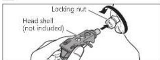
5 Fit the head shell (not included) with the cartridge (not included) into the tone arm. Keep the head shell horizontal and tighten the locking nut.
Preparing the head shell / cartridge (not included) ( 33)
- Be careful not to touch the stylus tip.
Attaching the balance weight

Attach the balance weight to the rear of the tone arm.
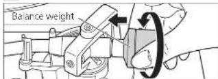
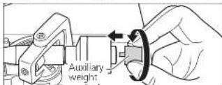
- Attach the included auxiliary weight to the rear of the tone arm according to the weight of your cartridge. For adjustable cartridge weight ranges, see "Applicable cartridge weight range". (≥31)
Note
Using auxiliary weights in tandem may cause the auxiliary weight to come into contact with the dust cover.
The inside of the balance weight is greased.
150
English
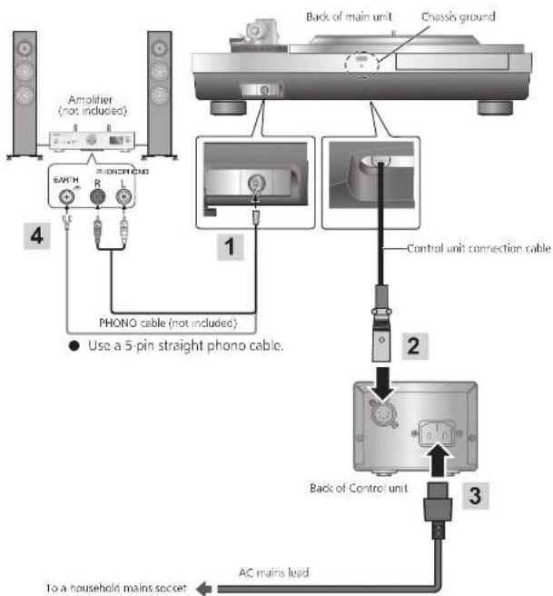
Connections and installation
- Turn off all units and disconnect the AC mains lead from the socket before making any connections.
- Connect the AC mains lead only after all other connections are completed.
- Be sure to connect the PHONO earth lead. Otherwise mains hum may occur
Refer also to the instruction manual of the connected device.
Connecting the output terminal and AC IN terminal / Connecting the control unit
1 Connect a commercially available phone cable to the output terminal.
2 Connect the control unit connection cable by inserting it until it clicks into place.
3 Connect the AC mains lead.
Note
The operation switch does not separate entire unit from mains even if in "OFF" position. Remove the plug from the mains socket if you will not be using the unit for an extended period of time. Place the unit so that the plug can be easily removed.
16 17
English
Chassis ground
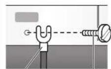
Earth load with lug
M3 screw
Basically, there is no need to connect the chassis ground. If you are concerned about the noise, connect as described below. The noise may decrease though it depends on your environment of use.
Using a commercially available M3 screw, attach an earth lead with lug to the chassis ground.
Connect the earth lead to the earth terminal on the amplifier.
M3 screw 13 mm or less
coarse
thread)
中
less Use a conductive screw.
12 mm or less
1
English
Connections and installation (continued)
Installation
Install the unit on a horizontal surface protected from vibrations. Keep this unit as far as possible from speakers.
Adjusting the height to make the unit horizontal
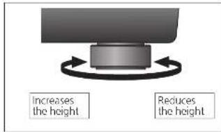
Raise the main unit to turn the insulators and adjust the height.
Attention
Always use two people or more to perform the task.
Do not turn the insulators too far. Doing so may cause them to come off or damage them.
Notes for installation
Always use two people or more to install or move the unit.
Before you move the unit, remove all devices connected and turn off the power supply. Moving the unit with the control unit connected may make it fall off and cause injury.
- Ensure the unit is not exposed to direct sunlight, dust, humidity, and heat from a heating appliance.
- This unit may pick up interference from a radio if there is one nearby.
Keep the unit as far as possible from a radio.
- Do not install the unit on a heat source.
- Avoid a place with large temperature variations.
- Avoid a place with frequent condensation.
- If anti-tip measures are required, consult a contractor. The floor and wall strength need to be checked.
- Avoid an unstable place.
- If the unit ratties when installed, adjust by inserting insulators. (->Left)
- Do not draw the unit forcibly after installation. Doing so may damage the insulator or floor surface.
Do not put an object on the unit. Do not install the unit in a confined space such as a book shelf.
- Install the unit at a position well away from walls or other devices to ensure effective heat radiation from the inside of the unit.
- Make sure the installation location is sufficiently strong to withstand the total weight of the unit and system.
Note that the unit may be damaged by cigarette smoke or moisture from an ultrasonic humidifier.
Condensation
Think of taking out a cold bottle from a refrigerator. If you leave it in a room for a while, dewdrops will form on the bottle surface. This phenomenon is called "condensation."
Rapid temperature change (caused by moving from a warm place to a cold place or vice versa, rapid cooling or heating, or direct exposure to cooled air)
High humidity in a room with much steam, etc.
Rainy season
- Condensation may damage the unit. If it has occurred, turn the unit off and leave it until it adapts to the ambient temperature (approximately 2 to 3 hours).
Insulator attachment
1 Rotate the insulator to remove it from the unit.
Perform the task by placing the packing cushion or the like under the unit.
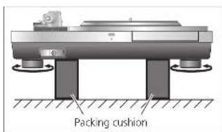
Fix the insulator attachment by screwing it into the insulator.
This makes the insulator lose its cushioning function.

3 Rotate the insulator to attach it to the unit.
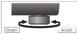
Attention
- Be careful not to lose balance.
Howling may occur as a result of attaching insulator attachments.
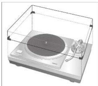
Fit the dust cover
1 While holding the dust cover from both sides, put it in place by aligning its four corners with the four corners of the unit.
- When removing, lift the dust cover straight up.
Attention
Do not use the dust cover if you have a second tone arm connected.
- Remove the dust cover while playing.
19
18 19
English
English
Adjustment
Horizontal balance Stylus pressure
Preparation
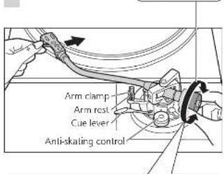
Turn the arm-height control ring to raise the arm to the maximum height. (→ 22)
- Remove the stylus cover, taking care not to damage the stylus, then release the arm clamp.
- Lower the cue level
- Turn the anti-skating
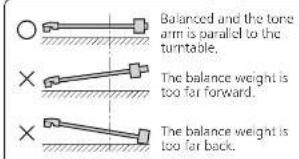
1 Free the tone arm from the arm rest and adjust horizontal balance by turning the balance weight. Hold the tone arm and turn the balance weight in the arrow direction to adjust the balance until the arm is approximately horizontal.
Take care not to allow the stylus tip to touch the turntable mat or main unit.
Preparation
- Return the tone arm to the arm rest and fix it with the arm clamp.
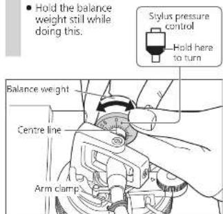
1 Turn the stylus pressure control until "0" comes to the centre line of the rear of the tone arm.
Note
Refer to the user's guide for your stylus for the appropriate stylus pressure.
Anti-skating
2 Turn the balance weight to adjust to the appropriate stylus pressure for the cartridge.
- The stylus pressure control will turn together with the balance weight.
- Turn until the centre line points to the appropriate stylus pressure.
1 Turn the anti-skating control to adjust it to the same value as the stylus pressure control.
Note
For stylus pressures 3 g and above, adjust anti-skiing control to "3".
20 21:
English
20 English
Adjustment (continued)
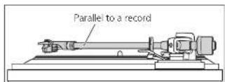
Tone arm height Armlift height
Make this adjustment only if the cartridge you are using makes it necessary.
Preparation
Put a record on the tumtable.
1 Release the arm lock.
Arm lock
2 Adjust the height with the arm-height control ring.
Adjust the arm height until the tone arm becomes parallel to the record.
Turn the arm-height control ring to align the position mark with the index line. 0 to 15mm are marked on the arm height control ring.
Attention
- Selecting a smaller scale mark lowers the arm-height control ring.
- Prevent an object from being caught by the arm-height control ring.
3 After arm height adjustment is finished, lock the tone arm by turning the arm lock knob.
- Be sure to turn the arm lock knob to the end as shown in the figure below. You may need to apply some force to do so.
Remove the stylus cover, taking care not to damage the stylus, then release the arm clamp. Lower the cue lever, rest the stylus on the record and adjust the height control until the tone arm and record are parallel.
Attention
- Be careful not to damage the stylus lip.
Do not use the product with the arm lock released.
For finer adjustment, use a level (not included) to adjust the arm-height so that the cartridge becomes parallel to a record.
Make an adjustment according to your cartridge if necessary.
Preparation
Put a record on the turntable.
- Remove the stylus cover, taking care not to damage the stylus, then release the arm clamp.
- Lift the cue lever and move the tone arm over the record.
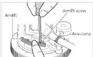
1 Check the armlift height (distance between the stylus tip and record surface). If adjustment is needed, go to step 2.
2 Return the tone arm to the arm rest, clamp it with the arm clamp and while pressing the armlift down with your finger, turn the screw to adjust the height.
- Turning the screw clockwise lowers the armilit.
- Turning the screw anti-clockwise raises the armlift.
22 23
English
29
English
Playing records
Preparation
*1. Put a record (not included) on the turnable
^ 2 Take off the stylus cover (not included) and release the arm clamp.
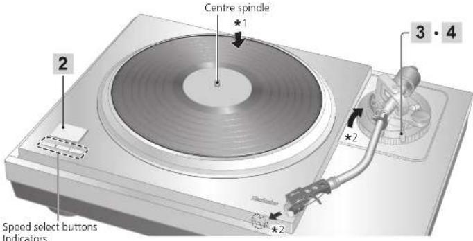
1 Press the power button of the control unit to turn it on.
The speed is automatically set to 33^1 / 3 turns, the [33] indicator lights on the main unit and the turntable speed of [33.33] appears on the display of the control unit.
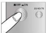
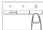
2 Press [START-STOP]. The turntable starts revolving.
![TECHNICS SL1000R - Press [START-STOP]. The turntable starts revolving. - 1](/content/2026/03/463569/images/9bc69d6a1695a5b40af1e5f155cb78fb67a8982c865c855d2366bcfef3786a7b.jpg)
![TECHNICS SL1000R - Press [START-STOP]. The turntable starts revolving. - 2](/content/2026/03/463569/images/b2d394c6c7ac78d93e1e7928ab1c92539af66c0ede9bf9265c78e1a80ddda629.jpg)
Attention
Do not press [START-STOP] when the turntable is removed.
24 25
English
3 Lift the cue lever and move the tone arm over the record.
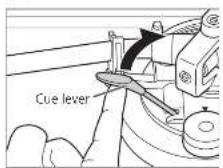
4 Lower the cue lever slowly. The tone arm moves down slowly.

Play starts.
To temporarily stop play
Lift the cue lever.
The stylus lifts off the record.
To start play again, lower the cue lever.
When play finishes
Lift the cue lever, return the tone arm to the arm rest and lower the cue lever.
Press [START-STOP]
The electronic brake gently stops the
turntable
Press the power button of the control unit to turn it off.
Clamp the tone arm with the arm clamp.
Put the stylius cover back on (to protect the stylius lip).
When playing EP records
Press the speed select button [45].
(145) lights.
- Fit the EP record adaptor over the centre spindle.
When playing SP records
Press the speed select button [78] ([78] lights).
When using a record stabilizer (not included)
See the instruction manual of the record stabilizer.
Maximum weight: 1 kg
Note
- Pressing [33/45/78] on the control unit can also change the turntable speed. (≈ 27)

English
Pitch control (fine adjustment to pitch)
1 Press [-] or [+] on the control unit to make adjustment.
The pitch can be set within approximately ± 16% of the currently set turntable speed [33/45/78].
- The current set value appears on the display of the control unit. The display differs depending on the display mode.
(Switching the display mode 27
The turntable speed changes each time the pitch is set while the turntable is rotating.
*Pressing the button increases or decreases the value.
*Holding the button down accelerates the increase or decrease.
- When the display mode is "Turntable speed setting"
When the display mode is "Pitch setting"
26 27
English
To return to the prescribed turntable speed Press [RESET] on the control unit.
The value immediately returns to the prescribed turntable speed. (31/3, 45 or 78.26 rpm)
- The display of the control unit shows the prescribed setting.
The turntable speed becomes the prescribed turntable speed in the turntable speed setting mode and 0.0% in the pitch setting mode.
(Display mode: Turntable speed setting)

Speed selector button indicators of the main unit during pitch control
Blue LED on: Without pitch control (0.0%)
Orange LED on: During pitch control
Note
- The pitch can be set for each turntable speed.
- Turning off the power button cancels the pitch control setting. Turning on the power button again returns the value to the initial setting.
Operation and display of the control unit
Turntable speed setting
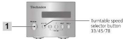
1 Press [33/45/78] on the control unit.
Each time [33/45/78] is pressed, the turntable speed changes in order of "33" → "45" → "78" → "33" → ...
The turntable speed changes each time the pitch is set while the turntable is rotating.
![TECHNICS SL1000R - Press [33/45/78] on the control unit. - 1](/content/2026/03/463569/images/d5ad35e8c9b0cd94948fffcd503c6ba0914293bf5774017882e989fd6f20eca4.jpg)
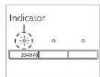
Switching the display mode
Press [DISPLAY] on the control unit.
Each time [DISPLAY] is pressed, the display mode changes in order of "turntable speed setting" "Pitch setting" "Turntable speed measurement" "Turntable speed setting" ...
![TECHNICS SL1000R - Press [DISPLAY] on the control unit. - 1](/content/2026/03/463569/images/2ff1e01e710d1c90087734824e563a513037d6104334b17637668fdd66b3dfb3.jpg)
Turntable speed measurement
The actual turntable speed can be measured in this display mode. Switch the display mode (see above) to enter this mode.
- "rpm" appears after the numerical value.
- "... rpm" appears when the turntable has stopped.

Operation during "Turntable speed measurement"
Operating the buttons as below changes the display mode to "Turntable speed setting" allowing you to make the setting. The display mode returns to "Turntable speed measurement" if no operation is performed within three seconds.
- 12[12 + 12] The pitch can be adjusted. (→ 26)
[RESET]: The value immediately returns to the previously turned able round
[33/45/78]: The turntable speed changes each time the button is pressed.
Note
An averaged value is displayed.
29
English
Operation and display of the control unit(continued)
Display dimmer setting
The display dimmer will be activated if the control unit is not operated for 20 seconds. There are four dimming patterns.
1 On the control unit, hold [RESET] down and press [DISPLAY].
The dimmer setting is displayed.
2 Press [DISPLAY] on the control unit. The setting changes each time [DISPLAY] is pressed. (3Sec below.)
The display returns to the original display if no operation is performed within three seconds.
| Display | Display dimmer when no operation is performed for 20 seconds |
| Display OFF | Brightness is reduced by one level. ⇒ (No operation for further five seconds) ⇒ Brightness is reduced by two levels. ⇒ (No operation for further five seconds) ⇒ Off |
| Dimmer OFF | No dimming (Always on) |
| Dimmer 1 | Brightness is reduced by one level. |
| Dimmer 2 | Brightness is reduced by two levels. |
After setting, brightness is immediately adjusted to the set value. The display is immediately turned off if "Display OFF" is selected.
- Operating a button (any button other than the power button) on the control unit while the dimmer is active returns the display to full brightness.
Note
- The setting is saved. When the power is turned on the next time, the setting when the power was turned off last will be recovered.
28 29
English
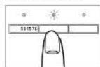
Adjusting the torque to rotate the turntable at a constant speed
Press [START-STOP] and then adjust the torque (rotational force) at five levels to rotate the turntable at a constant speed.
1 On the control unit, hold [RESET] down and press [-] and [+] simultaneously.
The torque setting is displayed.
2 Press [-] or [+] on the control unit to make adjustment.
- Select one of the five levels from "TORQUE1" to "TORQUES". Pressing the button increases or decreases the value.
- Use the table below as a guide.
- The display returns to the original display if no operation is performed within three seconds.
| Display | Torque to rotate at a constant speed |
| TORQUE5 Maximum (Initial setting) | |
| TORQUE4 | |
| TORQUE3 | |
| TORQUE2 | |
| TORQUE1 Minimum | |
Note
- The setting is saved. When the power is turned on the next time, the setting when the power was turned off last will be recovered.
Maintenance
Care of the parts
Thoroughly clean dust off the stylus and record.
Take off the head shell with the cartridge and clean the stylus using a soft brush. Brush from the base to the tip.
Use a record cleaner to keep your records clean.

Wipe the head shell terminals occasionally. Wipe the head shell terminals with a soft cloth and fit the head shell to the tone arm.
Turn the amplifier volume down or turn the amplifier off before fitting or removing the head shell.
Damage to your speakers can occur if the head shell is moved while the volume is turned up.
Cleaning the dust cover and cabinet
Wipe the dust cover and cabinet with a soft cloth.
When dirt is heavy, wring a wet cloth tightly to wipe the dirt, and then wipe it with a soft cloth.
- Do not use solvents including benzene, thinner, alcohol, kitchen detergent, a strong chemical or any other.
Ethical, proper, etc. This might cause the extension to be deformed or the coating to come off.
- Do not wipe the dust cover while playing a record.
This can cause static electricity. This static can cause the tone arm to be attracted towards the dust cover.
■ Moving the unit
Repackage the unit in the packaging it came in, (≈ 12)
Keep the packaging materials after taking out the goods. If you are unsure how the packaging do the
If you no longer have the packaging, do the following:
Take off the turntable and turntable mat and carefully wrap them.
- Remove the head shell and balance weight from the tone arm and carefully wrap them.
- Clamp the tone arm with the arm clamp and tape it in place.
- Carefully wrap the main unit in a blanket or papcr.
WEEE symbol
Disposal of the product outside the EU countries
This symbol is valid within the EU only.
Contact a local governmental office or your dealer to confirm a right manner of disposal.
29
English
Before requesting service, make the below checks. If you are in doubt about some of the check points, or if the remedies indicated in the chart do not solve the problem, contact your dealer.
No power
Is the AC mains lead unplugged in? No, the mains leads are fine for
- Plug the mains lead in himily. (46)
Is the control unit connected with the main unit?
- Insert the control unit connection cable until it clicks. (16)
No indication on the display of the control unit
Is the power plug connected? Insert it firmly. ( 16)
●Is the power on?
Press the power button to turn on the power. (24)
Is the display dimmer activated?
- Operate a button (any button other than the power button) on the control unit. ( 28)
There is power but no sound. Sound is weak
- Are connections to the amplifier/receiver's PHONO terminals correct?
Connect the PHONO cables to the
amplifier's PHONO input terminals. (一 16)
Left and right sounds are reversed
Are the stereo connection cable connections to the amplifier or receiver reversed?
to the amplifier of receiver reveried? Double check all connections. ( 16)
- Are connections of the head shell's lead wires to the cartridge terminals correct?
Double check all connections.
Humming is heard during play
- Are there other appliances or their AC mains lead near the stereo connection cable?
Separate the appliances and their AC mains lead from this unit.
Is the earth lead connected?
Make sure the earth lead is correctly connected. (4-16)
30 31:
English
■ Error code
Occurrence of an error will be notified as necessary on the display of the control unit and with the speed selector button indicators of the main unit.
| Display of the control unit | Measure |
| Unconnected | Check that the control unit is connected with the main unit. (☐ 16) |
| F58F76F17 | Consult your dealer.One of the [33/45/78] speed selector button indicators of the main unit blinks (rapidly or slowly) in orange.Provide the displayed number and the LED's blinking status at the time of consultation. |
Example of the display of the control unit in case of an error
Unconnected
Example of the speed selector button indicators of the main unit in case of an error Flashes in orange.
SpecificationsTroubleshooting guide
| General | |
| Power supply AC 110-240 V, 50/60 Hz | |
| Power consumption | 10 W (Power ON)0.05 W (Power OFF) |
| Dimensions(W×H×D) | <Control unit>110×84×350 mm(4-11/32×3-5/18×13-25/32 inch) |
| <Main unit without dustcover>524×168×392 mm(20-21/32×6-5/8×15-7/16 inch) | |
| <Main unit with dustcover>531×188×399 mm(20-29/32×7-13/32×15-23/32 inch) | |
| Mass | <Control unit>Approx. 2.1 kg (4.7 lbs) |
| <Main unit without dust cover>Approx. 38.0 kg (83.8 lbs) | |
| <Main unit with dust cover>Approx. 40.2 kg (88.7 lbs) | |
| Operatingtemperaturerange | 0 °C to 40 °C(32 °F to 104 °F) |
| Operatinghumidity range | 35 % to 80 % RH(no condensation) |
| Turntable section | |
| Drive method Direct drive | |
| Motor Brushless DC motor | |
| Tumtable Brass andAluminum die-castcombinedDiameter: 323 mm(12-23/32 inch)Mass: Approx. 7.9 kg(17.5 lbs)(including the turntable sheet) | |
| Tumtable speeds 33 1/3, 45 and 78* rpm | |
| Variable rangepitch | +16 % |
| Starting torque 0.39 N·m (4.0 k g·cm)/ 3.47 lb-in | |
| Braking system Electronic brake | |
| Wow and flutter 0.015 % W.R.M.S.(IIS C5521) | |
Tone arm section
Type Universal Static Balance
| Effective length | <Distance from the tone arm rotation axis to the stylus tip> 254 mm (10 in.) |
| <Distance from the tone arm rotation axis to the spindle> 239 mm (9-13/32 inch) | |
| Overhang 15 mm | (19/32 inch) |
| Tracking error angle | Within 1° 48' (at the outer groove of 30 cm (12") record) Within 0° 30' (at the inner groove of 30 cm (12") record) |
| Offset angle 21° | |
| Arm-height adjustment range | 0 - 15 mm |
| Stylus pressure adjustment range | 0 - 4 g (direct reading) |
| Applicable cartridge weight range(Including the head shell and mounting screws) | (Without the auxiliary weight) 15.9 to 19.7 g(With the small auxiliary weight) 18.8 to 23.6 g(With the mid auxiliary weight) 22.5 to 26.3 g(With the big auxiliary weight) |
Terminal section
Output terminal PHONO (DIN Jack) -straight type cable only
Specifications are subject to change without notice.
* The turntable speed will be 78.26 rpm when set to 78 rpm (pitch control 0.0%).
[21]
English
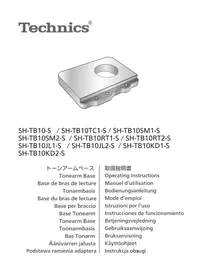
Optional Products
Tonearm base
Consult your dear for optional products.
| Model number | Supported manufacturer | Supported model |
| SH-TB10-S | - | Blank tonearm base* |
| SH-TB10TC1-S Technics EPA-100mk2 | ||
| SH-TB10SM1-S | SME | M2-9R |
| SH-TB10SM2-S M2-12R | ||
| SH-TB10RT1-S | Ortofon | AS-212S |
| RS-212D | ||
| SH-TB10RT2-S | AS-309S | |
| RS-309D | ||
| SH-TB10JL1-S | JELCO | SA-250 |
| SH-TB10JL2-S SA-750L | ||
| SH-TB10KD1-S | IKEDA | IT-345 CR-1 |
| SH-TB10KD2-S IT-407 CR-1 | ||
- The product does not have mounting holes.
Process the product according to your tone arm.
Preparing the head shell / cartridge (not included)
Attaching the cartridge
1 Attach a cartridge (store-bought) tentatively.
Follow the cartridge's instructions to correctly attach it to the head shell, and tighten the screws lightly.
- When playing SP records, use a cartridge for SP records.
- Be careful not to touch the stylus tip.
2 Adjust the overhang. Use the included overhang
The overhang can be adjusted optimally.
32 33
English
34
English
IMPORTANT MISES EN GARDE
Raccordements et installation
Raccordements et installation (suite)
Installation
La lecture commence.
Pour interrompre momentanement la lecture
Raccordements et installation
Raccordements et installation (suite)
Installation
La lecture commence.
In order to prevent damage during shipping some of the equipment has been disassembled. Please check and identify the supplied accessories.
(331/3,45 ether 78,26 rpm)
* Styrenehedens display viser
- Pas pa'ikke at lade pickup'en glide ud at sin places.
Pickup'ens overhaeng kan justeres optimal.
Set pickup-huset den overhaengskabelon.
Overhaengsskabelon
Balansvitken are for langt fram.
Balaansvitken are for langt bak.
Förberedelse
Justering (fortsattning)
Tonarmens hojd Tonarmlyftens hojd
Utfor endastenna justering om den pickup du anvander gocrd nodvandigt.
Förberedelse
Laggcn skiva pa skvtilnken.
1 Frigör tonarmsåt.
2 Justera hojden med justerringen for tonarmshojd.
Justora tonarmons hoid tills tonarmon ar parallell med en skva.
Vrid pa justerringen for tonarmshodj for att rikt in positionsmarket med indexjinen. 0 till 15 mm ar markerade pa justerringen for tonarmshodj.
1ds 120 secondersins fura dimmon
1 Pa styrenheten haller du [Aterstall] nere och trycker pa [DISPLAY].
- Installingen for dimmern visas.
2 Tryck pa [Display] pa styrenheten.
Instaliningen andras varje gang du trycker pa
DISPLAYI
- Visningslagt Atergår till den ursprungiga vyn om ingen operation utfers inom Ure skunder.
Tarrn rnrnnrnnn nannn nn nnnn nnnn nnnn nnnn nnnn nnnn nnnn nnnn nnnn nnnn nnnn nnnn nnnn nnnn nnnn nnnn nnnn nnnn nnnn nnnn nnnn nnnn nnnn nnnn nnnn nnnn nnnn nnnn nnnn nnnn nnnn nnnn nnnn nnnn
Lisälaitteet
Limited Warranty (ONLY FOR U.S.A.)
Technics Products - Limited Warranty
Limited Warranty Coverage (For USA Only)
If your product does not work properly because of a defect in material or workmanship, Penson Corporation of North America (referred to as "the guarantee") will, for the length of the period indicated on the chart below, which starts with the date of original purchase ("warmly period"), at its option either to repair your product with new or refurbished parts. If you notice it with a new or a refurbished equivalent value product, or if you refund your purchase price. The decision to repair, repairs or any part will be made by the guarantee.
| Product or Part Name Part Label | ||
| Technique Network Audio Amplifier | ||
| Technique Music Server | 3 (twos) years | 3 (twos) years |
| Technics CD Steer System | ||
| Technica Turnkey System | ||
During the "Labor" warranty period there will be no charge for labor. During the "Parts" warranty period, there will be no charge for parts. This Limited Warranty excludes both parts and labor for non-rechargeable batteries, intemals, and cosmetic parts (lcbarn). This warranty only applies to products purchased and services in the United States. This warranty is extended only to the original purchaser of a new product which was not sold as "as it is." Mail in Service-Online Repair Requests.
Online Earnings Request
To submit a new repair request one for quie repair status visit our
http://shop.patanotic.com/support
When shipping the unit, carefully pick, include all supplied accessories. Isolated in the Owner's Manual, and send it promptly, adequately buried and poops well in a certain box. When shipping Lithium Ion batteries please visit our Web site at http://shop.panasonic.com/support as Panasonic is committed to providing the most up-to-date information on battery use after qualifying for a new battery. Please order a pristine phone number who you can be tracked. A warranty receipt is required under the United Warranty.
E. REPAIR IS NEDDED DURING THE WARRANTY PERIOD. THE PURCHASER WILL BE REQUIRED TO FURNISH A SALES. RECEIPT/PROOF OF PURCHASE INDICATING DATE OF PURCHASE, AMOUNT PAID AND PLACE OF PURCHASE CUSTOMER WILL BE CHARGED FOR THE REPAIR OF ANY UNIT RECEIVED WITHOUT SUCH PROOF OF PURCHASE.
Limited Warranty Units and Excusions
The warranty ONLY COVERS FAILS due to defects in materials or workmanship, and DOTS N21 COVER normal wear and tear or cosmetic damage. The warranty ALSO DOES NOT COVER damages which occurred in shipment, or failures which are caused by products not supplied by the owner, or failures which result from accidents, musc, abuse, neg cct, misrading, misvaluation, on alteration, faulty insulation, setup adjustment, misuse/instillation of consumer contents, improper maintenance, over fire, lightning damage, modification, introduction of sand, humidity/loids, commercial use such as hotel, office, restaurant, or other business or rental use of the product, or service by anyone other than Factory Service Center or Other Authorized Service, or damage that is attributable to acts of God.
| The model number and serial number of this product can be found on either the back or the bottom of the unit. Please note them in the space provided below and keep for future reference. |
MODELL NUMBER
SL-1000R
THERE ARE NO EXPRESS WARRANTY EXCEPT AS LISTED UNDER "LIMITED WARRANTY COVERAGE". THE WARRANTYOR NOT LIABLE FOR INDICIAL OR CONSEQUENTIAL DAMAGESELATING FROM THE USE OF THIS PRODUCT,ORARISING OUT OF ANY BREACH OF THIS WARRANTY.
As examples, this excludes damages for loss, time, travel to and from the service, loss or damage to media or images, data or other memory or recorded content. The items listed are not exclusive, but for illustration only.
THE EXPRESS WARRANTY INCLUDES ALL REMARKS OF CONTRACTRARITIES, INCLUDING THE WARRANTY OF MERCHANTIABILITY, ARE LIMITED TO THE PERIOD OF THE LIMITED WARRANTY.
Some states do not allow the exclusion or limitation of incidental or consequential damages, or limitations on how long an expired warranty lasts, so the dealers may not apply to you. This warranty gives you specific legal rights and you may also have other rights which vary from state to state. If a problem with this product exceeds during or after the warranty period, you may contact your dealer or Service Center. If the problem is not handled by your salesperson, then write me:
Consumer Affairs Department
Parasitic Corporation of North America
6610000000000000000000000000000000000000000000
PARTS AND SERVICE, WHICH ARE NOT COVERED BY THIS LIMITED WARRANTY, ARE YOUR RESPONSIBILITY.
Shop
Accessories!
for all your Technics gear
Go to
http://shop.pansort.com/support
Get everything you need to get the most out of your Tech Products
Accessories B Parts for your Camera, Phone, A/V, autoclave, TV, Computers & Networking, Personal Care, Home Appliances, Headaches, Batteries, Backups Changes & More
Customer Services Directory
For Products Information, Operating Assistance, and Technical Support, please visit http://www.chip.panama.com/support.
For thecaring or specnimposed ITY 1877 833 885
As at February 2018
Limited Warranty (ONLY FOR CANADA)
Panasonic Canada Inc.
5770 Ambler Drive, Mississauga, Ontario L4W 2T3
TECHNICS PRODUCT -LIMITED WARRANTY
Panasonic Canada Inc. warrants this product to be free from defects in material and workmanship under normal use and for a period as stated below from the date of original purchase agrees In, as its option either (a) repair your product with new or refurbished parts, (b) replace it with a new or a refurbished equivalent value product, or (c) refund your purchase price. The decision to repair, replace or refund will be made by Panasonic Canada Inc.
| Technics Network Audiin Amplifier 3 (three) years parts and labour |
| Technics Music Server 3 (three) years parts and labour |
| Technics CD Stereo System 3 (three) years parts and labour |
| Technics Turntable System 3 (three) years parts and labour |
This warranty is given only to the original purchaser, or the person for whom it was purchased as a gift, of a Technics brand product mentioned above sold by an authorized Panasonic dealer in Canada and purchased and used in Canada, which product was not sold "as is", and which product was delivered to you in new condition in the original packaging
IN ORDER TO BE ELIGIBLE TO RECEIVE WARRANTY SERVICE HEREUNDER, A PURCHASE RECEIPT OR OTHER PROOF OF DATE OF ORIGINAL PURCHASE, SHOWING AMOUNT PAID AND PLACE OF PURCHASE. IS REQUIRED
LIMITATIONS AND EXCLUSIONS
This warranty ONLY COVERS failures due to defects in materials or workmanship, and DOES NOT COVER normal wear and tear or cosmetic damage. The warranty ALSO DOES NOT COVER damages which occurred in shipment, or failures which are caused by products not supplied by Panasonic Canada Inc., or failures which result from accidents, misuse, abuse, neglect, mishandling, misapplication, alteration, faulty installation, set up adjustments, misjudgment of consumer controls, improper maintenance, power line surge, lightning damage, modification, introduction of sand, humidity or liquids, commercial use such as hotel, office, restaurant, or other business or rental use of the product, or service by anyone other than an Authorized Servicer, or damage that is attributable to acts of God.
Dry cell batteries are also excluded from coverage under this warranty.
THIS EXPRESSLY, LIMITED WARRANTY IS IN LEU OF ALL OTHER WARRANTYES, EXPRESSLY OR IMplied, INCLUDING ANY IMPLIED WARRANTY OF MERCHANT ABILITIES AND FITNESS FOR A PARTICULAR PURPOSE IN NO EVENT WILL PANASONIC CANADA INC. BE LAIBLE FOR ANY SPECIAL, INDIRECT OR CONSEQUENTIAL DAMAGES RESULTING FROM THE USE OF THIS PRODUCT OR ASRISING OUT OF ANY BREACH OF ANY EXPRESS OR IMplied WARRANTY. (As examples, this warranty excludes damages for lost time, travel to and from the Authorized Servicer, loss of or damage to media or images, data or other memory or recorded content. This list of items is not exhaustive, but for illustration only.)
In certain instances, some jurisdictions do not allow the exclusion or limitation of incidental or consequential damages, or the exclusion of implied warranties, so the above limitations and exclusions may not be applicable. This warranty gives you specific legal rights and you may have other rights which vary depending on your province or territory.
WARRANTY SERVICE
For product operation, repairs and information assistance, please visit our Support page on.
www.eanasonic.ca/english/support
IF YOU SHIP THE PRODUCT TO A SERVICENTRE
Carefully pack and send prepaid, adequately insured and preferably in the original carton.
include details of the defect claimed, and proof of date of original purchase.
Certificat de garantie limite (SEULEMENT POUR LE CANADA)
Panasonic Canada Inc.
5770, Ambler Drive, Mississauga (Ontario) L4W 2T3
PRODUIT TECHNICS - GARANTIE LIMITEE


- For the U.S.A.
- For Canada / Pour le Canada
- For the United Kingdom and Ireland
- For Continental Europe
- SL-1000R
- Delivering the Ultimate Emotive Musical Experience to All
- For the U.S.A. and Canada
- For the United Kingdom and Ireland customers
- Features
- Coreless direct drive motor for smooth and accurate rotation
- Three-layer turntable for stable rotation
- High-sensitivity tone arm for accurate reading of record grooves
- Thorough anti-vibration design with the five-layer cabinet and insulator
- Seeking for ideal sound with excellent system scalability
- Special control unit that can eliminate unwanted noise interference with the main unit
- Table of contentsIntroduction
- Before use
- Getting started
- Blaying back
- Maintenance
- Safety precautions
- Warning
- Unit
- AC mains lead
- Caution
- Placement
- 07:
- English
- Caution for AC Mains Lead
- How to replace the fuse
- Disposal of Old Equipment
- Only for European Union and
- countries with recycling systems
- IMPORTANT SAFETY INSTRUCTIONS
- IMPORTANT SAFETY INSTRUCTIONS (continued)
- THE FOLLOWING APPLIES ONLY IN THE U.S.A. FCC Note:
- THE FOLLOWING APPLIES ONLY IN CANADA. CAN ICES-3(B)/NMB-3(B)
- Accessories
- Parts Name
- Unpacking and preparation
- Notes for taking out the goods from the package box and transporting
- Attention
- Putting the player together
- 15
- Fitting the turntable
- Fitting the turntable mat
- Attaching the head shell
- Attaching the balance weight
- Note
- Connections and installation
- Connecting the output terminal and AC IN terminal / Connecting the control unit
- Connections and installation (continued)
- Installation
- Notes for installation
- Condensation
- Insulator attachment
- Fit the dust cover
- Adjustment
- Horizontal balance Stylus pressure
- Preparation
- Anti-skating
- Adjustment (continued)
- Tone arm height Armlift height
- Release the arm lock.
- Adjust the height with the arm-height control ring.
- After arm height adjustment is finished, lock the tone arm by turning the arm lock knob.
- Playing records
- Press the power button of the control unit to turn it on.
- Press [START-STOP]. The turntable starts revolving.
- Lift the cue lever and move the tone arm over the record.
- Lower the cue lever slowly. The tone arm moves down slowly.
- To temporarily stop play
- When play finishes
- When playing EP records
- When playing SP records
- When using a record stabilizer (not included)
- Pitch control (fine adjustment to pitch)
- Operation and display of the control unit
- Turntable speed setting
- Press [33/45/78] on the control unit.
- Switching the display mode
- Press [DISPLAY] on the control unit.
- Turntable speed measurement
- Operation and display of the control unit(continued)
- Display dimmer setting
- 29
- Adjusting the torque to rotate the turntable at a constant speed
- Care of the parts
- Cleaning the dust cover and cabinet
- ■ Moving the unit
- WEEE symbol
- No power
- No indication on the display of the control unit
- There is power but no sound. Sound is weak
- Left and right sounds are reversed
- Humming is heard during play
- ■ Error code
- Unconnected
- SpecificationsTroubleshooting guide
- Tone arm section
- Terminal section
- Optional Products
- Tonearm base
- Preparing the head shell / cartridge (not included)
- Attaching the cartridge
- Attach a cartridge (store-bought) tentatively.
- Adjust the overhang. Use the included overhang
- IMPORTANT MISES EN GARDE
- Raccordements et installation
- Raccordements et installation (suite)
- Pour interrompre momentanement la lecture
- Förberedelse
- Justering (fortsattning)
- Tonarmens hojd Tonarmlyftens hojd
- Frigör tonarmsåt.
- Justera hojden med justerringen for tonarmshojd.
- Lisälaitteet
- Limited Warranty (ONLY FOR U.S.A.)
- Technics Products - Limited Warranty
- Limited Warranty Coverage (For USA Only)
- Online Earnings Request
- Limited Warranty Units and Excusions
- Shop
- Accessories!
- Limited Warranty (ONLY FOR CANADA)
- TECHNICS PRODUCT -LIMITED WARRANTY
- LIMITATIONS AND EXCLUSIONS
- WARRANTY SERVICE
- Certificat de garantie limite (SEULEMENT POUR LE CANADA)
- PRODUIT TECHNICS - GARANTIE LIMITEE
Brand : TECHNICS
Model : SL1000R
Category : Turntable