
AX396 - Home cinema amp YAMAHA - Free user manual and instructions
Find the device manual for free AX396 YAMAHA in PDF.
| Brand | YAMAHA |
| Model | AX396 |
| Category | Home theater amplifier |
| Product type | Integrated stereo amplifier |
| Dimensions (W x H x D) | 435 x 151 x 391 mm |
| Weight | 8.7 kg |
| Power supply | AC 230 V, 50 Hz (European model) |
| Power consumption | Approx. 150 W |
| RMS output power | 60 W + 60 W (8 Ω, 20 Hz - 20 kHz, 0.019 % THD) |
| Total harmonic distortion | 0.019 % (20 Hz - 20 kHz, half power) |
| Frequency response | 20 Hz - 20 kHz ±0.5 dB |
| Signal-to-noise ratio (CD/DVD, DIRECT AMP ON) | 110 dB (IHF A-network) |
| Input sensitivity (CD/DVD) | 150 mV / 47 kΩ |
| Input sensitivity (PHONO) | 2.5 mV / 47 kΩ |
| Recommended speaker impedance | 4 Ω minimum (1 pair), 8 Ω minimum (2 pairs) - see impedance selector |
| Switched AC outlets | 3 outlets, total max. 100 W |
| Main functions | Input selector, tone controls (Bass/Treble), balance, loudness compensation, CD/DVD Direct AMP, Tape Monitor, speaker selector A/B, headphone jack, remote control |
| Maintenance | Clean with a dry, clean cloth. Do not use chemical solvents. |
| Safety | Do not open the casing. Disconnect during thunderstorms or extended inactivity. Observe the specified voltage. |
| Included accessories | Remote control, batteries (AA, R6, UM-3) |
Frequently Asked Questions - AX396 YAMAHA
User questions about AX396 YAMAHA
0 question about this device. Answer the ones you know or ask your own.
Ask a new question about this device
Download the instructions for your Home cinema amp in PDF format for free! Find your manual AX396 - YAMAHA and take your electronic device back in hand. On this page are published all the documents necessary for the use of your device. AX396 by YAMAHA.
USER MANUAL AX396 YAMAHA
UNPACKING After unpacking, check that the following items are contained.
Opening and closing the front cover
Close the front cover whenever the controls inside the panel are not used.
To open the front cover
To close the front cover
85W + 85W (8Ω) RMS Output Power, 0.019% THD, 20–20,000 Hz
AX-396
60W + 60W (8Ω) RMS Output Power, 0.019% THD, 20-20,000 Hz
- Highly Dynamic Power, Low Impedance Drive Capability
- Continuously Variable LOUDNESS Control
CD/DVD DIRECT AMP Switch Used to Reproduce the Purest CD and DVD Sound
Remote Control Capability
AX-496 only
REC OUT Selector Independent of Input Source Selection
PURE DIRECT Switch Used to Reproduce the Purest Source Sound
CONTENTS
UNPACKING Inside of Front Cover
FEATURES 1
CAUTION 2
NOTES ABOUT THE REMOTE CONTROL 3
CONNECTIONS 4
CONTROLS AND THEIR FUNCTIONS 6
OPERATION 9
TROUBLESHOOTING 13
SPECIFICATIONS. 14
- To assure the finest performance, please read this manual carefully. Keep it in a safe place for future reference.
- Install this unit in a cool, dry, clean place - away from windows, heat sources, sources of excessive vibration, dust, moisture and cold. Avoid sources of humming (transformers, motors). To prevent fire or electrical shock, do not expose the unit to rain or water.
- Never open the cabinet. If something drops into the set, contact your dealer.
- Do not use force on switches, controls or connection wires. When moving the unit, first disconnect the power plug and the wires connected to other equipments. Never pull the wires themselves.
- The openings on the unit cover assure proper ventilation of the unit. If these openings are obstructed, the temperature inside the unit will rise rapidly; therefore, avoid placing objects against these openings. Install the unit in a well-ventilated area to prevent fire or damage. Be sure to allow a space of at least 20~cm behind, 20 cm on both sides and 30~cm above the top panel of the unit to prevent fire or damage.
- The voltage used must be the same as that specified on this unit. Using this unit with a higher voltage than specified is dangerous and may result in fire or other accidents. YAMAHA will not be held responsible for any damage resulting from use of this unit with a voltage other than specified.
- Always set the VOLUME control to " before starting the audio source play. Increase the volume gradually to an appropriate level after the play has been started.
- Do not attempt to clean the unit with chemical solvents as this might damage the finish. Use a clean, dry cloth.
- Be sure to read the "TROUBLESHOOTING" section regarding common operating errors before concluding that the unit is faulty.
- When not planning to use this unit for a long period (ie., vacation, etc.), disconnect the AC power plug from the wall outlet.
- To prevent lightning damage, disconnect the AC power plug when there is an electric storm.
- Grounding or polarization - Precautions should be taken so that the grounding or polarization of an appliance is not defeated.
- Do not connect any audio equipment to the AC outlet on the rear panel if the equipment requires more power than the outlet is rated to provide.
For U.K. customers
If the socket outlets in the home are not suitable for the plug supplied with this appliance, it should be cut off and an appropriate 3 pin plug fitted. For details, refer to the instructions described below.
Note: The plug severed from the mains lead must be destroyed, as a plug with bared flexible cord is hazardous if engaged in a live socket outlet.
SPECIAL INSTRUCTIONS FOR U.K. MODEL
IMPORTANT:
THE WIRES IN MAINS LEAD ARE COLOURED IN ACCORDANCE WITH THE FOLLOWING CODE:
Blue: NEUTRAL
Brown: LIVE
As the colours of the wires in the mains lead of this apparatus may not correspond with the coloured markings identifying the terminals in your plug, proceed as follows: The wire which is coloured BLUE must be connected to the terminal which is marked with the letter N or coloured BLACK. The wire which is coloured BROWN must be connected to the terminal which is marked with the letter L or coloured RED. Making sure that neither core is connected to the earth terminal of the three pin plug.
When this unit is turned off by pressing the STANDBY/ON switch on the front panel or the remote control, the STANDBY indicator on the front panel lights up. This state is called the standby mode. In this mode, this unit is designed to consume a small amount of power. This unit's power supply cannot be completely cut off from the AC line until the POWER switch on the front panel is set in the OFF position or the AC power cord is disconnected.
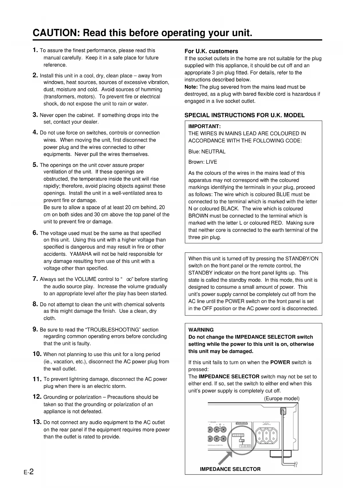
WARNING
Do not change the IMPEDANCE SELECTOR switch setting while the power to this unit is on, otherwise this unit may be damaged.
If this unit fails to turn on when the POWER switch is pressed:
The IMPEDANCE SELECTOR switch may not be set to either end. If so, set the switch to either end when this unit's power supply is completely cut off.
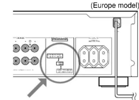
IMPEDANCE SELECTOR
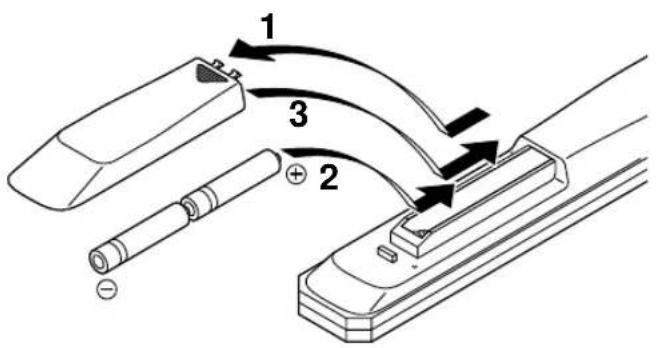
Battery installation
Since the remote control will be used for many of this unit's control operations, you should begin by installing the supplied batteries.
- Turn the remote control over and remove the battery compartment cover by sliding it in the direction of the arrow.
- Insert the batteries (AA, R6, UM-3 type) according to the polarity markings on the inside of the battery compartment.
- Close the battery compartment cover.
Battery replacement
If you notice that the remote control must be used closer to the main unit, the batteries are weak. Replace both batteries with new ones.
Notes
- Use AA, R6, UM-3 batteries.
- Be sure the polarities are correct. (See the illustration inside the battery compartment.)
- Remove the batteries if the remote control is not used for an extended period of time.
- If batteries leak, dispose of them immediately. Avoid touching the leaked material and contact with clothing, etc. Clean the battery compartment thoroughly before installing new batteries.
Remote control operation range
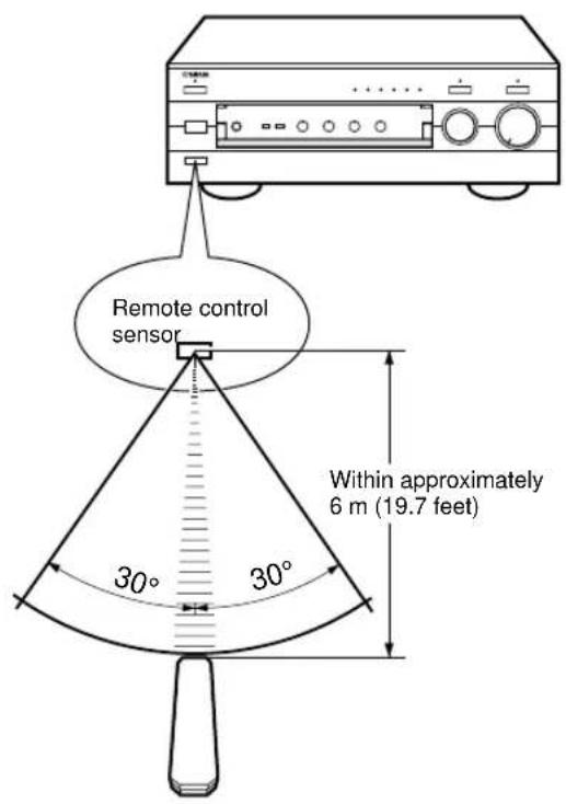
Notes
- The area between the remote control and the main unit must be clear of large obstacles.
- Do not expose the remote control sensor to strong lighting, in particular, an inverter type fluorescent lamp; otherwise, the remote control may not work properly. If necessary, position the main unit away from direct lighting.
CONNECTIONS
Caution: Plug in this unit and other components after all connections are completed.
- All connections must be correct, that is to say L (left) to L, R (right) to R, “+” to “+” and “-” to “-”. Also refer to the owner's manual for each of your components.
- Use RCA type pin plug cables for audio/video units except speakers.
- The output (or input) terminals of YAMAHA audio/video units numbered 1, 2, 3, 4, etc. on the rear panel must be connected to the same-numbered terminals of this unit.
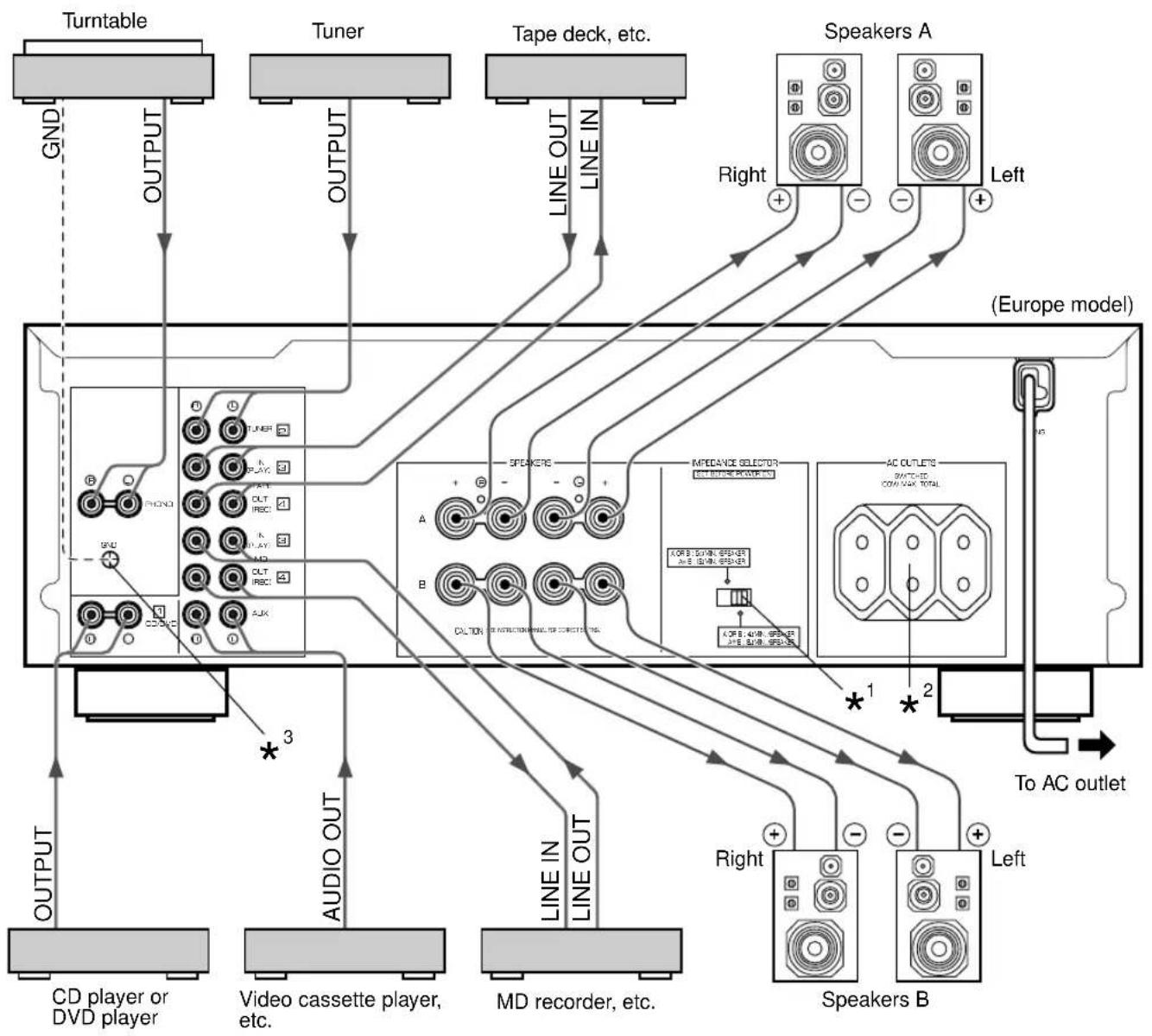
^1,^2,^3 Refer to page 5 for descriptions.
Indicates the direction of signals.
Connecting speakers
Connect the SPEAKERS terminals to your speakers with the wire with the proper gauge (keep it as short as possible). If the connections are faulty, no sound will be heard from the speakers. Make sure that the + and - polarity markings of the speaker wires are observed and set correctly. If these wires are reversed, the sound will be unnatural and lack bass.
Caution
Do not let the bare speaker wires touch each other or any metal part of this unit. This could damage this unit or the speakers, or both.
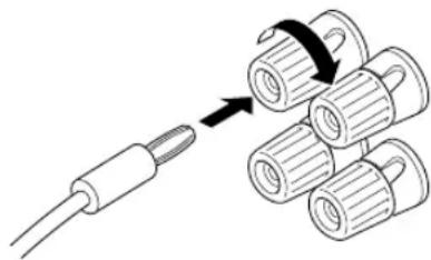
How to Connect:
Red: positive (+) Black: negative (-)
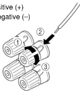
① Loosen the knob.
② Insert the bare wire.
[Remove approx. 10mm (3 / 8^ ) insulation from the speaker wires.]
③ Tighten the knob and secure the wire.
Rear panel parts
IMPEDANCE SELECTOR switch\*
WARNING
Do not change the IMPEDANCE SELECTOR switch setting while the power to this unit is on, otherwise this unit may be damaged.
If this unit fails to turn on when the POWER switch is pressed:
The IMPEDANCE SELECTOR switch may not be set to either end. If so, set the switch to either end when this unit's power supply is completely cut off.
Select the position whose requirements your speaker system meets.
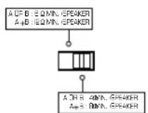
(Right position)
If you use one pair of speakers, the impedance of each speaker must be 4 or higher.
If you use two pairs of speakers, the impedance of each speaker must be 8 or higher.
(Left position)
If you use one pair of speakers, the impedance of each speaker must be 6 or higher.
If you use two pairs of speakers, the impedance of each speaker must be 12 or higher.
- One or two speaker systems can be connected to this unit. If you use only one speaker system, connect it to either the SPEAKERS A or B terminals.
- Use speakers with the specified impedance shown on the rear of this unit.
AC OUTLET(S) (SWITCHED) ^2
(Europe, China and General models)
3 SWITCHED OUTLETS
(U.K. and Australia models). 1 SWITCHED OUTLET
Use these to connect the power cords of your components to this unit.
The power to the SWITCHED outlets is controlled by this unit's POWER or STANDBY/ON switch. These outlets will supply power to any connected unit whenever this unit is turned on.
The maximum power (total power consumption of components) that can be connected to the SWITCHED AC OUTLETS is 100W.
GND terminal (For turntable use) ^3
Connecting the ground wire of the turntable to the GND terminal will normally minimize hum, but in some cases better results may be obtained with the ground wire disconnected.
CONTROLS AND THEIR FUNCTIONS
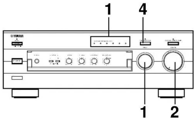
FRONT PANEL
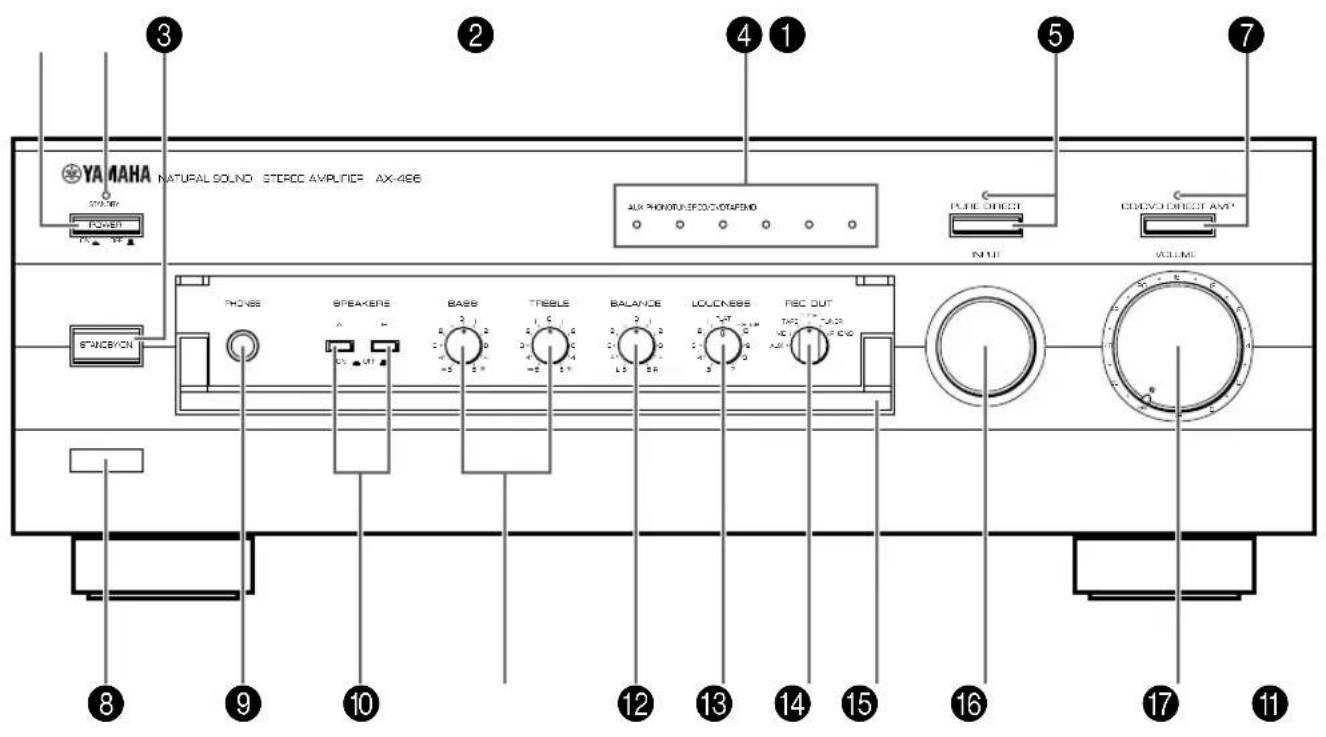
AX-496
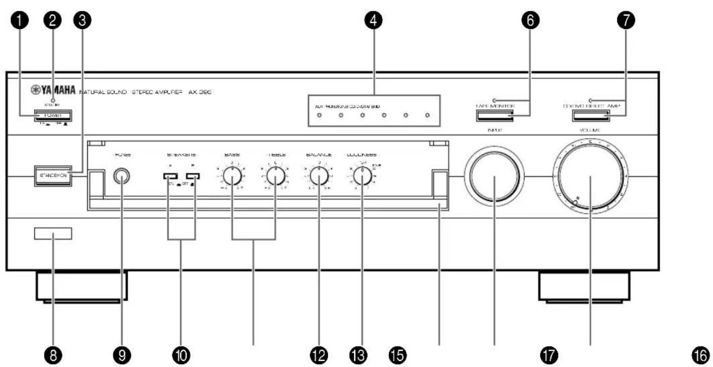
AX-396

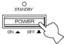
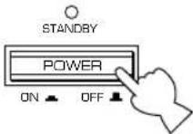
POWER
Press this switch inward (ON) to use this unit. In this state, you can turn on this unit or turn this unit in the standby mode by pressing STANDBY/ON. Press this switch to release it outward (OFF) to completely cut off this unit's power supply from the AC line.

STANDBY indicator
Lights up only while this unit is in the standby mode.

STANDBY/ON
Press this switch to turn on the power. Press again to set this unit in the standby mode.
- This switch can be used only when POWER is set in the ON position.
Standby mode
This unit is still using a small amount of power in this mode in order to be ready to receive infrared-signals from the remote control.

Input source indicators
The indicator of the currently selected input source lights up.

PURE DIRECT and indicato AX-496 on
Press this switch, and the indicator above it lights up.
You can listen to a source in the purest sound with this function. (Refer to page 12 for details.)
Press this switch again to cancel this function.

TAPE MONITOR and indicate AX-396 or
Press this switch to turn on the indicator above it. You can listen to the sound played on the tape deck connected to the TAPE terminals on the rear of this unit. When the tape deck is used for recording, you can also monitor the sound being recorded.
-
To listen to the source selected with the INPUT selector, press this switch again to turn off the indicator.
-
When this function is on (the indicator is illuminated), the tape deck (TAPE) cannot be selected with the INPUT selector.
-
When the tape deck (TAPE) is selected with the INPUT selector, this function will not turn on even if TAPE MONITOR is pressed.

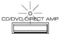
CD/DVD DIRECT AMP and indicator
Press this switch, and the indicator above it lights up. You can listen to a CD or DVD source in the purest sound with this function. (Refer to page 12 for details.) Press this switch again to cancel this function.

Remote control sensor
Receives signals from the remote control.
PHONES

PHONES jack
When you listen with headphones, connect the headphones to the PHONES jack and set both SPEAKERS A and B switches to the OFF position.


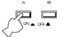
SPEAKERS
Press the switch A or B (or both) inward (ON) for the speakers you will use. Press and release the switch outward (OFF) for the speakers you do not use.

Tone controls
BASS
Rotate this knob to increase or decrease the low frequency response. The 0 position produces a flat response.
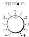
TREBLE
Rotate this knob to increase or decrease the high frequency response. The 0 position produces a flat response.

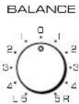
BALANCE
The balance of the output volume to the left and right speakers can be adjusted to compensate for sound imbalances caused by the speaker location or listening room conditions.

LOUDNESS
Used to compensate for the human ears' loss of sensitivity to high and low-frequency ranges at low volume. (Refer to page 12 for details.)

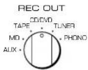
REC OUT select AX-496 on
Rotate this knob to select the source for recording to an MD recorder or tape deck. This setting is independent of the INPUT selector setting, so this function allows you to record the selected source while listening to another source.

Front cover
Refer to inside of the front cover on how to open and close the front cover.

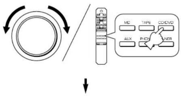
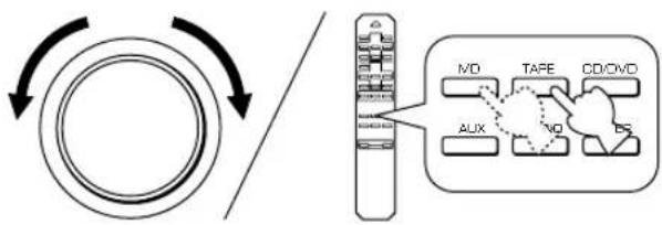
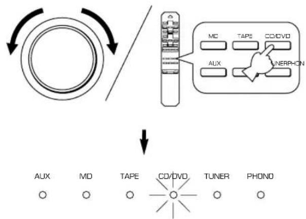
INPUT selector
Turn this knob to select the input source. The selected source will be shown by the lighting of corresponding input source indicator.

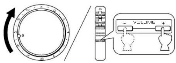
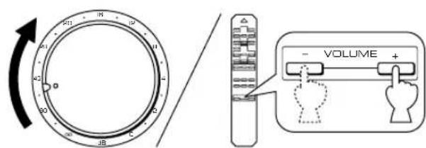
VOLUME
Turn this knob to raise or lower the volume level. (The REC OUT level is not affected.)
REMOTE CONTROL
The remote control is designed to control the most commonly used functions of the main unit. If you have a YAMAHA CD player, tuner, tape deck, etc. with remote control compatibility, this remote control will also control their various functions.
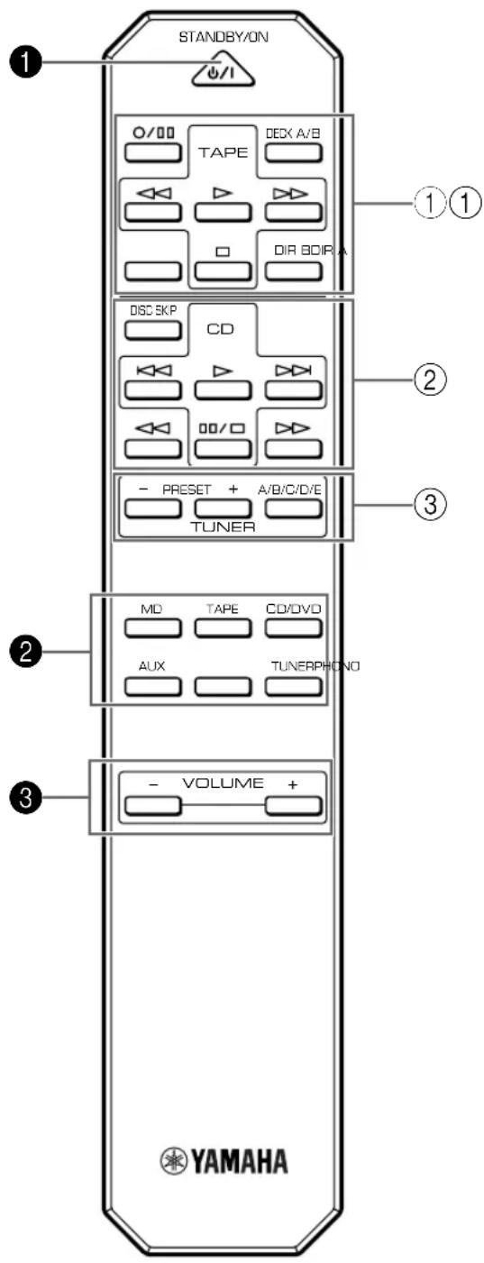
For Control of This Unit
1 STANDBY/ON
Press this key to turn on this unit or turn it into the standby mode.
This key can be used only when the POWER switch on the main unit is set in the ON position.
Standby mode In this state, this unit consumes a very small quantity of power to receive infrared-signals from the remote control.
Input selector keys
Press a key to select the input source.
3 VOLUME + / -
Press these keys to increase or decrease the volume.
For Control of Other Components
Note
The functions of the keys to control other YAMAHA components are the same as the corresponding keys on those components. Refer to those components' instruction manuals for details.
① Tape deck keys
These keys control tape decks.
DIR A, B and A/B apply only to double cassette tape decks.
* Pressing DIR A will reverse the tape direction on a single cassette tape deck with the automatic reverse function.
CD player keys
These keys control compact disc players.
* DISC SKIP is used for disc changers only.
③ Tuner keys
These keys control tuners.
PRESET +: Press this key to select the next preset station number.
PRESET-:Press this key to select the previous preset station number.
A/B/C/D/E: Press this key to select the group (A-E) of preset station numbers.
OPERATION
Playing a source

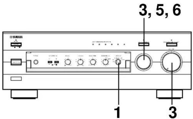
1
Set to the "oo" position.
2
Press POWER inward (ON).
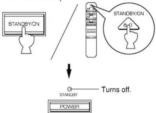
3
If the STANDBY indicator is illuminated, press STANDBY/ON to turn on the power. (The STANDBY indicator turns off.)
4 Select the desired input source.
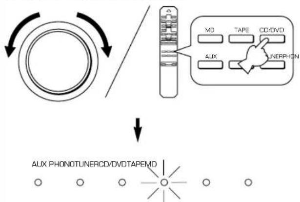
The indicator of the selected source lights up.
5
Select speakers A or B.
SPEAKERS
- Both speakers A and B can be selected.
- Be sure that the IMPEDANCE SELECTOR switch is correctly set as explained on page 5.
- If you listen with headphones, press both switches to release them outward (OFF).
6
Play the source.
7
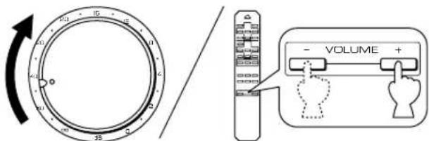
Adjust the output level.
8
Adjust the tonal quality by using the BASS, TREBLE, BALANCE, LOUDNESS controls or the CD/DVD DIRECT AMP switch (or PURE DIRECT switch for AX-496 only). (Refer to page 12).
AX-396 only
If the TAPE MONITOR indicator is illuminated when you listen to a source, press TAPE MONITOR to turn off the TAPE MONITOR indicator.
When you finish using this unit
Press STANDBY/ON again to set this unit in the standby mode. (The STANDBY indicator lights up.)
To completely cut off this unit's power supply from the AC line
Press POWER to release it outward (OFF).
Recording a source to tape (or MD)

1 Select the source you want to record.
2 Play the source.
3 Select the source with the INPUT selector and adjust VOLUME to check the sound output.
4 Begin recording on the tape deck (or MD recorder).
5 The sound of the recording can be monitored by selecting the tape deck (or MD recorder) with the INPUT selector.
6 Listening to another source by selecting it with the INPUT selector will not affect the recording.
AX-396
1 Select the source you want to record.
2 Play the source and then turn VOLUME up to check the sound output.
3 Begin recording on the tape deck (or MD recorder).
4 If the tape deck is used for recording, you can monitor the sound of recording. To monitor the sound of recording, light up the TAPE MONITOR indicator by pressing TAPE MONITOR.

Note
Turn off the TAPE MONITOR indicator when the recording is finished by pressing TAPE MONITOR.
Notes on recording
- The VOLUME, BASS, TREBLE, BALANCE, LOUDNESS controls and CD/DVD DIRECT AMP switch (and PURE DIRECT switch for AX-496 only) have no effect on the material being recorded.
- Please check the copyright laws in your country to record from records, compact discs, radio, etc. Recording of copyright material may infringe on copyright laws.
Sound control
Adjusting the BALANCE control
Adjust the balance of the output volume to the left and right speakers to compensate for sound imbalance caused by speaker location or listening room conditions.
Using the CD/DVD DIRECT AMP switch
You can enjoy the purest possible sound from your CD or DVD player by pressing this switch. The indicator above it lights up. With this function on, input signals from the CD or DVD player are sent directly to the built-in special amplifier for CD/DVD bypassing the INPUT selector, the BASS, TREBLE, BALANCE and LOUDNESS controls (and the TAPE MONITOR switch for AX-396 only), and then sent to the power amplifier. This signal routing reproduces the purest sound eliminating any alterations to the CD or DVD signals.
Using the PURE DIRECT switch
AX-496 only
You can enjoy the purest possible sound from your audio sources by pressing this switch. The indicator above this switch lights up. With this function on, the audio signals bypass the BASS, TREBLE, BALANCE and LOUDNESS controls, thus eliminating any alterations to the audio signals.

Note
If both the CD/DVD DIRECT AMP and PURE DIRECT switches are on, only the CD/DVD DIRECT AMP switch will function.
Adjusting the BASS and TREBLE controls
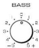
BASS: Turn this knob clockwise to increase (or counterclockwise to decrease) the low frequency response.
TREBLE: Turn this knob clockwise to increase (or counter clockwise to decrease) the high frequency response.
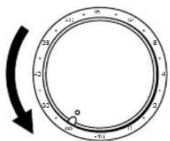
Adjusting the continuously variable LOUDNESS control
This control compensates for the human ears' loss of sensitivity to high and low-frequency ranges at low volume. This control is adjustable to retain full tonal range at any volume level.
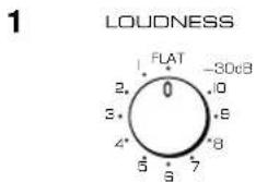
Set to the "FLAT" position.

Set to the loudest listening level that you would listen to.
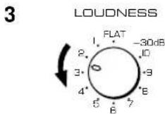
Turn until the desired volume is obtained.
WARNING
If the CD/DVD DIRECT AMP switch (or PURE DIRECT switch for AX-496 only) is pressed to turn it on with the LOUDNESS control set at a certain level, the sound will suddenly increase and may damage your ears or the speakers. (The LOUDNESS control function may be bypassed.) For this reason, be sure to press the CD/DVD DIRECT AMP switch (or PURE DIRECT switch for AX-496 only) after lowering the volume or after checking that the LOUDNESS control is properly set.
Refer to the chart below when this unit does not function properly. If the problem you are experiencing is not listed below or if the instructions given below do not help, disconnect the power cord and contact your authorized YAMAHA dealer or service center.
| Problem | Cause | What to Do |
| The unit cannot be turned on or turns off suddenly soon after the power is turned on. | Power cord is not plugged in nor completely inserted. | Firmly plug in the power cord. |
| The IMPEDANCE SELECTOR switch on the rear panel is not set to either end. | Set the switch to either end when this unit is off. | |
| This unit does not work normally. | There is an influence of strong external noise (lightning, excessive static electricity, etc.) or a misoperation on this unit while using this unit. | Turn off this unit by pressing the POWER switch. After about 30 seconds have passed, turn on this unit and operate this unit again. |
| No sound. | Incorrect output cord connections. | Connect the cords properly. If the problem persists, the cords may be defective. |
| Appropriate input source is not selected. | Select an appropriate input source with the INPUT selector. | |
| The SPEAKERS switches are not set properly. | Set the corresponding SPEAKERS switch to the ON position. | |
| Speaker connections are not secure. | Secure the connections. | |
| The sound suddenly goes off. | The protection circuit has been activated because of short circuit etc. | Turn off this unit by pressing the POWER switch, and then turn this unit on to reset the protection circuit. |
| Only one of the speakers produces the sound. | Incorrect setting of the BALANCE control. | Adjust it to the appropriate position. |
| Incorrect cord connections. | Connect the cords properly. If the problem persists, the cords may be defective. | |
| There is a lack of bass and no ambience. | The + and - wires are connected in reverse at the amplifier or speakers. | Connect the speaker wires in the correct phase (+ and -). |
| Sound “hums”. | Incorrect cord connections. | Firmly connect the audio plugs. If the problem persists, the cords may be defective. |
| No connection from the turntable to the GND terminal. | Make the GND connection between the turntable and this unit. | |
| The volume level is low while playing a record. | The record is being played on a turntable with an MC cartridge. | The turntable should be connected to this unit through the MC head amplifier. |
| The volume level cannot be increased, or sound is distorted. | The component connected to the TAPE OUT or MD OUT terminals of this unit is turned off. | Turn on the power to the component. |
| The sound is degraded when listening with the headphones connected to the compact disc player or tape deck that are connected with this unit. | This unit is turned off or in the standby mode. | Turn on the power to this unit. |
| Sound level is low. | The LOUDNESS control is functioning. | Set the LOUDNESS control to the FLAT position. |
| The input source cannot be changed, though the INPUT selector is turned. | The CD/DVD DIRECT AMP switch is ON. | Switch off the CD/DVD DIRECT AMP switch. |
| Using the BASS, TREBLE, BALANCE and LOUDNESS controls does not affect the tone. | The CD/DVD DIRECT AMP switch (or PURE DIRECT switch for AX-496 only) is ON. | The CD/DVD DIRECT AMP switch (or PURE DIRECT switch for AX-496 only) must be switched OFF to use those controls. |
| The remote control does not work. | The batteries of this remote control are weak. | Replace the batteries with new ones. |
| The remote control does not function properly. | Wrong distance or angle. | The remote control will function from a maximum range of 6 meters and no more than 30 degrees off-axis from the front panel. |
| Direct sunlight or lighting (of an inverter type fluorescent lamp etc.) is striking the remote control sensor of the main unit. | Reposition of the main unit. |
Power Section
Minimum RMS Output Power
8Ω, 20 Hz to 20 kHz, 0.019% THD
Maximum Output Power (EIAJ)
(1 kHz, 10% THD)
8/6Ω 130/150W
6Ω 110W
Dynamic Power (IHF)
8/6/4/2Ω
DIN Standard Output Power
(4Ω, 1 kHz, 0.7% THD)
IEC Output Power (8Ω, 1 kHz, 0.019% THD)
Power Band Width
8Ω, Half power, 0.04% THD. 10 Hz to 50 kHz
Damping Factor
8Ω, 20 Hz to 20 kHz 240
Frequency Response 20 Hz to 20 kHz ± 0.5 dB
Total Harmonic Distortion (20 Hz to 20 kHz)
CD/DVD to SP OUT (8Ω, Half power) 0.008%
Signal-to-Noise Ratio (IHF-A Network)
CD/DVD (Input Shorted, CD/DVD DIRECT AMP: ON)
110 dB
PHONO (Input Shorted) 88 dB
Residual Noise (IHF-A Network)
CD/DVD DIRECT AMP: ON. 35 V
Control Section
Input Sensitivity/Impedance
CD/DVD, etc. 150 mV/47 kΩ
PHONO 2.5 mV/47 kΩ
Output Level
REC OUT 150 mV/1.6 kΩ
Headphone Output. 0.25V/680Ω
Channel Separation (1 kHz/10 kHz)
CD/DVD (Input 5.1 kΩ Terminated) 65 dB/50 dB
Tone Control Characteristics
BASS. ±10 dB (20 Hz)
TREBLE. ±10 dB (20 kHz)
Continuous LOUDNESS Control
Attenuation -30 dB (1 kHz)
General
Power Supply
[Europe and U.K. models] AC 230V, 50 Hz
[Australia model] AC 240V, 50 Hz
[China model] AC 220V, 50 Hz
[General model] AC 110/120/220/240V, 60/50 Hz
Power Consumption
AC Outlets
3 SWITCHED OUTLETS
[Europe, China and General models] .... 100W max. total
1 SWITCHED OUTLET
[U.K. and Australia models] 100W max. total
Dimensions (W× H× D) 435x151x391mm
(17-1/8" x 5-15/16" x 15-3/8")
Weight
Accessories. Remote control
Batteries
Specifications subject to change without notice.
CHARACTERISTIQUES
AX-496
Prise(s) CA [AC OUTLETS (SWITCHED)]\*
Section alimentation
(1 kHz, 10% Kllrgrad)
8/6Ω 130/150W
6Ω 110W
Hohen (TREBLE) ± 10 dB (20 kHz)
Lautstärkekorrekturregler (LOUDNESS)
Dampfung 30 dB (1 kHz)
Allgemein
Spannungsversorgung
Tryck in POWER (ON).
3
(4Ω, 1 kHz, 0.7% THD)
IEC uteffekt (8Ω, 1 kHz, 0,019 % THD)
Effektbandbredd
8Ω, Halveffect, 0,04% THD 10 Hz till 50 kHz
Dampningsfaktor
8Ω,20Hz till 20kHz 240
Frekvensgang. 20 Hz till 20 kHz ± 0,5 dB
Total harmonisk distorsion (20 Hz till 20 kHz)
CD/DVD till SP OUT (8Ω, Halv effect) 0,008 %
Signalbrusforhallande (IHF-A nät)
CD/DVD (Ingang kortsluten, CD/DVD DIRECT AMP: ON)
110 dB
PHONO (Ingang kortsluten) 88 dB
Restbrus (IHF-A nät)
CD/DVD DIRECT AMP: ON 35 × V
Kontrolldelen
Kanalseparation (1 kHz/10 kHz)
CD/DVD (ingang 5,1 kΩ avsuten) 65 dB/50 dB
Tonkontrollkarakteristika
Bas (BASS) ±10 dB (20 Hz)
Diskant (TREBLE) ± 10 dB (20 kHz)
Steglos loudness-kontroll (LOUDNESS)
Ljuddamping .30 dB (1 kHz)
Allmant
Spanning
3 Volume (VOLUME + / -
Alti (TREBLE) ± 10 dB (20 kHz)
Selector REC OU solo AX-49
Para controlarthers components
Nota


- Opening and closing the front cover
- AX-396
- AX-496 only
- CONTENTS
- For U.K. customers
- SPECIAL INSTRUCTIONS FOR U.K. MODEL
- IMPORTANT:
- WARNING
- Battery installation
- Battery replacement
- Notes
- Remote control operation range
- CONNECTIONS
- Caution: Plug in this unit and other components after all connections are completed.
- Connecting speakers
- Caution
- How to Connect:
- Rear panel parts
- IMPEDANCE SELECTOR switch\*
- (Right position)
- (Left position)
- AC OUTLET(S) (SWITCHED) 2
- GND terminal (For turntable use) 3
- CONTROLS AND THEIR FUNCTIONS
- FRONT PANEL
- POWER
- STANDBY indicator
- STANDBY/ON
- Input source indicators
- PURE DIRECT and indicato AX-496 on
- TAPE MONITOR and indicate AX-396 or
- CD/DVD DIRECT AMP and indicator
- Remote control sensor
- PHONES jack
- SPEAKERS
- Tone controls
- BASS
- TREBLE
- BALANCE
- LOUDNESS
- REC OUT select AX-496 on
- Front cover
- INPUT selector
- VOLUME
- REMOTE CONTROL
- For Control of This Unit
- STANDBY/ON
- Input selector keys
- VOLUME + / -
- For Control of Other Components
- Note
- ① Tape deck keys
- CD player keys
- ③ Tuner keys
- OPERATION
- Playing a source
- AX-396 only
- When you finish using this unit
- To completely cut off this unit's power supply from the AC line
- Recording a source to tape (or MD)
- Notes on recording
- Sound control
- Adjusting the BALANCE control
- Using the CD/DVD DIRECT AMP switch
- Using the PURE DIRECT switch
- Adjusting the BASS and TREBLE controls
- Adjusting the continuously variable LOUDNESS control
- Power Section
- Control Section
- General
- CHARACTERISTIQUES
- AX-496
- Prise(s) CA [AC OUTLETS (SWITCHED)]\*
- Section alimentation
- Allgemein
- Kontrolldelen
- Allmant
- Volume (VOLUME + / -
- Selector REC OU solo AX-49
- Para controlarthers components
- Nota
Brand : YAMAHA
Model : AX396
Category : Home cinema amp