L400S - Lighting STEINEL - Free user manual and instructions
Find the device manual for free L400S STEINEL in PDF.

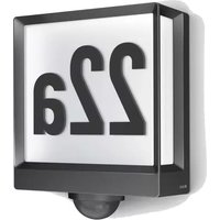
| Product type | 360° detection lamp |
| Brand | Steinel |
| Model | L400S |
| Category | Outdoor lighting |
| Mains voltage | 220-240 V / 50-60 Hz |
| Max bulb wattage | 60 W (no energy-saving lamps) |
| Own consumption | 1.3 W |
| Detection angle | 360° (opening angle 120°) |
| Detector range | Front 12 m, side 6 m |
| Adjustable delay | 10 sec - 15 min |
| Twilight setting | 2 lux - 2000 lux |
| Brightness adjustment (Watt-o-matic) | 0 to 50 % (standby 10-30 W) |
| Pivotable detector | 2 x 40° in all directions |
| Protection rating | IP 44 (splash proof) |
| Ambient temperature | -25°C to +55°C |
| Warranty | 36 months |
| Standards | CE, Low Voltage Directive 73/23/EEC, EMC 89/336/EEC |
| Lens maintenance | Damp cloth without cleaning agent |
| Installation safety | Disconnect power before any connection, comply with standard NF-C15100 |
Frequently Asked Questions - L400S STEINEL
User questions about L400S STEINEL
0 question about this device. Answer the ones you know or ask your own.
Ask a new question about this device
Download the instructions for your Lighting in PDF format for free! Find your manual L400S - STEINEL and take your electronic device back in hand. On this page are published all the documents necessary for the use of your device. L400S by STEINEL.
USER MANUAL L400S STEINEL
(IRD)STC SOCKET TOOL COMPANY Limited
- Queen Street, Smithfield - IRL-Dublin
Tel: +353/1/8725433 · Fax +353/1/8725195
sockettool@eircom.net
FOUVAUCHEI S.A.
ACTICENTRE - CTR 2
Bue des Farnardis - Bat. M - Lot 3 - E-59818 Lesquin Cecier
Tel: +39320303400 · Fax: +39320608420
www.duwauchel.com
NLVAN SPIJK AGENTUREN BY
Postbus 2 · NL-5688 ZH Cirschot
De Scheper 260 · NL-5698 HP Oirschet
Tel: +31/499/571810 · Fax +31/499/575795
www.vea-hegema.nl
(a) VSA handel Bvba
ATERSAN ITH. TIC. ve SAN. KOLL. STI
Add. Tersane Caddiesi Galata Hirdavatolar Carsisi No: 45
Karakoy/İstanbul-TURKE
Tel: +90212/2920664 Pbx · Fax +90212/2920665
www.alersan.com
© ELNAS sr.o.
Oblekovice 394 · CZ-67181 Znojmo
Tel: +420/515/220126 · Fax: +420/515/244347
www.einas.cz
(PL) LANGE ŁUKASZUK Sp.
Byków 25a · PL-55-095 Mirków
Tel: +48/71/3 98 08 861 · Fax: +48/71/3 98 19
natural_image
Close-up of a glowing incandescent light bulb mounted on a stand, with no visible text or symbols.StudioLine
D Bedienungsanleitung
GB Operating instructions
F Mode d'emploi
NL Gebruiksaanwijzing
① Istruzioni per l'uso
E Instrucciones de montaje
s Bruksanvisning
DK Brugsanvisning
FIN Käyttöohje
N Bruksanvisning
STEINEL®

Montageanleitung
natural_image
Simple weather icons showing sun, moon, and directional arrows (no text or symbols)GB Installation Instructions
Lights, alarms, and many other things triggered by movement – for your convenience and safety.
At the front door, garage, terrace or carport, in a stairway, storeroom or basement, this SensorLamp
can be installed and ready for operation quickly anywhere.
Principle of Operation
The built-in pyroelectric infrared detector detects the invisible heat radiation that is emitted by moving bodies (people, animals,
etc.). This thermal radiation is converted electronically, and switches on the light fixture. No thermal radiation is detected through bar-
riers such as walls or planes of glass. The fixture is not switched on.
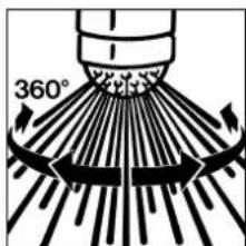
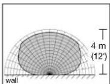
Focal points and angle of sight of the 360° STEINEL lens (with 120° angle of aperture).
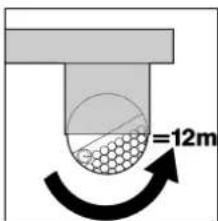
The most reliable motion detection is achieved by mounting or pointing the unit to aim across the direction in which a person would walk, and so that no hindrances such as trees or walls obstruct the line of sight.
Important: Teh max. reach is best achieved if the top row of lens segments is positioned directly under the housing.
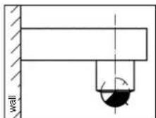
a) sensor lens directed forwards.
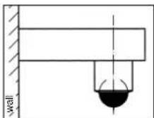
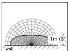
b) sensor lens directed downwards.

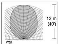
c) sensor lens directed backwards.
Monitoring zone A
Monitoring zone B
Monitoring zone C
Installation
Wall Mounting
Caution: The installation involves connecting the unit to the power mains. The line voltage can be lethal! So first switch off the power and check that the circuit is dead with a voltage tester.
Pull out the wall mount.
Do not undo the internal wiring of the lamp-wire connector, but extract the whole connector by pulling gently.
Hold the mounting plate against the wall and mark the drillholes (pay attention to where wiring runs in wall). Drill the holes and insert screw anchors.
In order to be able to perform switching operations, the connection to the power supply must be made by a power cord with at least two conductors. A hole can be punched in the rubber stopper with a screwdriver for this purpose. When the wires have been passed through, the mounting plate can be screwed on and aligned.
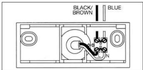
Connecting the power supply lead
The supply lead consists of a two-phase or three-phase wire:
L = phase conductor (usually black or brown) N = neutral conductor (usually blue)
PE = protective earth conductor, if present (green and yellow).

In case of doubt, identify the individual conductors by means of a voltage tester; then disconnect the power supply again.
The phase conductor (L) and the neutral conductor (N) go into their corresponding terminals, to which conductors of the same color are already connected. Protect the protective earth (PE) conductor with insulating tape.
Note: Mixing up the terminal connections can cause a short-circuit later in the unit or in your fuse box. In that case, the individual wires must be identified again and reconnected.
A power switch for switching the unit on and off can be installed in the supply lead, of course.
Function
Once the sensor light fixture has been wired up and
fastened to the wall support, it can be switched on.
Three settings can now be made on the light fixture's sensor lens.
natural_image
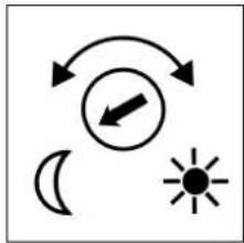
Simple weather icons showing sun, moon, and directional arrows (no text or symbols)a. Lighting controller (threshold)
The desired light threshold can be adjusted continuously from about 2 lux to 2,000 lux. The adjusting screw turned clockwise all the way equals daytime operation at approx. 2,000 lux; counter clockwise all the way equals nighttime operation at approx. 2 lux.
(The unit is shipped with a factory setting for daytime operation.) When adjusting the sensor light fixture detection zone and for a performance test during daylight, the adjusting screw must be turned clockwise all the way.

b. Switch-off delay (time setting)
The period for which the fixture should light up can be adjusted continuously, from about 10 seconds to 15 minutes. The adjusting screw turned clockwise all the way equals minimum time, approx. 10 seconds; counter clockwise all the
way equals maximum time, approx. 15 minutes. (The unit is shipped with a factory setting of the minimum time.) We recommend setting the unit to the minimum time when adjusting the SensorLamp's detection zone or carrying out a performance test.

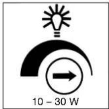
Infinitely variable brightness control (Watt-o-matic)
The following functions can be controlled by means of the dimmer control:
1) Adjusting screw turned clockwise all the way means that the sensor light fixture is switched off. Only when movement is detected is the light switched on at full power.
2) By setting the adjusting screw between center position and turned clockwise all the way, the brightness of the fixture in standby mode can be adjusted continuously between about
10 watts and a maximum of 30 watts. This means that when movement is detected the light switches from 20 W maintained lighting, for example, to maximum output (60 W).
3) Adjusting screw of dim- mer turned counter clockwise all the way and adjusting screw of lighting controller turned clockwise all the way: in this setting, the Sensor- Lamp is constantly on. If there is an on/off switch in the circuit, the sensor light fixture can be operated as a normal light fixture.
In order to switch on the light without a heat source in the detection zone, switch the indoor power switch momentarily. This will activate the light for the period selected.
Weather can affect the function of the sensor light fixture. Strong gusts of wind, snow, rain or hail may cause switching errors, because the unit cannot distinguish the sudden change of temperature.
The Fresnel lens should be periodically wiped clean with a damp cloth if it gets dirty. Do not use any cleaning materials.

Technical Specifications
Line voltage: 220 - 240 V/50 - 60 Hz
Power output: max. 60 watts (no low-energy bulbs)
Power consumption: 1.3 W
Detection angle of sensor: 360° all-round lens
(with 120° angle of aperture)
Swivelling range of sensor: 2 x 40° in every direction
ON time, adjustable: 10 sec. to 15 min.
Lighting threshold, adjustable: 2 - 2,000 lux
Brightness setting: 0 - 50% (Watt-o-matic)
Sensor range (dependent on sensor setting, ambient temperature, and direction of approach) From the front: 12 m (40') From the side: 6 m (20')
Type of enclosure: IP 44, splashproof
Ambient temperature: -25^ to +55^ (-13^ to +131^)
Troubleshooting
| Malfunction | Cause Remedy | |
| Sensor light fixture without power | ■ Fuse has blown; not switched on; break in wiring■ Short-circuit | ■ Replace fuse; switch on power switch; check wiring with voltage tester■ Check connections |
| Sensor light fixture does not switch on | ■ Lighting controller set to nighttime mode during daytime operation■ Bulb burned out■ Power switch off■ Fuse blown■ Detection zone not properly targeted■ Internal circuit-breaker has opened | ■ Adjust setting■ Replace light bulb■ Switch on■ Replace fuse, check connection if necessary■ Recalibrate■ Switch SensorLamp off and then on again |
| Sensor light fixture does not switch off | ■ Continuing movement in monitoring zone■ Set to continuous operation by indoor multi-circuit switch | ■ Check detection zone and recalibrate if necessary■ Switch multi-circuit switch to automatic |
| Sensor light fixture keeps switching on and off | ■ Animals moving in detection zone | ■ Tilt sensor higher; change detection zone |
| Sensor light fixture switches on when it should not | ■ Wind is moving trees or bushes in detection zone■ Cars in the street are being detected■ Sunlight is striking the lens■ Reflection from light-colored walls or pavements■ Sudden temperature changes due to weather (wind, rain, snow) or exhaust air from fans or open windows | ■ Change detection zone■ Change detection zone, tilt sensor down■ Install sensor in sheltered spot, or change detection zone■ Re-adjust lighting controller■ Change detection zone or install at different spot |
| Range of sensor light fixture changes | ■ Differing ambient temperatures | ■ When it is cold, shorten range by tilting sensor down■ When it is hot, tilt sensor up |
CE Declaration of conformity
This product is in conformity with standards of low voltage in accordance with
the regulations 73/23/EEC, 89/336/EEC.
This STEINEL product has been manufactured with great care, performance and safety tested according to current regulations, and then subjected to random sample testing. STEINEL guarantees that it is in perfect condition and operates correctly.
FUNCTIONAL 36 month WARRANTY
The warranty period is 36 months, beginning with the date of sale to the user. We will correct defects due to faulty material or manufacturing. The guarantee will be met by repair or replacement of defective parts, at our option.
Damage to wear parts, damage or defects occurring due to improper operation or maintenance or abuse are not covered.
Further consequential damage to other items is excluded.
Claims under the guarantee will only be granted if the product, not disassembled, with sales slip or invoice (date of purchase and dealer's stamp) is sent, well packed, to the appropriate Service Center, or handed in to the dealer within the first 6 months.
Repair-Service: Our customer service de- partment will repair faults not covered by the guaran- tee, or after the guarantee has expired. Please send the product, well packed, to the nearest Service Center.

L = Phase (souvent noir ou marron)
natural_image
Simple weather icons showing sun, moon, and directional arrows (no text or symbols)natural_image
Simple weather icons showing sun, moon, and directional arrows (no text or symbols)Traploze lichtsterkte-instelling (Watt-o-matic)
natural_image
Simple weather icons showing sun, moon, and directional arrows (no text or symbols)PE = Eventual conductor a tierra (verde/amarillo)
natural_image
Simple weather icons showing sun, moon, and directional arrows (no text or symbols)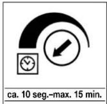
natural_image
Simple weather icons showing sun, moon, and directional arrows (no text or symbols)Steglös Ijusreglering (dimring)
natural_image
Simple weather icons showing sun, moon, and directional arrows (no text or symbols)Trinlos lysstyrkeregulering (Watt-o-matic)
natural_image
Simple weather icons showing sun, moon, and directional arrows (no text or symbols)natural_image
Simple weather icons showing sun, moon, and directional arrows (no text or symbols)a) Skumringsinnstilling
Den ønskede skumringsni-vået kan stilles inn trinnlöst fra ca. 2 Lux til 2000 Lux. Når skruen er dreiet helt mot høyre (2000 Lux) vil lampen reagere også i daglys. Når skruen er dreiet helt mot venstre, vil lampen först tenne när det