
EY46A2 - Grinder PANASONIC - Free user manual and instructions
Find the device manual for free EY46A2 PANASONIC in PDF.

| Product Type | Cordless Angle Grinder |
| Brand | Panasonic |
| Model | EY46A2 |
| Maximum Wheel Diameter | 125 mm |
| Spindle Thread | M14 |
| Weight (with battery) | 1.65 kg |
| Total Length | 300 mm |
| Motor Type | Brushless DC |
| Rated Voltage | 14.4 V or 18 V (depending on battery) |
| No Load Speed | 8000 rpm (14.4 V) / 10000 rpm (18 V) |
| Battery Type | Li-ion (models EY9L41, EY9L42, EY9L44, EY9L45, EY9L50, EY9L51) |
| Compatible Charger | EY0L82 |
| Main Uses | Grinding and cutting |
| Safety | Motor brake, overload protection, lock indicator, protective guard |
| Maintenance | Cleaning with a dry cloth, replacing carbon brushes (every 5 mm of wear) |
| Included Accessories | Grinding wheel guard, flange, clamping nut, wrench |
| Optional Accessories | Cutting disc, cutting disc guard |
| Repairability | Spare parts available (carbon brushes, flange, nut); repair by Panasonic authorized center |
Frequently Asked Questions - EY46A2 PANASONIC
User questions about EY46A2 PANASONIC
0 question about this device. Answer the ones you know or ask your own.
Ask a new question about this device
Download the instructions for your Grinder in PDF format for free! Find your manual EY46A2 - PANASONIC and take your electronic device back in hand. On this page are published all the documents necessary for the use of your device. EY46A2 by PANASONIC.
USER MANUAL EY46A2 PANASONIC
Operating Instructions
Bedienungsanleitung
Cordless Angle Grinder
Kabelloser Winkelschleifer
natural_image
3D rendering of a mechanical power tool with angular grip and handle (no text or symbols visible)| (A) | Power switchNetzschalterInterrupteur d'alimentationInterruttore di accensioneHoofdschakelaarInterruptor de alimentaciónAfbryderStrömbrytareStrömbryterKäyttökytkinAçma/Kapama düğmesi | (B) | Brush capBürstenkappeCapuchon des charbonsCapsula spazzoleBorstelkapTapa de cepilloBørstehætteBorstlockBørstehetteHarjan suojusFırça kapağı |
| (C) | Display panelAnzeigefeldEcran d'affi chageDisplayDisplaypaneelPanel de exhibiciónDisplaypanelDisplayDisplaypanelNäyttöpaneeliGösterge paneli | (D) | Battery low warning lampAkkuladungs-WarnlampeTémoin d'avertissement de batterie basseSpia avvertenza batteria scaricaWaarschuwingslampje voor lage accuspanningLuz de aviso de baja carga de bateríaAdvarselslampes batterieffekt lavVarningslampa för svagt batteriVarsellampe for at batteriet er for lavtAlhaisen akkujännitteen varoituslamppuPil zayıf uyarı lambası |
| (E) | On lock warning lampEinschaltsicherungsleuchteTémoin d'avertissement à verrou activéSpia avvertenza blocco utensileWaarschuwingslampje inschakelvergrendelingLuz de advertencia de bloqueoLåseadvarselslampeVarningslampa för påslagningssäkringVarsellampe for innkoblingssikringTurvalukituksen merkkivaloKilit uyarı lambası | (F) | Overheat warning lamp (battery)Überhitzungs-Warnlampe (Akku)Témoin d'avertissement de surchauffe (batterie)Spia avvertenza surriscaldamento (batteria)Oververhitting-waarschuwingslampje (accu)Luz de advertencia de sobrecalentamiento (batería)Advarselslamp til overophedning (batteri)Varningslampa för överhettning (batteri)Varsellampe for overoppheting (batteri)Ylikuumenemisen varoituslamppu (akku)Aşırı ısınma uyarı lambası (batarya) |
| (G) | Battery pack release buttonAkku-EntriegelungsknopfBouton de libération de batterie autonomeTasto di rilascio pacco batteriaAccu-ontgrendeltoetsBotón de liberación de bateríaUdløserknap til batteripakningFrigöringsknapp för batteriUtløserknapp for batteripakkeAkkupaketin irrotuspainikeBatarya paketi çıkarma düğmesi Akku- | (H) | Alignment markAusrichtmarkierungMarque d'alignementMarcatura di allineamentoUitlijntekensMarca de alineaciónFlugtemærkeAnpassningsmärkenInnrettingsmerkeSovitusmerkkiHizalama işareti |
| (I)(K) | Battery packAkkuBatterie autonomePacco batteriaAccuBateríaBatteripakningBatteriBatteripakkeAkkuBatarya paketiSupport handle mounting holeMontageloch für StützgriffOrifi ce de montage du manche de supportForo montaggio maniglia di sostegnoMontage-opening van handgreepOrifi cio de montaje de mango de soporteMonteringshul til hjælpehåndtagMonteringshål för stödhandtagMonteringshull for støttehåndtakTukikahvan asennusaukkoDestek kolu montaj deligi | (J)(L) | Support handleZusatzgriffManche de supportManiglia di sostegnoHandgreepMango de soporteHjælpehändtagStödhandtagStøttehändtakTukikahvaDestek koluGrinding disc guardSchleifscheibenschutzCarter de disque abrasifCarter disco molaAfbraamschijfbeschermkapProtección de disco de desbastadoSlibeskivebeskytterSlipskivans skyddSlipeskiveskjermHiomalaikan suojusTaşlama diski koruyucu |
| (M) | Grinding disc guard fi xing screwSchleifscheibenschutzschraubeVis de fi xation du carter de disque abrasifVite di fi ssaggio carter disco molaBevestigingsschroef van afbraamschijfbeschermkapTomillo de fi jación de protector de disco de amoladoraSlibeskivebeskytter skrueLåsskruv för slipskivans skyddFesteskrue for slipeskiveskjermHiontalaikan suojuksen kiinnitysruuviTaşlama diski koruyucu sabitleme vidası | (N) | SpindleSpindelAxeAsseAsEjeSpindelSpindelSpindelKaraİşmili |
| (O) | Spindle lock buttonSpindelverriegelungstasteBouton de blocage de l'axePulsante di blocco asseAfbraamschijfBotón de bloqueo de ejeSpindellåseknappSpindellåseknappKaran lukituspainikeİşmili kilitleme düğmesi | (P) | Battery chargerLadegerätChargeur de batterieCaricabatterieAcculaderCargador de bateríaBatteriopladerBatteriladdareBatteriladerAkkulaturiBatarya şarj cihazı |
| (Q) | Battery pack coverAkuabdeckungCouvercle de la batterie autonomeCoperchio batterieAccudekselCubierta de la bateríaAkkuafdækningBatterilockBatteripakkedekselAkun liitinsuojaBatarya paketi kapağı | (R) | Clamp nutMutterÉcrou de serrage de collierDado di fi ssaggioKlemmoerTuerca de abrazaderaMøtrikMutterKlemmutterAluslevySıkma somunu |
| (S) | Disc fl angeScheibenfl anschFlasque du disqueFlangia discoSchijffl ensBrida de discoSkivefl angeSkivfl änsSkivefl ensLaikan lukituslaippaDisk flanşı | (T) | Disc wrenchScheibenschlüsselClé de disqueChiave per il discoSchijfsleutelLlave de discoSkivenøgleSkivnyckelSkivenøkkelLukituslaipan avainDisk anahtarı |
Original instructions: English Translation of the original instructions: Other languages
I. INTENDED USE
Thank you for purchasing the Panasonic Angle Grinder. The powerful grinding action of this tool, combined with the convenience of its rechargeable battery pack, provides you with great grinding performance.
This Angle Grinder is only to be used for grinding and cutting-off.
DANGER
This product is a grinding tool, designed to grind. It has a rotating disc which is capable of cutting you deeply, causing serious injury or death. As a result, please read this manual and the cautionary markings on the tool carefully, and obey all of the Safety Instructions to avoid such injury.
WARNING
To reduce the risk of injury, always use proper guards when grinding.
How to Use This Manual
- Please read this manual completely before starting to use your grinder. If you let someone else use the grinder, make sure they either read this manual or are fully instructed in the proper use and all safety precautions concerning the grinder.
- Please keep this manual for future reference. It contains important safety information that you must follow to use the grinder safely.
- This manual and product use the following signal words:
NOTE:
Notes provide additional information that you should know about the grinder.
CAUTION
Caution indicates a potentially hazardous situation, which could result in minor or moderate injury if not avoided. Cautions also alert you to unsafe practices to be avoided.
WARNING
Warning indicates a potentially hazardous situation, which could result in serious injury or death if not avoided.
DANGER
Danger indicates an imminent hazard which will result in serious injury or death if not avoided.
Read the "Safety Instructions" booklet and the following before using.
II. ADDITIONAL SAFETY RULES
Safety instructions for all operations
Safety warning common for Grinding or Abrasive Cutting-off operations:
1) This power tool is intended to function as a grinder, or cut-off tool. Read all safety warnings, instructions, illustrations and specifications provided with this power tool. Failure to follow all instructions listed below may result in electric shock, fire and/or serious injury.
2) Operations such as sanding, wire brushing, polishing are not recommended to be performed with this power tool. Operations for which the power tool was not designed may create a hazard and cause personal injury.
3) Do not use accessories which are not specifically designed and recommended by the tool manufacturer. Just because the accessory can be attached to your power tool, it does not assure safe operation.
4) The rated speed of the accessory must be at least equal to the maximum speed marked on the power tool. Accessories running faster than their RATED SPEED can break and fly apart.
5) The outside diameter and the thickness of your accessory must be within the capacity rating of your power tool. Incorrectly sized accessories cannot be adequately guarded or controlled.
6) Threaded mounting of accessories must match the grinder spindle thread. For accessories mounted by flanges, the arbour hole of the accessory must fit the locating diameter of the flange. Accessories
that do not match the mounting hardware of the power tool will run out of balance, vibrate excessively and may cause loss of control.
7) Do not use a damaged accessory. Before each use inspect the accessory such as abrasive wheels for chips and cracks. If power tool or accessory is dropped, inspect for damage or install an undamaged accessory. After inspecting and installing an accessory, position yourself and bystanders away from the plane of the rotating accessory and run the power tool at maximum no-load speed for one minute. Damaged accessories will normally break apart during this test time.
8) Wear personal protective equipment. Depending on application, use face shield, safety goggles or safety glasses. As appropriate, wear dust mask, hearing protectors, gloves and workshop apron capable of stopping small abrasive or workpiece fragments. The eye protection must be capable of stopping flying debris generated by various operations. The dust mask or respirator must be capable of filtrating particles generated by your operation. Prolonged exposure to high intensity noise may cause hearing loss.
9) Keep bystanders a safe distance away from work area. Anyone entering the work area must wear personal protective equipment. Fragments of workpiece or of a broken accessory may fly away and cause injury beyond immediate area of operation.
10) Hold the power tool by insulated gripping surfaces only, when performing an operation where the cutting tool may contact hidden wiring. Contact with a "live" wire will also make exposed metal parts of the power tool "live" and could give the operator an electric shock.
11) Position the cord clear of the spinning accessory. If you lose control, the cord may be cut or snagged and your hand or arm may be pulled into the spinning accessory.
12) Never lay the power tool down until the accessory has come to a complete stop. The spinning accessory may grab the surface and pull the power tool out of your control.
13) Do not run the power tool while carrying it at your side. Accidental contact with the spinning accessory could snag your clothing, pulling the accessory into your body.
14) Regularly clean the power tool's air vents. The motor's fan will draw the dust inside the housing and excessive accumulation of powdered metal may cause electrical hazards.
15) Do not operate the power tool near flammable materials. Sparks could ignite these materials.
16) Do not use accessories that require liquid coolants. Using water or other liquid coolants may result in electrocution or shock.
Further safety instructions for all operations
Kickback and Related Warnings
Kickback is a sudden reaction to a pinched or snagged rotating wheel, backing pad, brush or any other accessory. Pinching or snagging causes rapid stalling of the rotating accessory which in turn causes the uncontrolled power tool to be forced in the direction opposite of the accessory's rotation at the point of the binding.
For example, if an abrasive wheel is snagged or pinched by the workpiece, the edge of the wheel that is entering into the pinch point can dig into the surface of the material causing the wheel to climb out or kick out. The wheel may either jump toward or away from the operator, depending on direction of the wheel's movement at the point of pinching. Abrasive wheels may also break under these conditions. Kickback is the result of power tool misuse and/or incorrect operating procedures or conditions and can be avoided by taking proper precautions as given below.
1) Maintain a firm grip on the power tool and position your body and arm to allow you to resist kickback forces. Always use auxiliary handle, if provided, for maximum control over kickback or torque reaction during start-up. The operator can control torque reactions or kickback forces, if proper precautions are taken.
2) Never place your hand near the rotating accessory. Accessory may kickback over your hand.
3) Do not position your body in the area where power tool will move if kickback occurs. Kickback will propel the tool in direction opposite to the wheel's movement at the point of snagging.
4) Use special care when working corners, sharp edges etc. Avoid bouncing and snagging the accessory. Corners, sharp edges or
bouncing have a tendency to snag the rotating accessory and cause loss of control or kickback.
5) Do not attach a saw chain woodcarving blade or toothed saw blade. Such blades create frequent kickback and loss of control.
Additional safety instructions for grinding and cutting-off operations
Safety warnings specific for Grinding and Abrasive Cutting-off operations:
1) Use only wheel types that are recommended for your power tool and the specific guard designed for the selected wheel. Wheels for which the power tool was not designed cannot be adequately guarded and are unsafe.
2) The grinding surface of centre depressed wheels must be mounted below the plane of the guard lip. An improperly mounted wheel that projects through the plane of the guard lip cannot be adequately protected.
3) The guard must be securely attached to the power tool and positioned for maximum safety, so the least amount of wheel is exposed towards the operator. The guard helps to protect operator from broken wheel fragments and accidental contact with wheel and sparks that could ignite clothing.
4) Wheels must be used only for recommended applications. For example: do not grind with the side of cut-off wheel. Abrasive cut-off wheels are intended for peripheral grinding, side forces applied to these wheels may cause them to shatter.
5) Always use undamaged wheel flanges that are of correct size and shape for your selected wheel. Proper wheel flanges support the wheel thus reducing the possibility of wheel breakage. Flanges for cut-off
wheels may be different from grinding wheel flanges.
6) Do not use worn down wheels from larger power tools. Wheel intended for larger power tool is not suitable for the higher speed of a smaller tool and may burst.
Additional Safety Warnings Specific for Abrasive Cutting- Off Operations:
1) Do not "jam" the cut-off wheel or apply excessive pressure. Do not attempt to make an excessive depth of cut. Overstressing the wheel increases the loading and susceptibility to twisting or binding of the wheel in the cut and the possibility of kickback or wheel breakage.
2) Do not position your body in line with and behind the rotating wheel. When the wheel, at the point of operation, is moving away from your body, the possible kickback may propel the spinning wheel and the power tool directly at you.
3) When wheel is binding or when interrupting a cut for any reason, switch off the power tool and hold the power tool motionless until the wheel comes to a complete stop. Never attempt to remove the cut-off wheel from the cut while the wheel is in motion otherwise kickback may occur. Investigate and take corrective action to eliminate the cause of wheel binding.
4) Do not restart the cutting operation in the workpiece. Let the wheel reach full speed and carefully reenter the cut. The wheel may bind, walk up or kickback if the power tool is restarted in the workpiece.
5) Support panels or any oversized workpiece to minimize the risk of wheel pinching and kickback. Large workpieces tend to sag under their own weight. Supports must be placed under the workpiece near
the line of cut and near the edge of the workpiece on both sides of the wheel.
6) Use extra caution when making a "pocket cut" into existing walls or other blind areas. The protruding wheel may cut gas or water pipes, electrical wiring or objects that can cause kickback.
| Symbol | Meaning |
| V Volts | |
| --- | Direct current |
| n Rated speed | |
| ... min ^-1 | Revolutions or reciprocations per minutes |
| Ah | Electrical capacity of battery pack |
 | To reduce the risk of injury, user must read and understand instruction manual. |
| [E247] | For indoor use only. |
 | Always wear eye protection |
Otherwise, the battery may overheat, catch fire, or explode.
- Never use other than the dedicated charger to charge the battery pack. Otherwise, the battery may leak, overheat, or explode.
• After removing the battery pack from the tool or the charger, always reattach the pack cover. Otherwise, the battery contacts could be shorted, leading to a risk of fire. - When the Battery Pack Has Deteriorated, Replace It with a New One. Continued use of a damaged battery pack may result in heat generation, ignition or battery rupture.
III. ASSEMBLY
NOTE:
When attaching or removing a support handle, disconnect battery pack from tool.
natural_image
Technical illustration of a mechanical power tool with two blades and central hub (no text or symbols)WARNING
- Do not use other than the Panasonic battery packs that are designed for use with this rechargeable tool.
- Panasonic is not responsible for any damage or accident caused by the use of the recycled battery pack and the counterfeit battery pack.
- Do not dispose of the battery pack in a fire, or expose it to excessive heat.
- Do not drive the likes of nails into the battery pack, subject it to shocks, dismantle it, or attempt to modify it.
- Do not allow metal objects to touch the battery pack terminals.
- Do not carry or store the battery pack in the same container as nails or similar metal objects.
- Do not charge the battery pack in a high-temperature location, such as next to a fire or in direct sunlight.
CAUTION
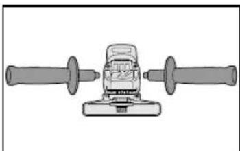
Always be sure that the support handle is installed securely before operation.
- Screw the side handle securely as shown in the figure.
CAUTION:
Never actuate the lock pin when the spindle is rotating. The tool may be damaged.
- Press the lock button to prevent spindle rotation when installing or removing parts, such as grinding disc, disc guard, etc.
Installing or removing disc Inspection before use
- Has the correct grinding disc been mounted for the object to be ground?
- Has the proper diameter of the grinding disc been mounted for the tool rating?
- Has the correct disc been fitted in compliance safety standards listed below?
Europe - EN, Australia - AS
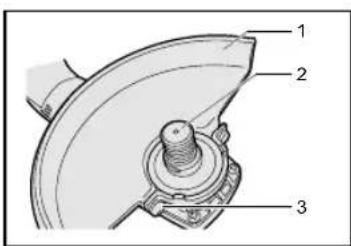
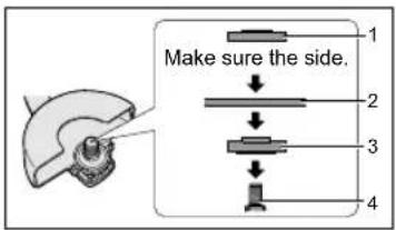
- Grinding disc guard
- Spindle
- Grinding disc guard fixing screw
CAUTION
- When using, the Grinding disc guard must be installed on the tool so that the closed side of the guard always faces toward the operator.
- Ensure that blotters are used when they are provided with the bonded abrasive product and when they are required;
WARNING:
Always use supplied guard when using tool. Grinding disc can shatter during use and Grinding disc guard helps to reduce chances of personal injury.
- Install the Grinding disc guard, and then securely tighten the screw.
flowchart
graph TD
    A["Raw Material Input"] --> B{Side Setup}
    B -->|Make sure the side.| C["Step 1: Side preparation"]
    B -->|Make sure the side.| D["Step 2: Side preparation"]
    B -->|Make sure the side.| E["Step 3: Side preparation"]
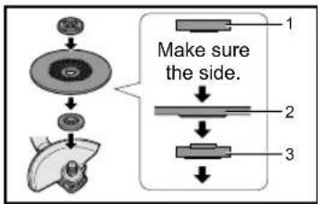
- Clamp nut
- Grinding disc
-
Disc flange
-
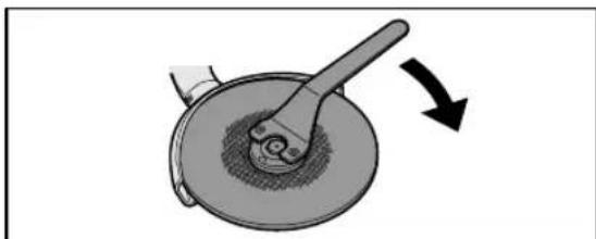
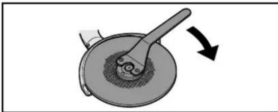
Install the disc flange and the disc to the spindle in order as shown in the figure.
- Tighten the clamp nut onto the spindle so that hollow side faces opposite direction to the disc.
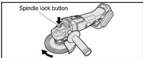
- Push the Spindle lock button to secure the spindle in place, and then use the clamp nut wrench to tighten the clamp nut securely.
natural_image
Diagram of a mechanical device with a lever and rotating wheel (no text or symbols)- To remove the grinding disc, follow the installation procedure in reverse.
Attaching or Removing Battery Pack
CAUTION
Before inserting battery pack, check that the power switch on the tool actuates properly and returns to the "OFF" position when released.
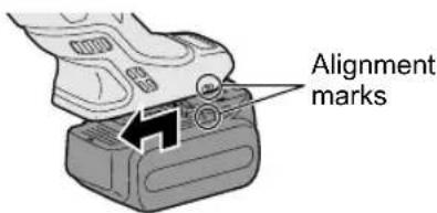
- To connect the battery pack:
Align the highlighted marker points and attach battery pack.
- Slide the battery pack until it locks into position.
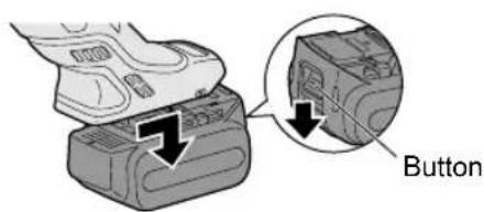
- To remove the battery pack:
Push down the button and slide the battery pack forward.
IV. OPERATION
NOTE:
Be aware that this tool is always in an operating condition, since it does not have to be plugged into an electrical outlet.
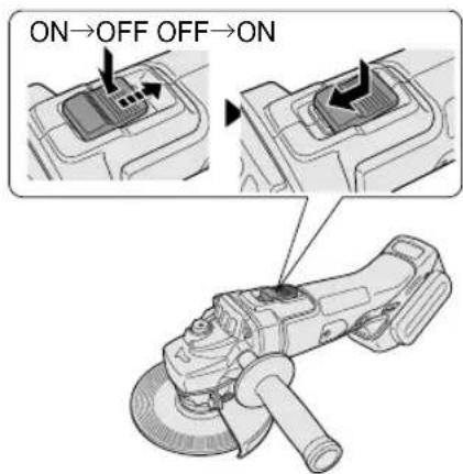
Power switch operation
CAUTION
- Before inserting the battery pack into the tool, always make sure that the power switch operates properly and returns to the "OFF" position when the rear of the power switch is depressed.
- Power switch can be locked in "ON" position. Stay alert when locking tool in "ON" position and grasp the tool firmly using support handle and grip.
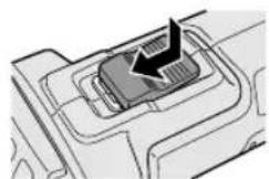
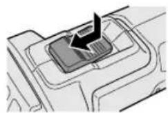
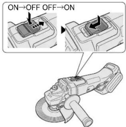
To start operation, press and slide the power switch toward the "ON" position.
natural_image
Diagram of a mechanical component with internal channels and a black arrow indicating direction (no text or symbols)For continuous operation, press the front of the power switch to lock it.
natural_image
Diagram of a mechanical component with a black arrow indicating direction (no text or symbols)
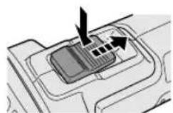
natural_image
Technical diagram of a mechanical component with a central slot and internal channels (no text or symbols)To stop the tool, press the rear of the power switch, then it returns to the "OFF" position.
WARNING
- It should never be necessary to force the tool. The weight of the tool applies adequate pressure. Forcing and excessive pressure could cause dangerous grinding disc breakage.
- ALWAYS replace grinding disc if tool is dropped while grinding.
• NEVER bang or hit grinding disc. - Avoid bouncing and snagging the grinding disc, especially when working corners, sharp edges etc. This can cause loss of control and kickback.
CAUTION
After operation, always switch off the tool and wait until the wheel has come to a complete stop before putting the tool down.
Visual inspection and workout test on disc
- Always make sure that the disc has no cracks before use.
- Always give workout test on the blade as follows.
- Always make sure the disc is firmly fixed.
| Work out time | |
| Brand new disc more than 3 min. | |
| Before use on current disc | more than 1 min. |
Grinding operation
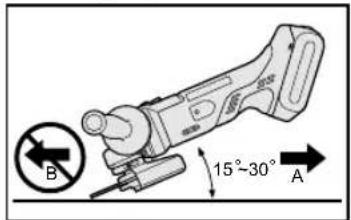
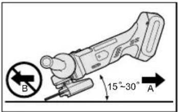
ALWAYS hold the tool firmly with one hand on grip and the other on the support handle. Turn on the tool and then apply the wheel or disc to the workpiece. In general, keep the edge of the wheel or grinding disc at an angle of about 15^-30^ to the workpiece surface. When using a new grinding disc, do not work the grinder in the B direction or it will cut into the workpiece. Once the edge of the grinding disc has been rounded off by use, the grinding disc may be worked in both A and B direction.
Using a cut-off disc guard (Available as an accessory, not included)
- Clamp nut
- Cut-off disc
- Disc flange
- Spindle
WARNING
- When using an abrasive cut-off disc, be sure to use only the cut-off disc guard designed for this use with cut-off disc.
- NEVER use cut-off disc for grinding.
- Do not jam the Disc or apply excessive pressure. Do not attempt to make an excessive depth of cut. Overstressing the cut-off disc increases the loading and susceptibility to twisting or binding of the cut-off disc in the cut and the possibility of kickback, cut-off disc breakage and overheating of the motor may occur.
- Do not start when disc is in the workpiece. To do so causes the cut-off disc binding or kickback. Let the cut-off disc reach full speed and then carefully cut the workpiece.
- During cutting operations, never change the angle of the disc. Placing side pressure on the cut-off disc (as in grinding) will cause the disc to crack and break, causing serious personal injury.
CAUTION
• To prevent excessive temperature increase of the tool surface, do not operate the tool continuously using two or more battery packs. The tool needs cool-off time before switching to another pack.
- Do not close up ventilation slots on the sides of the body during operation. Otherwise, the machine function is adversely affected to cause a failure.
- Do not strain the tool (motor). This may cause damage to the unit.
- Use the tool in such a way as to prevent the air from the ventilation slots from blowing directly onto your skin. Otherwise, you may get burned.
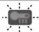
Indicator lamp for On lock start prevention function
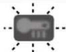
The grinder will not start when the battery pack is inserted with the switch at the ON position (switch lever at ON). The warning lamp will flash at this time to indicate that the 'On lock start prevention function' has operated.
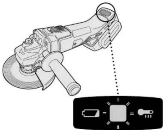
natural_image
Illustration of a power tool with a magnified view showing its internal components (no text or symbols present)Press the switch to the OFF position (switch lever at OFF) and then press it back to the ON position (switch lever at ON) to start the grinder.
Overheat warning lamp

Off (normal operation)

Flashing: Overheat Indicates operation has been halted due to battery overheating.
To protect the battery, be sure to note the following when carrying out this operation.
- If the battery becomes hot, the protection function will be activated and the motor or battery will stop operating. The overheat warning lamp on the control panel illuminates or flashes when this feature is active.
- If the overheating protection feature activates, allow the tool to cool thoroughly (at least 30 minutes). The tool is ready for use when the overheat warning lamp goes out.
- Avoid using the tool in a way that causes the overheating protection feature to activate repeatedly.
- If the tool is operated continuously under high-load conditions or if it is used in hot-temperature conditions (such as during summer), the overheating protection feature may activate frequently.
- If the tool is used in cold-temperature conditions (such as during winter) or if it is frequently stopped during use, the overheating protection feature may not activate.
- The performance of the EY9L42 deteriorates significantly at and below 10°C due to work conditions and other factors.
- The ambient temperature range is between 0°C (32°F) and 40°C (104°F). If the battery pack is used when the battery temperature is below 0°C (32°F), the tool may fail to function properly.
- When charging a cool battery pack (below 0°C (32°F)) in a warm place, leave the battery pack at the place and wait for more than one hour to warm up the battery to the level of the ambient temperature.
Battery low warning lamp

Off (normal operation)

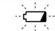
Flashing (No charge) Battery protection feature active
Excessive (complete) discharging of lithium ion batteries shortens their service life dramatically. The tool includes a battery protection feature designed to prevent excessive discharging of the battery pack.
- The battery protection feature activates immediately before the battery loses its charge, causing the battery low warning lamp to flash.
- If you notice the battery low warning lamp flashing, charge the battery pack immediately.
- If it is started with too little battery power remaining, the tool may stop operating without the battery low warning lamp flashing first. This indicates that there is too little battery power remaining to use the tool, and the battery pack should be charged before further use.
- If the tool is subject to a sudden load during use that causes the motor to lock up, the overdischarge prevention sensor may be triggered, and the battery low warning lamp may flash. The lamp will stop flashing once you address the cause of the motor's locking up and cycle the trigger.
[Battery Pack]
For Appropriate Use of Battery pack
Li-ion Battery pack
- For optimum battery life, store the Li-ion battery pack following use without charging it.
- When charging the battery pack, confirm that the terminals on the battery charger are free of foreign substances such as dust and water etc. Clean the terminals before charging the battery pack if any foreign substances are found on the terminals.
The life of the battery pack terminals may be affected by foreign substances such as dust and water etc. during operation.
- When battery pack is not in use, keep it away from other metal objects like: paper clips, coins, keys, nails, screws, or other small metal objects that can make a connection from one terminal to another.
Shorting the battery terminals together may cause sparks, burns or a fire. - When operating the battery pack, make sure the work place is well ventilated.
- When the battery pack is removed from the main body of the tool, replace the battery pack cover immediately in order to prevent dust or dirt from contaminating the battery terminals and causing a short circuit.
Battery Pack Life
The rechargeable batteries have a limited life. If the operation time becomes extremely short after recharging, replace the battery pack with a new one.
Battery Recycling
ATTENTION:
For environmental protection and recycling of materials, be sure that it is disposed of at an officially assigned location, if there is one in your country.
Recommendations for use
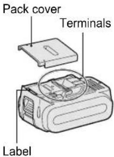
Be sure to use the Pack cover
- When the battery pack is not being used, store the battery in a way that foreign substances such as dust and water etc. do not contaminate the terminals. Be sure to attach the battery pack cover to protect the battery terminals.
- When charging the battery pack, confirm that the terminals on the battery charger are free of foreign substances such as dust and water etc. Clean the terminals before charging the battery pack if any foreign substances are found on the terminals. The life of the battery pack terminals may be affected by foreign substances such as dust and water etc. during operation.
CAUTION
To protect the motor or battery, be sure to note the following when carrying out operation.
- If the battery becomes hot, the protection function will be activated and the battery will stop operating. The overheat warning lamp on the control panel illuminates or flashes when this feature is active.
For safe use
- The battery pack is designed to be installed by proceeding two steps for safety. Make sure the battery pack is installed properly to the main unit before use.
- If the battery pack is not connected firmly when the switch is switched on, the
overheat warning lamp and the battery low warning lamp will flash to indicate that safe operation is not possible, and the main unit will not rotate normally. Connect the battery pack into the unit of the tool until the red or yellow label disappears.
[Battery Charger] Charging
CAUTION
- The charger is designed to operate on standard domestic electrical power only as stated in the rating plate. Charge only on the voltage indicated on the rating plate of unit. e.g.230V / 50Hz.
- Do not attempt to use it on any other voltage or frequency rating.
- The ambient temperature range is between 0°C (32°F) and 40°C (104°F).
- If the battery pack is used when the battery temperature is below 0°C (32°F), the tool may fail to function properly.
- If the temperature of the battery pack falls approximately below 0°C (32°F), charging will automatically stop to prevent degradation of the battery.
- Use the charger at temperatures between 0°C and 40°C, and charge the battery at a temperature similar to that of the battery itself. (There should be no more than a 15°C difference between the temperatures of the battery and the charging location.)
- When charging a cool battery pack (below 0°C (32°F) in a warm place, leave the battery pack at the place and wait for more than one hour to warm up the battery to the level of the ambient temperature.
- Cool down the charger when charging more than two battery packs consecutively.
- Do not insert your fingers into contact hole, when holding charger or any other occasions.
• To prevent the risk of fire or damage to the battery charger.
-
Do not use power source from an engine generator.
-
Unplug the charger when not in use.
NOTE:
Your battery pack is not fully charged at the time of purchase. Be sure to charge the battery before use.
How to charge
- Plug the charger into the AC outlet.
NOTE:
Sparks may be produced when the plug is inserted into the AC power supply, but this is not a problem in terms of safety.
-
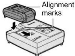
Connect the battery pack firmly into the charger.
-
Line up the alignment marks and place the battery onto the dock on the charger.
-
Slide forward in the direction of the arrow.
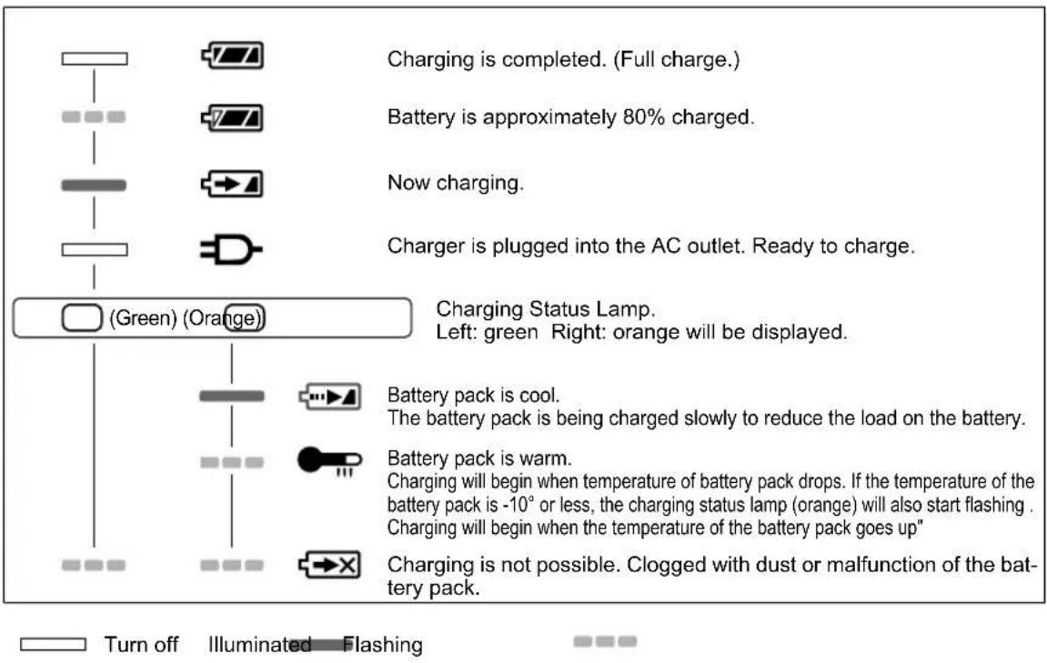
- During charging, the charging lamp will be illuminated. When charging is completed, an internal electronic switch will automatically be triggered to prevent overcharging.
- Charging will not start if the battery pack is warm (for example, immediately after heavy-duty operation). The orange standby lamp will be flashing until the battery cools down. Charging will then begin automatically.
-
The charge lamp (green) will flash slowly once the battery is approximately 80% charged.
-
When charging is completed, the charging lamp in green color will turn off.
-
If the temperature of the battery pack is 0^ C or less, charging takes longer to fully charge the battery pack than the standard charging time. Even when the battery is fully charged, it will have approximately 50% of the power of a fully charged battery at normal operating temperature.
-
Consult an authorized dealer if the charging lamp (green) does not turn off.
-
If a fully charged battery pack is inserted into the charger again, the charging lamp lights up. After several minutes, the charging lamp in green color will turn off.
LAMP INDICATIONS
Information for Users on Collection and Disposal of Old Equipment and used Batteries
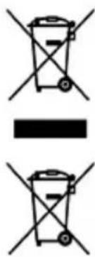
These symbols on the products, packaging, and/or accompanying documents mean that used electrical and electronic products and batteries should not be mixed with general household waste.
For proper treatment, recovery and recycling of old products and used batteries, please take them to applicable collection points, in accordance with your national legislation and the Directives 2002/96/EC and 2006/66/EC.
By disposing of these products and batteries correctly, you will help to save valuable resources and prevent any potential negative effects on human health and the environment which could otherwise arise from inappropriate waste handling.
For more information about collection and recycling of old products and batteries, please contact your local municipality, your waste disposal service or the point of sale where you purchased the items.
Penalties may be applicable for incorrect disposal of this waste, in accordance with national legislation.
For business users in the European Union
If you wish to discard electrical and electronic equipment, please contact your dealer or supplier for further information.
[Information on Disposal in other Countries outside the European Union]
These symbols are only valid in the European Union. If you wish to discard these items, please contact your local authorities or dealer and ask for the correct method of disposal.
Replacing carbon brushes
Keep the carbon brushes clean and free to slip in the holders. When it is less than 5 mm shorter both carbon brushes should be replaced at the same time. Use only identical carbon brushes.
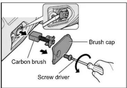
Use a screwdriver to remove the caps. Take out the worn carbon brushes, insert the new ones and secure the brush caps.
To maintain product SAFETY and RELIABILITY, repairs, any other maintenance or adjustment should be performed by Panasonic Authorized or Factory Service Centers, always using Panasonic replacement parts.
V. MAINTENANCE
- Use only a dry, soft cloth for wiping the unit. Do not use a damp cloth, thinner, benzine, or other volatile solvents for cleaning.
- In the event that the inside of the tool or battery pack is exposed to water, drain and allow to dry as soon as possible. Carefully remove any dust or iron filings that collect inside the tool. If you experience any problems operating the tool, consult with a repair shop.
VI. ACCESSORIES
CAUTION
• The use of any accessories not specified in this manual may result in fire, electric shock, or personal injury. Use recommended accessories only.
- Your tool is supplied with a guard for use with a grinding disc. A cut-off disc can also be used with a cut-off disc guard.
Grinding Disc
- Rated speed: greater than or equal to 72m/min
• Max. wheel diameter: Φ 125mm
• Hole diameter: Φ 22mm
• Max. thickness: 6mm
Grinding Disc Guard
- WEY46A2K3747
Cut-off Disc
- Rated speed: greater than or equal to 72m/min
• Max. wheel diameter: Φ125mm
• Hole diameter: Φ 22mm - Flat disc only
Cut-off Disc Guard (For cut-off disc)
- WEY46A2K3137
Disc Flange
• EY4640K1168
Clamp Nut
- WEY4640K1178
VII. SPECIFICATIONS
MAIN UNIT
| Mounting wheel diameter Φ125 mm | ||
| Spindle thread size M14 | ||
| Mounting wheel hole diameter 22 mm | ||
| Weight 1.65 kg (main unit only) | ||
| Overall length 300 mm (main unit only) | ||
| Noise, Vibration See the included sheet | ||
| Motor voltage DC 14.4 V DC 18 V | ||
| Rated speed 8000min | -1(rpm) 10000min | -1(rpm) |
BATTERY PACK
| Model No. | EY9L41 EY9L42 EY9L44 EY9L45 EY9L50 EY9L51 | ||||
| Storage battery Li-ion Battery | |||||
| Battery voltage DC 14.4 V DC 18 V | |||||
BATTERY CHARGER
| Model No. | EY0L82 | ||||||
| Electrical rating | See the rating plate on the bottom of charger | ||||||
| Weight | 0.93 kg | ||||||
| Charging time | Model No. | EY9L41 | EY9L42 | EY9L44 | EY9L45 | EY9L50 | EY9L51 |
| Usable | 35 min. | 30 min. | 40 min. | 50 min. | 40 min. | 55 min. | |
| Full | 50 min. | 35 min. | 55 min. | 60 min. | 55 min. | 70 min. | |
NOTE: This chart may include models that are not available in your area.
Please refer to the latest general catalogue.
For the dealer name and address, please see the included warranty card.
VIII. APPENDIX
WARRANTY SUPPLEMENT
- The breakdown and damage caused by usage consistent for a long time (e.g.: factory work on the assembly line, etc.) is out of warranty.
- Damage or failure caused by use of accessories that are not specified in this manual will not be covered by warranty.
ONLY FOR U.K.
IX. ELECTRICAL PLUG INFOR- MATION
FOR YOUR SAFETY PLEASE READ THE FOLLOWING TEXT CAREFULLY
This appliance is supplied with a moulded three pin mains plug for your safety and convenience.
A 5 amp fuse is fitted in this plug.
Should the fuse need to be replaced please ensure that the replacement fuse has a rating of 5 amp and that it is approved by ASTA or BSI to BS1362.
Check for the ASTA mark 🙏 or the BSI mark 🏠 on the body of the fuse.
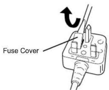
If the plug contains a removable fuse cover you must ensure that it is refitted when the fuse is replaced.
If you lose the fuse cover the plug must not be used until a replacement cover is obtained.
A replacement fuse cover can be purchased from your local Panasonic Dealer.
IF THE FITTED MOULDED PLUG IS UNSUITABLE FOR THE SOCKET OUTLET IN YOUR HOME THEN THE FUSE SHOULD BE REMOVED AND THE PLUG CUT OFF AND DISPOSED OF SAFELY.
THERE IS A DANGER OF SEVERE ELEC-TRICAL SHOCK IF THE CUT OFF PLUG IS INSERTED INTO ANY 13 AMP SOCKET.
If a new plug is to be fitted please observe the wiring code as shown below.
If in any doubt please consult a qualified electrician.
IMPORTANT:
The wires in this mains lead are coloured in accordance with the following code:
Blue: Neutral
Brown: Live
As the colours of the wire in the mains lead of this appliance may not correspond with the coloured markings identifying the terminals in your plug, proceed as follows.
The wire which is coloured BLUE must be connected to the terminal in the plug which is marked with the letter N or coloured BLACK.
The wire which is coloured BROWN must be connected to the terminal in the plug which is marked with the letter L or coloured RED.
Under no circumstances should either of these wires be connected to the earth terminal of the three pin plug, marked with
the letter E or the Earth Symbol ♦.
How to replace the fuse: Open the fuse compartment with a screwdriver and replace the fuse and fuse cover if it is removable.
This apparatus was produced to BS800.
natural_image
Diagram of a mechanical tool with two blades and a central hub (no text or symbols)⚠ VORSICHT
natural_image
Diagram of a mechanical device with a lever and rotating component, showing motion direction (no text or symbols)natural_image
Diagram of a mechanical component with a black arrow indicating direction (no text or symbols present)natural_image
Diagram of a mechanical component with an arrow indicating a specific feature (no text or symbols present)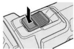
natural_image
Diagram of a mechanical component with a central rectangular block and directional arrow (no text or symbols)natural_image
Illustration of a power tool with a magnified view showing its internal components (no text or symbols present)natural_image
Diagram of a mechanical power tool with two blades and central hub (no text or symbols)MISE EN GARDE
natural_image
Diagram of a mechanical device with a lever and rotating wheel (no text or symbols)Operation de meulage
natural_image
Technical illustration of a power tool with a close-up of its internal components (no text or symbols)natural_image
Diagram of a mechanical power tool with two blades and central hub (no text or symbols)ATTENZIONE
natural_image
Diagram of a mechanical device with a lever and rotating component, showing motion direction (no text or symbols)natural_image
Diagram of a mechanical component with arrows indicating direction (no text or symbols)natural_image
Diagram of a mechanical component with an arrow indicating a specific feature (no text or symbols present)
natural_image
Technical diagram of a mechanical component with a central slot and directional arrow (no text or symbols)natural_image
Illustration of a power tool with a close-up of its internal components (no text or symbols)natural_image
Mechanical component diagram showing a central rotating tool with two flanged ends (no text or symbols)OPGELET
natural_image
Illustration of a mechanical tool interacting with a circular component, showing a curved arrow indicating rotation (no text or symbols present)natural_image
Diagram of a mechanical component with an arrow indicating a specific feature (no text or symbols present)
natural_image
Diagram of a mechanical component with a central rectangular block and directional arrow (no text or symbols)natural_image
Illustration of a power tool with a magnified view showing its internal components (no text or symbols present)natural_image
Diagram of a mechanical power tool with two blades and central hub (no text or symbols)PRECAUCIÓN
natural_image
Diagram of a mechanical component with a lever and rotating base, showing a curved arrow indicating rotation (no text or symbols present)natural_image
Technical diagram of a mechanical component with a highlighted section (no text or symbols)natural_image
Diagram of a power tool with a magnified view showing its internal components (no text or symbols present)natural_image
Diagram of a mechanical tool with two handles and a central component (no text or symbols)⚠ FORSIGTIG
- Slibeskivebe-skytter
- Spindel
- Slibeskivebe- skytter skrue
⚠ FORSIGTIG
natural_image
Diagram of a mechanical device with a lever and rotating wheel (no text or symbols)natural_image
Diagram of a mechanical component with a black arrow indicating a feature or process (no text or symbols present)natural_image
Two technical diagrams showing a mechanical component with arrows indicating direction, no text or symbols present.natural_image
Line drawing of a power tool with a magnified inset showing its internal components (no text or symbols)Tryk afbryderen til stilling OFF (afbryderarm i stilling OFF) og tryk den derefter tilbage til stilling ON (afbryderarm i stilling ON) for at starte slibemaskinen.
Advarselslampe for overophedning

Fra (normal anvendelse)


natural_image
Diagram of a mechanical power tool with two blades and central hub (no text or symbols)VIKTIGT
natural_image
Diagram of a mechanical device with a lever and rotating wheel (no text or symbols)natural_image
Two technical diagrams showing a mechanical component with arrows indicating direction (no text or symbols present)natural_image
Illustration of a power tool with a magnified view showing its internal components (no text or symbols present)natural_image
Technical line drawing of a mechanical tool with two flanges and a central hub (no text or symbols)⚠ FORSIKTIG
- Slipeskive-skjerm
- Spindel
- Festeskrue for slipeskiveskjerm
⚠ FORSIKTIG
natural_image
Diagram of a mechanical device with a lever and rotating component, showing motion direction (no text or symbols)natural_image
Illustration of a power tool with a close-up of its internal components (no text or symbols)Varsellampe for overoppheting

Av (normalt arbeid)

Slike symboler på produkter, emballasje, og/eller på medfølgende dokumenter betyr at brukte elektriske/elektroniske produkter og batterier ikke må blandes med vanlig husholdningsavfall.
natural_image
Technical line drawing of a mechanical tool with two flanges and a central workpiece (no text or symbols)
TÄRKEÄ HUOMAUTUS
natural_image
Diagram of a mechanical device with a lever and rotating wheel (no text or symbols)natural_image
Diagram of a mechanical component with a highlighted section and arrow indicating direction (no text or symbols)natural_image
Technical diagram of a mechanical component with a highlighted section (no text or symbols)natural_image
Illustration of a power tool with a magnified view showing its internal components (no text or symbols present)natural_image
Technical line drawing of a mechanical tool with two flanges and a central hub (no text or symbols)⚠️ DİKKAT
flowchart
graph TD
    A["Initial Injection"] --> B["Taraftan emin olun"]
    B --> C["Packaging"]
    C --> D["Final Packaging"]
natural_image
Illustration of a mechanical tool interacting with a circular component, showing a curved arrow indicating rotation (no text or symbols present)natural_image
Diagram of a mechanical component with a highlighted section and arrow indicating direction (no text or symbols)natural_image
Mechanical component diagram showing a button inserted into a housing (no text or symbols visible)natural_image
Technical illustration of a power tool with a close-up of its internal components (no text or symbols)Panasonic Testing Center
Winsbergring 15,
22525 Hamburg,
Germany
Panasonic Corporation
1006,Kadoma,Osaka 571-8501,Japan
http://panasonic.net
EN. DE. FR. IT. NL. ES. DA. SV. NO. FI. TR
EY971146A201 2014.07 Printed in China
- INTENDED USE
- DANGER
- WARNING
- How to Use This Manual
- NOTE:
- CAUTION
- ADDITIONAL SAFETY RULES
- Further safety instructions for all operations
- Kickback and Related Warnings
- Additional safety instructions for grinding and cutting-off operations
- Additional Safety Warnings Specific for Abrasive Cutting- Off Operations:
- ASSEMBLY
- CAUTION:
- Installing or removing disc Inspection before use
- WARNING:
- Attaching or Removing Battery Pack
- OPERATION
- Power switch operation
- Visual inspection and workout test on disc
- Grinding operation
- Using a cut-off disc guard (Available as an accessory, not included)
- Indicator lamp for On lock start prevention function
- Overheat warning lamp
- Battery low warning lamp
- [Battery Pack]
- For Appropriate Use of Battery pack
- Li-ion Battery pack
- Battery Pack Life
- Battery Recycling
- ATTENTION:
- Recommendations for use
- Be sure to use the Pack cover
- For safe use
- [Battery Charger] Charging
- How to charge
- LAMP INDICATIONS
- Information for Users on Collection and Disposal of Old Equipment and used Batteries
- For business users in the European Union
- [Information on Disposal in other Countries outside the European Union]
- Replacing carbon brushes
- MAINTENANCE
- ACCESSORIES
- SPECIFICATIONS
- APPENDIX
- WARRANTY SUPPLEMENT
- ONLY FOR U.K.
- ELECTRICAL PLUG INFOR- MATION
- FOR YOUR SAFETY PLEASE READ THE FOLLOWING TEXT CAREFULLY
- IMPORTANT:
- ⚠ VORSICHT
- MISE EN GARDE
- Operation de meulage
- ATTENZIONE
- OPGELET
- PRECAUCIÓN
- ⚠ FORSIGTIG
- Advarselslampe for overophedning
- VIKTIGT
- ⚠ FORSIKTIG
- Varsellampe for overoppheting
- TÄRKEÄ HUOMAUTUS
- ⚠️ DİKKAT
Brand : PANASONIC
Model : EY46A2
Category : Grinder