EY6535 - Drill PANASONIC - Free user manual and instructions
Find the device manual for free EY6535 PANASONIC in PDF.

| Product type | Cordless hammer drill/driver |
| Brand | Panasonic |
| Model | EY6535 |
| Power supply | Rechargeable Ni-MH battery 15.6 V DC |
| Battery type | EY9230 (Ni-MH, 15.6 V, 3.0 Ah) |
| No-load speed (drilling mode) | 0 – 650 rpm |
| No-load speed (hammer mode) | 0 – 2,200 rpm |
| Maximum torque (drilling) | 22.6 N·m |
| Maximum torque (hammer) | 127.5 N·m |
| Drilling capacity wood | 27 mm |
| Drilling capacity metal | 13 mm |
| Screwing capacity (wood screws) | 6.8 mm |
| Screwing capacity (machine screws) | M5 |
| Chuck supplied | Keyless chuck (EY9X003E) 1.6 – 13 mm |
| Overall length | 216 mm |
| Weight (with battery) | 2.2 kg |
| Charger | EY0110 (mains, 220-240 V) |
| Charging time (3.0 Ah battery) | Approximately 90 minutes |
| Safety | Automatic brake, reversing lever with central lock, overload protection |
| Maintenance | Clean with a dry cloth; do not use water or solvent |
| Optional accessories | Quick-change chuck (EY9HX110E), hex shank drill bits 6.35 mm |
Frequently Asked Questions - EY6535 PANASONIC
User questions about EY6535 PANASONIC
0 question about this device. Answer the ones you know or ask your own.
Ask a new question about this device
Download the instructions for your Drill in PDF format for free! Find your manual EY6535 - PANASONIC and take your electronic device back in hand. On this page are published all the documents necessary for the use of your device. EY6535 by PANASONIC.
USER MANUAL EY6535 PANASONIC
Cordless Drill & Driver
Akku-Bohrschrauber
Before operating this unit, please read these instructions completely and save this manual for future use.
Read the Safety Instructions booklet and the following before using.
I. ADDITIONAL SAFETY RULES
1) Be aware that this tool is always in an operating condition, since it does not have to be plugged into an electrical outlet.
2) When drilling or driving into walls, floors, etc., "live" electrical wires may be encountered. DO NOT TOUCH THE CHUCK OR ANY FRONT METAL PARTS OF THE TOOL! Hold the tool only by the plastic handle to prevent electric shock in case you drill or drive into a "live" wire.
3) If the bit becomes jammed, immediately turn the main switch off to prevent an overload, which can damage the battery pack or motor. Use reverse motion to loosen jammed bits.
4) Do NOT operate the reversing lever and the main switch is on. The battery will discharge rapidly and damage to the unit may occur.
5) During charging, the charger may become slightly warm. This is normal. Do NOT charge the battery for a long period.
6) Use only a dry, soft cloth to wipe the unit. Do NOT use a damp cloth, thinner, benzine, or other volatile solvents for cleaning.
7) When storing or carrying the tool, set the reversing lever to the center position (switch lock).
8) Do not strain the tool by holding the speed control trigger halfway (speed control mode) so that the motor stops.
9) Do not operate the speed selector switch (LOW-HIGH) while pulling on the speed control trigger. This can cause the rechargeable battery to wear quickly or damage the internal mechanism of the motor.
10) Young children should be supervised to ensure that they do not play with the appliance.
11) Wear ear protectors when using the tool for extended periods.
II. ASSEMBLY
Selecting Mode
| Select Mode | Applications & work material Original | Options Accessories in the market | ||
| Drill Driver | Drilling | Wood Metal | 13mm(1/2")keyless EY9X003E | Wood/metal Hole saw |
| Driving | Wood screw Metal screw | (+)(-) head Torx head | ||
| Impact | Wood screw Metal screw Tech screw Plastic anchor | Quick change chuck for 6.35mm (1/4") Hexagonal shank bits (Quick release type) EY9HX110E | (+)(-) head Torx head | |
| Fastening | Coach screw (Lag bolt) Bolt nut Concrete anchor | Hexagonal socket | ||
Select appropriate mode (Drill driver mode or Impact mode) sliding the Mode selector switch.
Note: When selecting the mode, disconnect battery pack from tool or place Reversing
Drill driver mode with clutch function
lever in the center position.(switch lock) Do not operate Mode selector switch until the rotation of the spindle comes to a complete stop.
Impact mode
Attaching or Detaching Original Options and Accessories
Keep the body above freezing point (0^32^) when attach or detach original options and accessories to the square drive on the body. The cushion rubber in the square drive to push up the ball may get hard under freezing point. This requires extra force in detaching and attaching accessories.
Using Keyless drill chuck (EY9X003E)
CAUTION: Use keyless drill chuck ONLY in Drill Driver Mode of EY6535. This chuck is not designed to be used in IMPACT MODE. It can be damaged and its life will be reduced. Moreover, the chuck and its metal parts, such as the push button, front parts, and bit may become very hot. To prevent skin burns, use work gloves and/or allow heated parts to cool down before handling.
-
Make sure the work environment is safe. When retracting drill from work material, Keyless drill chuck may detach if subjected to 100kg or more of pull force. Detachment will be sudden. Use care and avoid excessive force when retracting drill from work material.
-
Attaching Keyless drill chuck (Fig. 2) Attach the chuck by sliding the female detent on the bottom of the chuck to the square drive on the body. Make sure the chuck is firmly connected to the body
-
Inserting the bit (Fig. 3)
Insert the bit, and turn the lock collar clockwise(looking from the front) holding the sleeve until jaws close firmly. -
Removing the bit (Fig. 4)
Turn the lock collar counterclockwise (looking from the front).
Then remove the bit.
CAUTION: If the drill bit becomes too tight to remove, hold two lock collars with pipe wrenches and turn them in opposite directions. (Fig. 5)
- Detaching Keyless drill chuck (Fig. 6) To detach the chuck, PUSH the button to release the chuck from the square drive.
CAUTION: Drill bit blade is sharp. Make sure to remove the drill bit before you set and detach the keyless drill chuck.
Using Quick change chuck (EY9HX110E)
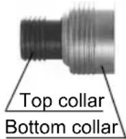
This Quick change chuck is designed to be used with Panasonic EY6535.
Top collar : To insert or to remove bit
Bottom collar : To attach or to detach Quick change chuck
Use 6.35 mm (1/4") hexagonal bits.
To ensure proper securement of the bit, use only hexagonal bits with 9.25mm (3 / 8^ ) detent. (Fig. 7)
CAUTION: Make sure the work environment is safe. When retracting bit from work material, Quick change chuck may detach if subjected to 50kg or more of pull force. Detachment will be sudden. Use care and avoid excessive force when retracting bit from work material.
-
Attaching Quick change chuck Attach the Quick change chuck by pulling the bottom collar forward and sliding the female detent on the bottom of the chuck to the square drive on the body. Release the bottom collar to make sure the Quick change chuck is firmly connected to the body.
-
Inserting the bit (Fig. 8) Pull the top collar of the Quick change chuck forward, then insert the bit. Release the bottom collar to make sure the bit is firmly connected to the chuck.
-
Removing the bit (Fig. 9) Pull the top collar of the Quick change chuck forward, then pull the bit.
CAUTION: Impact mechanism creates heat. Square drive and accessory may become very hot and may cause skin burns. To prevent skin burns, use work gloves and/or allow heated parts to cool down before handling.
- Detaching Quick change chuck Pull the bottom collar of the Quick change chuck forward to detach it.
Attaching or removing battery pack
-
To connect the battery pack: Insert the battery pack. It snaps into place to indicate proper connection.
-
To remove the battery pack: Press the two buttons on the sides of the battery pack. Slide the battery pack out of the tool body.
III. OPERATION
Switch Operation
- The speed increases with the amount of depression of the trigger. When beginning work, depress the trigger slightly to start the rotation slowly.
- A feedback electronic controller is used to give a strong torque even in low speed.
- The brake operates when the trigger is released and the motor stops immediately.
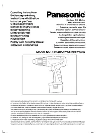
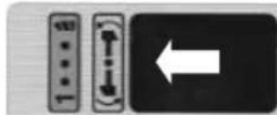
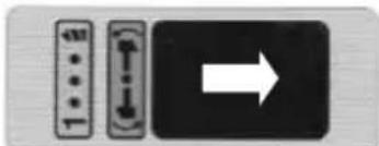
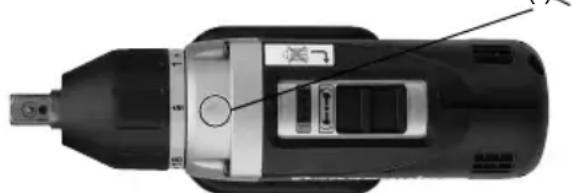
Reversing Lever Operation
(Forward (Switch lock, Reverse ())
CAUTION: Do not operate reversing lever until rotation of the spindle comes to a complete stop. Shifting during rotation of the chuck may damage the tool.
- For reverse rotation, set the lever to reverse. Check the direction of rotation before use.
- After use, set the lever to its center position (switch lock). (Fig. 10)
Clutch Torque Setting
Adjust the torque to one of the 18 possible settings or " position required to do the job.
CAUTION: Test the setting before actual operation. Set the scale at this mark (
CAUTION: To eliminate excessive temperature increase of the tool surface, do not operate the tool continuously, that is consecutively replacing the battery packs.
- Do not close up vent holes on the sides of the body during operation. Otherwise, the machine function is adversely affected to cause a failure
- Impact mechanism creates heat. Square drive and accessory become very hot. They may cause burns.
- Do not strain the tool(motor). This may cause damage to the unit.
-
Keep body or skin away from exhaust vent to avoid risk of being burned by hot air.
-
When operating with a Ni-MH battery pack, make sure the work place is well-ventilated.
For Appropriate use of Battery pack
Ni-MH Battery pack EY9230
- Charge the Ni-MH battery fully before storage in order to ensure a longer service life.
The ambient temperature range is between 0^ (32^) and 40^ (104^) .
If the battery pack is used when the battery temperature is below 0^ (32^) , the tool may fail to function properly. In that case, charge the battery until charging is completed for appropriate functioning of the battery.
- When battery pack is not in use, keep it away from other metal objects like: paper clips, coins, keys, nails, screws, or other small metal objects that can make a connection from one terminal to another.
Shorting the battery terminals together may cause sparks, burns or a fire. - When operating with a Ni-MH battery pack, make sure the place is well-ventilated.
Battery Pack Life
The rechargeable batteries have a limited life. If the operation time becomes extremely short after recharging, replace the battery pack with a new one.
Note: Use under extremely hot or cold conditions will reduce operating capacity per charge.
Battery Recycling
ATTENTION:
For environmental protection and recycling of materials, be sure that it is disposed of at an officially assigned location, if there is one in your country.
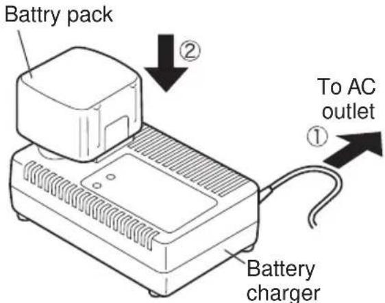
Charging
Note: When you charge the battery pack for the first time, or after prolonged storage, charge it for about 24 hours to bring the battery up to full capacity.
Battery charger (EY0110)
- Plug the charger into the AC outlet.
Note: Sparks may be produced when the plug is inserted into the AC power supply, but this is not a problem in terms of safety.
- Insert the battery pack firmly into the charger.
-
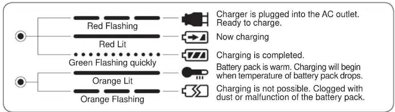
During charging, the charging lamp will be lit. When charging is completed, an internal electronic switch will automatically be triggered to prevent overcharging.
-
Charging will not start if the battery pack is warm (for example, immediately after heavy-duty operation).
The orange standby lamp will be lit until the battery cools down. Charging will then begin automatically.
- When charging is completed, the charging lamp will start flashing quickly in green color.
- When in any of the conditions that battery pack is too cool, or the battery pack has not been used for a long time, the charging lamp
is lit. In this case, charging takes longer to fully charge the battery pack, than the standard charging time.
-
If a fully charged battery pack is inserted into the charger again, the charging lamp light up. After several minutes, the charging lamp may flash quickly to indicate the charging is completed.
-
If the charging lamp does not light immediately after the charger is plugged in, or if after the standard charging time the lamp
Note: When charging a cool battery pack (below 5^ (41^) ) in a warm place, leave the battery pack at the place and wait for more than one hour to warm up the battery to the level of the ambient temperature. Otherwise battery pack may not be fully charged.
Cool down the charger when charging more than two battery packs consecutively.
- Do not insert your fingers into contact hole, when holding charger or any other occasions.
CAUTION: Do not use power source from an engine generator.
- Do not cover vent holes on the charger and the battery pack.
- Unplug the charger when not in use.
IV. LAMP INDICATIONS
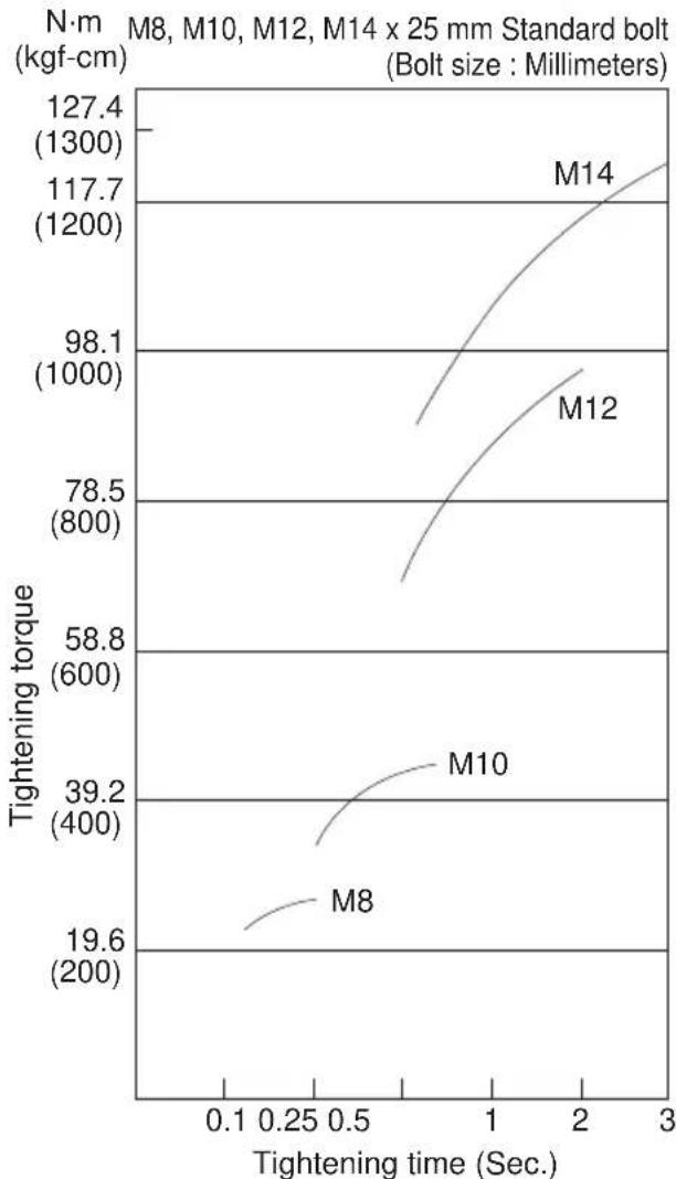
TIGHTENING TORQUE
- The power required for tightening a bolt will vary, according to bolt material and size, as well as the material being bolted. Choose the length of tightening time accordingly.
Reference values are provided below.
(They may vary according to tightening conditions.)
FACTORS AFFECTING TIGHTENING TORQUE
The tightening torque is affected by a wide variety of factors including the followings. After tightening, always check the torque with a torque wrench.
1) Voltage
When the battery pack becomes nearly discharged, the voltage decreases and the tightening torque drops.
Bolt Tightening Conditions
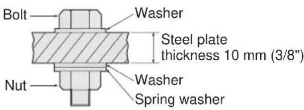
Tightening conditions
- The following bolts are used.
Standard bolt: Strength type 4.8
High tensile type 12.9
Explanation of the strength type 4.8
Bolt yield point
(80% of tensile strength)
471 N/mm² (48 kgf/mm²)
Bolt tensile strength 588 N/mm²
(60 kgf/mm²)
2) Tightening time
Longer tightening time results in increased tightening torque. Excessive tightening, however, adds no value and reduces the life of the tool.
3) Different bolt diameters
The size of the bolt diameter affects the tightening torque.
Generally, as the bolt diameter increases, tightening torque rises
4) Tightening conditions
- Tightening torque will vary, even with the same bolt, according to grade, length, and torque coefficient (the fixed coefficient indicated by the manufacturer upon production).
- Tightening torque will vary, even with the same bolting material (e.g. steel), according to the surface finish.
- Torque is greatly reduced when the bolt and nut start turning together.
5) Socket play
- Torque is lowered as the six-sided configuration of the socket of the wrong size is used to tighten a bolt.
6) Switch (Variable speed control trigger)
Torque is lowered if the unit is used with the switch not fully pulled out.
7) Effect of Connecting Adaptor
The tightening torque will be lowered through the use of a universal joint or a connecting adaptor.
V. ACCESSORIES
Use only bits suitable for size of drill's chuck.
Use Panasonic original Optional Keyless drill chuck (EY9X003E) and Quick change chuck (EY9HX110E) for maximum performance.
VI. SPECIFICATIONS
MAIN UNIT
| Model EY6535 | ||||
| Drill driver Mode | Impact mode(Caution: Do not use Keyless drill chuck for impact mode) | |||
| Maximun recommended capacities | Drilling | Wood drilling ø 27 | mm (1 - 1/16") | Not feasible |
| Metal drilling ø 13 | mm (1/2") | |||
| Screw driving | Machine screw M5 | Not feasible | ||
| Wood screw ø 6.8 | mm (17/64") | |||
| Tech screwø | 6 mm (15/64") | |||
| Coach screw (Lag bolt) | ø10 mm (3/8") | |||
| Bolt Fastening Not feasible | Standard Bolt: M12High Tensile Bolt: M10 | |||
| No load speed 0 - 650 /min (rpm) 0 - 2200 /min (rpm) | ||||
| Max Torque 22.6 Nm (230 kgf-cm) | 127.5 Nm (1300 kgf-cm)at high tensile bolt fastening | |||
| Clutch Torque | Approx.1.0 Nm (10 kgf-cm, 8.7 in-lbs.) -5.4 Nm (55 kgf-cm, 47.7 in-lbs.) | - | ||
| Impact per minute | - | 0 - 3300 /min (ipm) | ||
| Motor | DC Motor 15.6V | |||
| Square drive | 12.7 mm (1/2") square drive with ball detent | |||
| Weight (with battery pack) | 2.2 kg ( 4.8 lbs.) | |||
| Overall length | 216 mm ( 8 - 1/2") | |||
KEYLESS DRILL CHUCK
| Model | EY9X003E |
| Chuck Capacity | 1.6 mm - 13 mm (1/16" - 1/2") |
BATTERY PACK
| Model EY9230 | |
| Storage battery | Ni-MH Battery |
| Battery voltage | 15.6V DC (1.2V x 13 cells) |
BATTERY CHARGER
| Model | EY0110 | ||||||
| Electrical rating | See the rating plate on the bottom of the charger. | ||||||
| Weight | 0.78 kg, (1.72 lbs.) | ||||||
| Charging Time | 7.2 V | 9.6 V | 12 V | 15.6 V | 18 V | 24 V | |
| 1.2Ah | EY9066, EY9066 | EY9080, EY9086 | EY9001, EY9006 | ||||
| 20min. | |||||||
| 1.7Ah | EY9180, EY9182 | EY9101 | |||||
| 25min. | |||||||
| 2.0Ah | EY916830min. | EY9106 | EY9136 | EY911760min. | |||
| 3.0Ah | EY9200 | EY9230 | EY921090min. | ||||
| 3.5Ah | EY9201 | EY9231 | EY925165min. | ||||
Note: This chart may include models that are not available in your area.
Please refer to the catalogue.
CAUTION: This Panasonic Multi Drill & Driver is designed to use only battery pack type EY9230, EY9136. Use with other battery pack type may damage the tool and the battery, and may result in the risk of fire and personal injury.
ONLY FOR U.K.
VII .ELECTRICAL PLUG INFORMATION
FOR YOUR SAFETY PLEASE READ THE FOLLOWING TEXT CAREFULLY
This appliance is supplied with a moulded three pin mains plug for your safety and convenience.
A 3 amp fuse is fitted in this plug.
Should the fuse need to be replaced please ensure that the replacement fuse has a rating of 3 amp and that it is approved by ASTA or BSI to BS1362.
Check for the ASTA mark or the BSI mark on the body of the fuse.
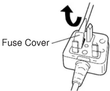
If the plug contains a removable fuse cover you must ensure that it is refitted when the fuse is replaced.
If you lose the fuse cover the plug must not be used until a replacement cover is obtained.
A replacement fuse cover can be purchased from your local Panasonic Dealer. IF THE FITTED MOULDED PLUG IS UNSUITABLE FOR THE SOCKET OUTLET IN YOUR HOME THEN THE FUSE SHOULD BE REMOVED AND THE PLUG CUT OFF AND DISPOSED OF SAFELY. THERE IS A DANGER OF SEVERE ELECTRICAL SHOCK IF THE CUT OFF PLUG IS INSERTED INTO ANY 13 AMP SOCKET.
If a new plug is to be fitted please observe the wiring code as shown below.
If in any doubt please consult a qualified electrician.
IMPORTANT: The wires in this mains lead are coloured in accordance with the following code: Blue: Neutral Brown:Live
As the colours of the wire in the mains lead of this appliance may not correspond with the coloured markings identifying the terminals in your plug, proceed as follows.
The wire which is coloured BLUE must be connected to the terminal in the plug which is marked with the letter N or coloured BLACK.
The wire which is coloured BROWN must be connected to the terminal in the plug which is marked with the letter L or coloured RED.
Under no circumstances should either of these wires be connected to the earth terminal of the three pin plug, marked with the letter E or the Earth Symbol 1三
How to replace the fuse: Open the fuse compartment with a screwdriver and replace the fuse and fuse cover if it is removable.
This apparatus was produced to BS800.
— MEMO —
Nøkkelfri drillchuck
| Modell | EY9X003E |
| Chuckkapasitet | 1,6 mm - 13 mm (1/16" - 1/2") |
BATTERIE
| Modell EY9230 | |
| Lagringsbatteri | Ni-MH batteri |
| Batterispenning | 15,6 V likestrøm (1,2 V × 13 celler) |
BATTERILADER
| Modell | EY0110 | ||||||
| Elektrisk merking | Se merkeplaten på bunnen av utladeren. | ||||||
| Vekt | 0,78 kg, (1,72 lbs.) | ||||||
| Ladetid | 7,2 V | 9,6 V | 12 V | 15,6 V | 18 V | 24 V | |
| 1,2Ah | EY9065, EY9066 | EY9080, EY9086 | EY9001, EY9006 | ||||
| 20 min. | |||||||
| 1,7Ah | EY9180, EY9182 | EY9101 | |||||
| 25 min. | |||||||
| 2,0Ah | EY916830 min. | EY9106 | EY9136 | EY911760 min. | |||
| 3,0Ah | EY9200 | EY9230 | EY921090 min. | ||||
| 3,5Ah | EY9201 | EY9231 | EY925165 min. | ||||
AKUN IRROTUS JA KIINNITYS
Matushita Electric Works, Ltd.
Osaka, Japan
No.1 EN.GN.FR.IT.ND.ES.DN.SW.NR.FN
EY971065354 H1701 Printed in Japan