SP 8.0 - Fitness Equipment COMPEX - Free user manual and instructions
Find the device manual for free SP 8.0 COMPEX in PDF.
| Product type | Wireless muscle and nerve stimulator |
| Brand | Compex |
| Model | SP 8.0 |
| Number of channels | 4 independent and individually adjustable channels |
| Remote control power supply | Rechargeable Lithium Polymer battery 3.7 V / ≥ 1500 mAh |
| Module power supply | Rechargeable Lithium Polymer battery 3.7 V / ≥ 450 mAh |
| Mains adapter | 5 V / 3,5 A, reference 64902X |
| Maximum pulse intensity | 120 mA |
| Pulse duration | 50 to 400 μs |
| Pulse frequency | 1 to 150 Hz |
| Integrated technologies | MI-Scan, MI-TENS, MI-Range, MI-Autorange, MI-Action |
| Program functions | Favorites, Programs by category, Custom goals |
| Connectivity | Wireless 2.4 GHz ISM, synchronization via USB cable |
| Kit contents | Remote control, 4 modules, charging station, charger, electrodes (small and large), USB cable, quick start guide, carrying case |
| Maintenance | Clean with a soft cloth and alcohol-based detergent without solvents. Do not disassemble. |
| Storage conditions | Temperature: -20 °C to 45 °C, relative humidity max. 75%, pressure 700-1060 hPa |
| Operating conditions | Temperature: 5 °C to 40 °C, relative humidity 30-75%, pressure 700-1060 hPa |
| Standards | CE, MD, compliant with European directives, IEC 60601-1, IEC 60601-1-2, IEC 60601-2-10 |
| Warranty | See included manual |
| Weight | Not specified in the manual |
| Dimensions | Not specified in the manual |
Frequently Asked Questions - SP 8.0 COMPEX
User questions about SP 8.0 COMPEX
0 question about this device. Answer the ones you know or ask your own.
Ask a new question about this device
Download the instructions for your Fitness Equipment in PDF format for free! Find your manual SP 8.0 - COMPEX and take your electronic device back in hand. On this page are published all the documents necessary for the use of your device. SP 8.0 by COMPEX.
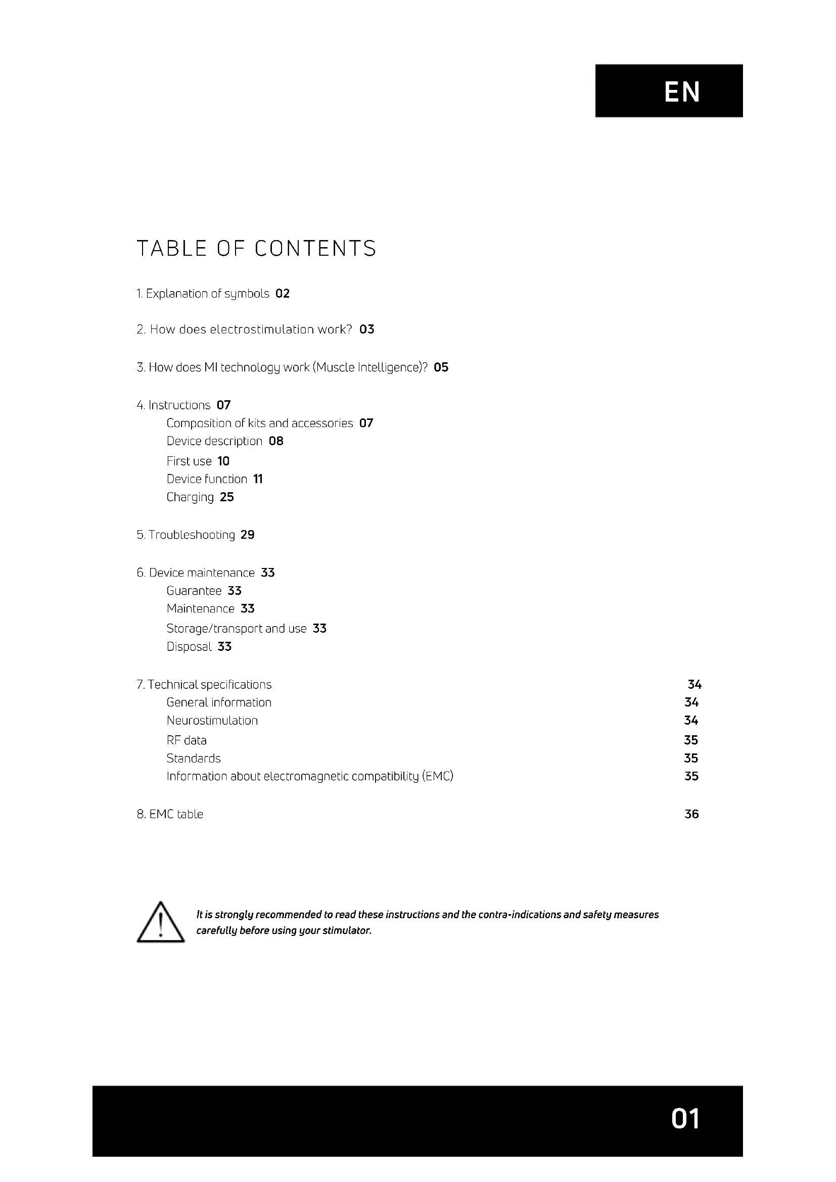
USER MANUAL SP 8.0 COMPEX
- Explanation of symbols 02
- How does electrostimulation work? 03
- How does MI technology work (Muscle Intelligence)? 05
- Instructions 07
Composition of kits and accessories 07
Device description 08
First use 10
Device function 11
Charging 25
5.Troubleshooting 29
6. Device maintenance 33
Guarantee 33
Maintenance 33
Storage/transport and use 33
Disposal 33
- Technical specifications 34
General information 34
Neurostimulation 34
RF data 35
Standards 35
Information about electromagnetic compatibility (EMC) 35
- EMC table 36
It is strongly recommended to read these instructions and the contra-indications and safety measures carefully before using your stimulator.
1. EXPLANATION OF SYMBOLS
| See the instructions | MD | MD medical device | |
| The stimulator is a category II device with built-in power supply and type BF applied parts. | SN | SN Serial number | |
| Manufacturer's name and address and date of manufacture | UDI | UDI Unique Device Identification | |
| Name and address of approved representative in the European Community | Best used by | ||
| This device must be separated from household waste and sent to special collection facilities for recycling and recovery | Origin and date of manufacture | ||
| The stand-by button is multi-functional | Relative humidity | ||
| Protect from sunlight Temperature | |||
| Store in a dry place Atmospheric pressure | |||
| IP22 on the unit | IP 22 on the unit means the protection is effective against ingress of foreign solid objects (diameter greater than 12.5 mm) and against ingress of dripping water (when tilted up tp 15°). | CE 2797 | CE mark with notify body number |
| LATEX | Latex-free | ||
| REF | Reference number | ||
| LOT | Batch number |
2. HOW DOES ELECTROSTIMULATION WORK?
Electrostimulation involves stimulating nerve fibres by electrical impulses transmitted by electrodes. The electrical impulses produced by Compex stimulators are high-quality impulses that are safe, comfortable and effective and stimulate various types of nerve fibres:
- Motor nerves to stimulate a muscle response referred to as electrical muscle stimulation (EMS).
- Certain types of sensitive nerve fibres to obtain analgesic effects or pain relief.
1. STIMULATION OF MOTOR NERVES (EMS)
With voluntary activity, the brain orders muscles to contract and a command is then sent to nerve fibres in the form of an electrical signal. This signal is then sent to muscle fibres, which contract. The principle of electrostimulation correctly reproduces the process involved in a voluntary contraction. The stimulator sends an electrical impulse to nerve fibres to excite them. This excitation is then transmitted to muscle fibres and results in a mechanical response (= a twitch). This is the basic requirement for muscular contraction. The muscular response is to all intents and purposes identical to the muscular work controlled by the brain. In other words, the muscle does not distinguish between a command sent by the brain or the stimulator.
Programme settings (number of impulses per second, duration of contraction, rest time, total programme duration) subject the muscle to various types of workout, depending on the muscle fibre. Various types of muscle fibres can be identified depending on their respective contraction speeds: slow, intermediate and rapid fibres. A sprinter clearly has more rapid fibres and a marathon runner has more slow fibres. With good knowledge of human physiology and perfect control of stimulation settings in the various programmes, muscular workout can be very accurately directed to achieve the desired objective (muscular strengthening, increased blood circulation, firming, etc.).
2. STIMULATION OF SENSORY NERVES
Electrical impulses can also excite sensory nerve fibres to obtain analgesic effects or pain relief.
Stimulating tactile sensory nerve fibres blocks pain being transmitted to the nervous system. Stimulating another type of sensory fibre increases the production of endorphins and therefore reduces pain. With pain relief programmes, electrostimulation can be used to treat acute or chronic localised pain and muscle pain.
Note: Do not use pain relief programmes for an extended period without medical advice.
BENEFITS OF ELECTROSTIMULATION
Electrostimulation is a very effective method for making muscles work:
with a significant improvement in various muscle qualities
with no cardiovascular or mental fatigue
with limited stress exercised on joints and tendons. Electrostimulation thereby enables more muscular workout than voluntary activity.
For optimum results, Compex recommends supplementing your electrostimulation sessions with other exercise, such as:
- regular physical exercise
balanced and healthy diet
balanced life style
3. HOW DOES MI TECHNOLOGY WORK (MUSCLE INTELLIGENCE)?
N.B.: The activation/deactivation of MI functions is performed via the Settings menu
MI-SCAN
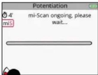
Just before starting a workout session, the MI-scan function probes the chosen muscle group and automatically adjusts the stimulator settings to the excitability of this area of the body, depending on your physiology.
This function results in, at the start of the programme, a short test sequence during which measurements are taken.
At the end of the test, intensities must be increased to start the programme.
MI-TENS
The MI-tens function limits unwanted muscle contractions in painful areas.
With each intensity increase, a test phase occurs and if a muscular contraction is detected, the device automatically reduces the intensity of the stimulation.
This function is only accessible in the TENS, Epicondylitis and Tendinitis programmes.
MI-RANGE
The MI-range function allows the user to select the ideal level of stimulation intensity for recovery, massage, capillarisation or even muscle pain programmes.
At the beginning of the programme, the device prompts the user to increase stimulation intensity. During this increase, the device analyses the response of each stimulated muscle, and deduces their optimal level. As soon as a muscle reaches its optimal level, the related channel is automatically deselected and the stimulation intensity cannot be increased. To recover control, simply re-select the channel in question and raise or lower the stimulation intensities.
MI-AUTORANGE
The MI-autorange function pursues the same objective as MI-range except that in this case everything is done automatically.
At the beginning of the programme, a single press of the up key of the multifunction pad allows the device to automatically increase the stimulation intensities until it detects the ideal level of intensity. Pressing the down key of the multifunction pad cancels the MI-autorange function. The device then goes into manual mode and intensities must be managed by the user.
MI-ACTION
The MI-action function allows you an electro-induced contraction to be initiated by means of a voluntary action. Thus the electro-induced contraction is perfectly controlled, the workout becomes more comfortable, more thorough and more complete.
At the end of each active rest phase the remote control emits a beep. From this point the start of voluntary contraction is possible. If no voluntary contraction has occurred after a certain period of time, the device will automatically pause.
This work mode is available only for programmes inducing powerful muscle contractions.
N.B.: To function properly, the MI-action function needs good muscle twitches during the active rest phase. If they are not significant enough, the device emits beeps and a + sign appears on the channels. Similarly, in order to render these twitches possible, it is imperative that muscles be well relaxed during the rest phase. At the end of each contraction phase, it is necessary to ensure that you return to a position allowing for best muscle relaxation.
The table below shows which functions are available with each device.
| SP 6.0 SP 8.0 FIT 5.0 | |||
| MI-SCAN | ✓ | ✓ | ✓ |
| MI-TENS | - | ✓ | - |
| MI-RANGE | ✓ | - | ✓ |
| MI-AUTORANGE | - | ✓ | - |
| MI-ACTION | - | ✓ | - |
4. INSTRUCTIONS
COMPOSITION OF KITS AND ACCESSORIES
| SP 6.0 SP 8.0 / WOD FIT 5.0 | ||||||
| REF QTY | REF QTY | REF QTY | ||||
| REMOTE CONTROL | 001047 1 | 001046 / 001046CF | 1 001048 1 | |||
| MODULES | 001061 4 | 001061 / 001061CF | 4 001055 2 | |||
| DOCKING STATION | 001068 1 001068 1 001073 1 | |||||
| CHARGER | 64902X 1 64902X 1 64902X 1 | |||||
| BAG OF SMALL 5X5 ELECTRODES | 42215-8 1 42215-8 1 42215 1 | |||||
| BAG OF LARGE 5X10 ELECTRODES, 2 SNAP | 42216-4 1 42216-4 1 42216 1 | |||||
| BAG OF LARGE 5X10 ELECTRODES, 1 SNAP | 42222-4 1 42222-4 1 42222-4 1 | |||||
| QUICK START GUIDE | 885625 1 885625 1 885625 1 | |||||
| CARRY CASE | 680043 1 | 680042 / 680043 + 680042 | 1 680043 1 | |||
| REMOTE CONTROL PROTECTION SLEEVE | NA NA 00 1094 1 NA NA | |||||
| USB CABLE | 601163 1 601163 1 601163 1 | |||||
| USER MANUAL | 4528182 1 4528182 1 4528 182 1 | |||||

Only use this device with cables, electrodes, battery, power adaptor and accessories recommended by Compex.
DEVICE DESCRIPTION
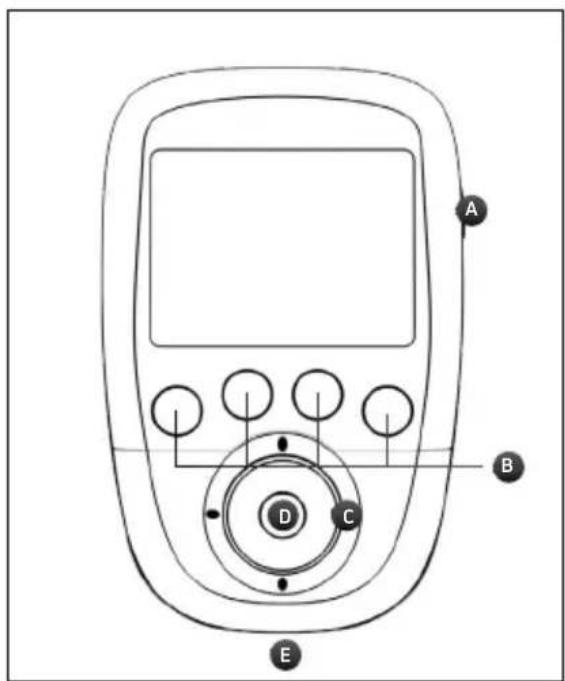
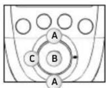
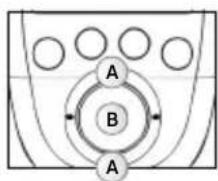
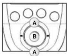
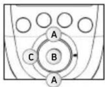
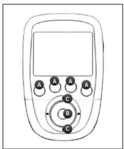
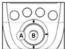
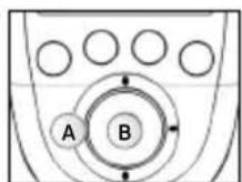
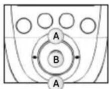
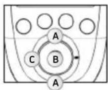
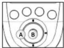
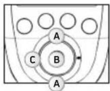
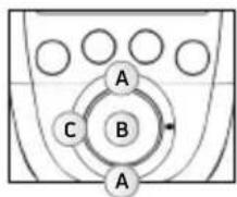
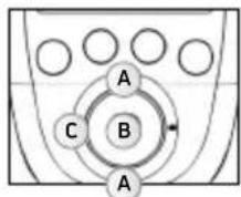
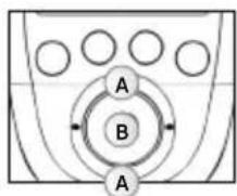
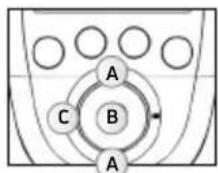
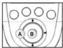
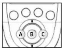
REMOTE CONTROL
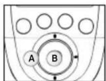
A - On/Off button (press briefly to turn on, hold down for more than 2 sec. to turn off)
B - 4 buttons for the selection/deselection of the stimulation channel
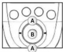
C - Multifunction pad (up-down-left-right) to navigate the interface and increase or decrease the level of stimulation intensity of the selected channels
D - Confirm button
E - Plug for the USB cable or the docking station connector
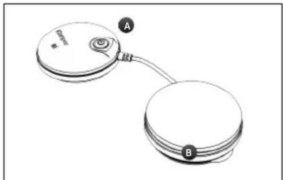
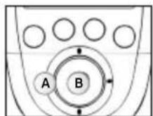
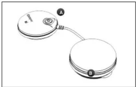
MODULE
A - On/Off button (press briefly to turn on, press and hold down to turn off)
Flashing green LED: Ready
Flashing yellow LED: In stimulation
B - Groove for winding the cable
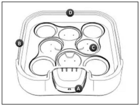
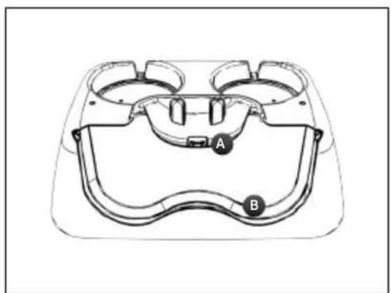
DEVICE DESCRIPTION


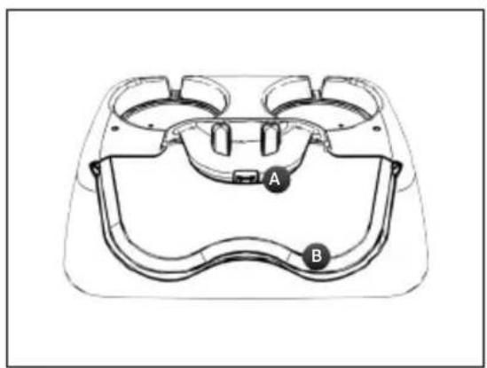
SP 6.0 AND 8.0 DOCKING STATION
A - Remote control charging connector
B - Notch to open the lid of the docking station
C - Location for positioning the modules to be recharged
D-Charger plug
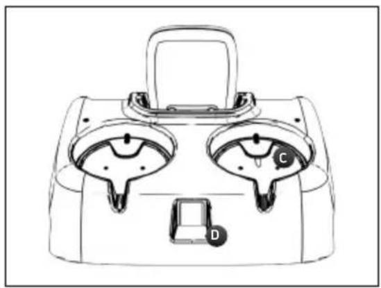
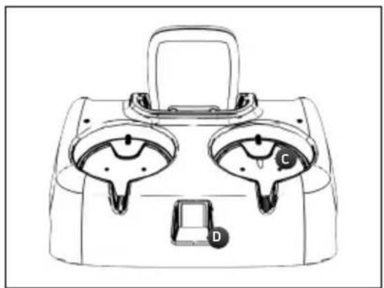
FIT 5.0 DOCKING STATION
A - Remote control charging connector
B - Location for positioning the modules
C - Location for positioning the modules to be recharged
D - Charger plug
FIRSTUSE
When using the device for the first time, the following steps must be followed:
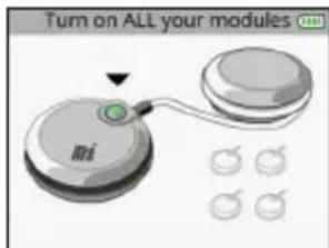
1. Select language

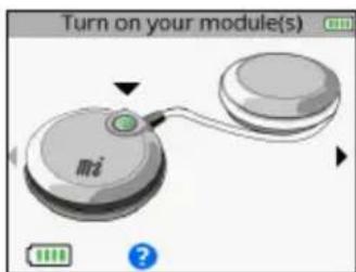
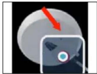
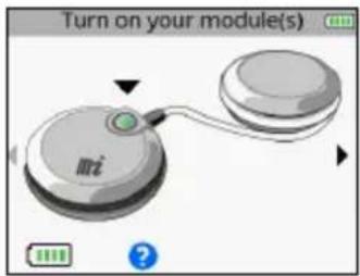
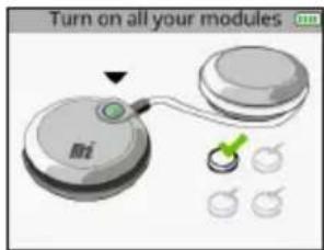
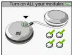
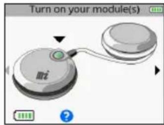
- Turn on all modules in order to pair them with the remote control.

Once a module is turned on and recognized by the remote control, a check appears on the module.
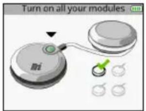
When all modules are paired all check marks appear.
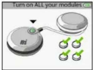
N.B.: This pairing procedure is to be performed only once.
DEVICE FUNCTION
N.B.: The following screens are generic examples but they work in the same way regardless of the device that you have.
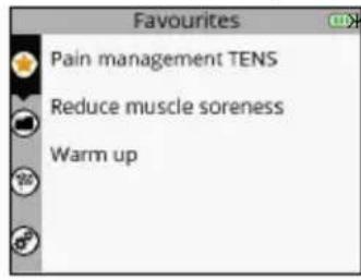
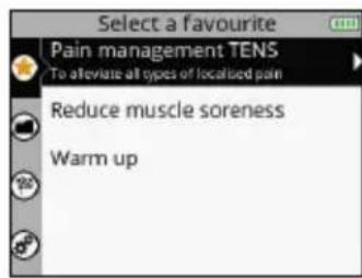
HOW TO ACCESS FAVOURITES
The Favourites menu displays the last programmes done. You need only have one programme in the Favourites menu to become directly accessible after turning on the device.
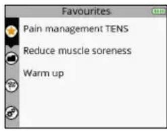

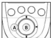
A Select the Favourites menu
B Confirm your selection
The programmes done will automatically be placed in the Favourites menu. The Favourites menu can contain up to 10 programmes. If new programmes are done, the old ones will automatically be removed from the list of favourites.
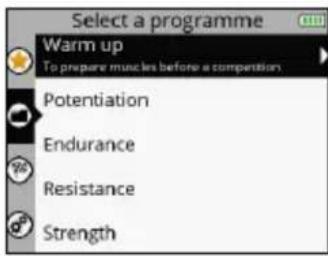
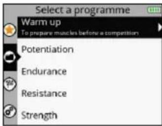
1. SELECT A PROGRAMME


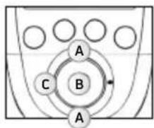
A Select the desired favourite programme
B Confirm your selection
C Return to the previous step
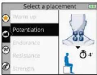
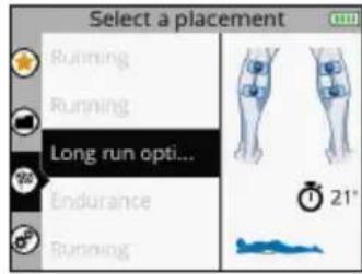
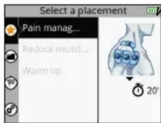
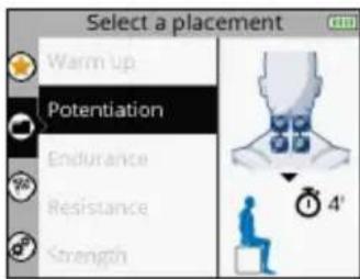
2. SELECT ELECTRODE PLACEMENT

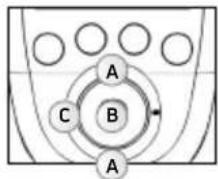
A Select the desired electrode placement
B Confirm your selection
C Return to the previous step
The placement of electrodes selected during the programme appears. It is possible to scroll through other electrode placements.
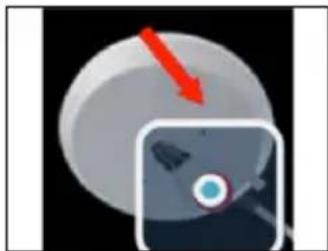
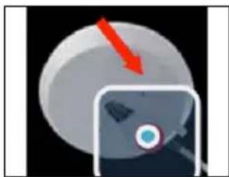
3. CONNECT THE MODULES TO THE ELECTRODES
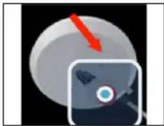
Stick the electrodes to your skin. The module is attached to the electrode from the side. Slide the module onto the electrode's snap until it clips into place.
4. TURN ON THE MODULES
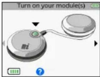

A Return to the previous step
B Confirm your selection
To launch the programme, see the section entitled "Start a stimulation programme."
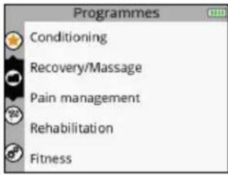
HOW TO ACCESS PROGRAMMES
For more information on programmes, connect to: www.compex.info
The Programmes menu displays the programme categories.
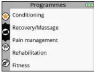
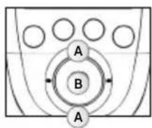
A Select the Programmes menu
B Confirm your selection
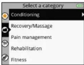
1. SELECT A CATEGORY
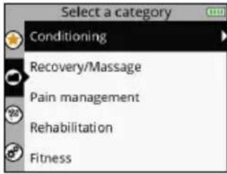
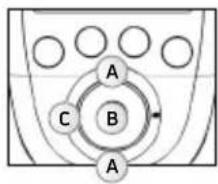
A Select the desired programme category
B Confirm your selection
C Return to the previous step
2. SELECT A PROGRAMME
A Select the desired programme
B Confirm your selection
C Return to the previous step
3. SELECT ELECTRODE PLACEMENT
A Select the desired electrode placement
B Confirm your selection
C Return to the previous step
4. CONNECT THE MODULES TO THE ELECTRODES
Stick the electrodes to your skin. The module is attached to the electrode from the side. Slide the module onto the electrode's snap until it clips into place.
5. TURNOTN THE MODULES
A Return to the previous step
B Confirm your selection
To launch the programme, see the section entitled "Start a stimulation programme."
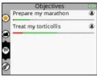
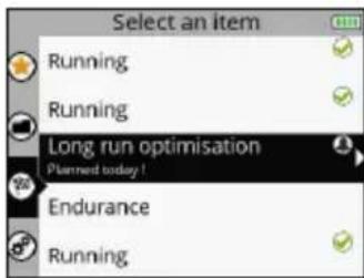
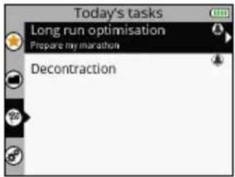
HOW TO ACCESS OBJECTIVES
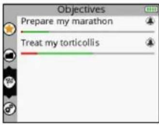
The Objectives menu displays the objectives downloaded from your personal account (see section entitled "Creating your personal account").
N.B.: The Objectives menu is only available for the SP 8.0 device.
A Select the Objectives menu
B Confirm your selection
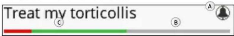
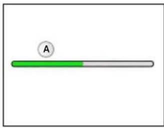
The progress bar under the objective shows the progress of the objective and what remains to be done. The bell indicates that there is an element of the objective to perform today.
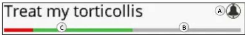
A Indicates an element of the objective to perform today
B What remains to be done
C What has already been accomplished?
- What has been completed appears in green
- What has not been completed appears in red
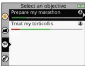
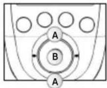
1. SELECT AN OBJECTIVE
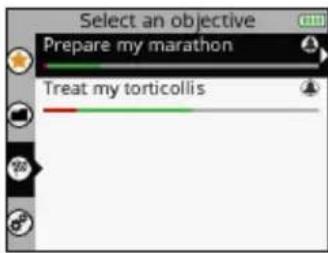

A Select the desired objective
B Confirm your selection
C Return to the previous step
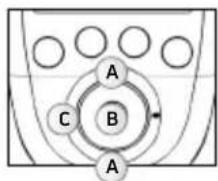
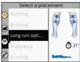
2. SELECT AN ELEMENT TO DO
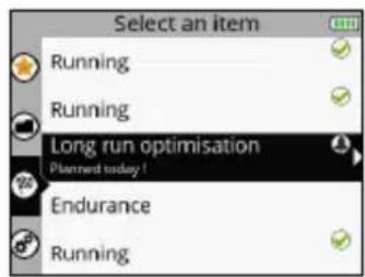
A Select the desired element
B Confirm your selection
C Return to the previous step
The element to do can be a programme or a task. The element to do is selected by default, but it is possible to select another.
The next to a programme or a task signifies that it has been done.
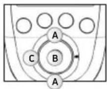
3. SELECT ELECTRODE PLACEMENT

A Select the desired electrode placement
B Confirm your selection
C Return to the previous step
N.B.: In most cases a different electrode placement cannot be selected because it is directly linked to the objective.
4. CONNECT THE MODULES TO THE ELECTRODES
Stick the electrodes to your skin. The module is attached to the electrode from the side. Slide the module onto the electrode's snap until it clips into place.

5. TURNOTN THE MODULES
A Return to the previous step
B Confirm your selection
To launch the programme, see the section entitled "Start a stimulation programme."
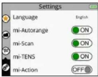
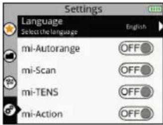
HOW TO ACCESS SETTINGS
The Settings menu enables certain elements to be configured such as backlighting, volume, language, etc. Some settings are not available in all devices.
A Select the Settings menu
B Confirm your selection
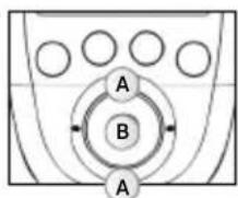
1. SELECT A SETTING
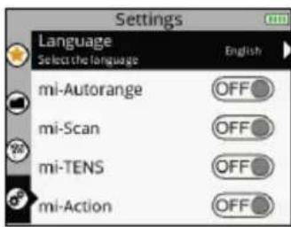
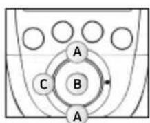
A Select the desired setting
B Confirm your selection
C Return to the previous step
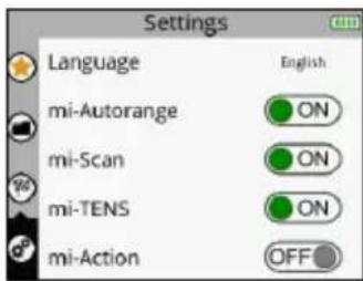
Language: Allows you to change the device's language
MI-autorange:Turns the MI-autorange function on (ON) or off (OFF)
MI-range:Turns the MI-range function on (ON) or off (OFF)
MI-scan:Turns the MI-scan function on (ON) or off (OFF)
MI-tens:Turns the MI-tens function on (ON) or off (OFF)
MI-action:Turns the MI-action function on (ON) or off (OFF)
N.B.: For an explanation of MI functions see the section entitled "3. How does MI technology work?"
Cycles:Turns the Cycles function on (ON) or off (OFF)
The Cycles function is for people who are already accustomed to electrostimulation and want to perform several training cycles. If the Cycles function is turned on (ON) an additional screen will appear for certain programmes (programmes inducing powerful muscle contractions) enabling the training cycle to be selected.
The cycle logic refers to the workload performed by electrostimulation. And just like a normal workout, one has to start with an amount of work then increase it over the course of the cycles. Thus, it is recommended starting with the 1st cycle and going on to the next level when the cycle is finished, normally after 4 to 6 weeks of stimulation based on 3 sessions per week. It is also important to have reached significant stimulation intensities in sessions before going on to another cycle.
Power saving: Turns the Power saving function on (ON) or off (OFF). Decreases the intensity and the backlighting time.
Sound: Turns the Sound function on (ON) or off (OFF).
Contraction sound: Turns the contraction arrival warning sound on (ON) or off (OFF).
Set time: Allows you to set the time on the device.
Set date: Allows you to set the date on the device.
Pair a new module: Enables a new module to be paired to the remote control.
Reset the device: Enables the device to be re-set and return to the basic settings (Favourites deleted, Objectives cleared, Default settings).
System info: Enables information related to the device to be viewed.
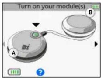
START A STIMULATION PROGRAMME
Before beginning any stimulation programme, you must turn the modules on.


A Return to the previous step
B Confirm your selection and start the programme
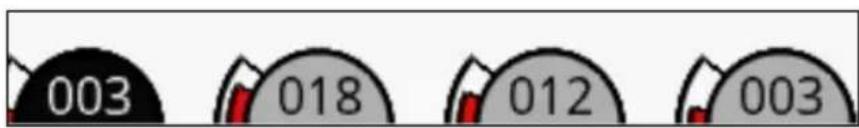
To turn on the modules, press their respective On/Off button. As soon as the module is turned on, its battery level appears on the screen. Turn on the number of modules desired according to the electrode placement selected. As soon as a sufficient number of modules is turned on, a small arrow appears on the right of the screen.
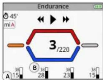
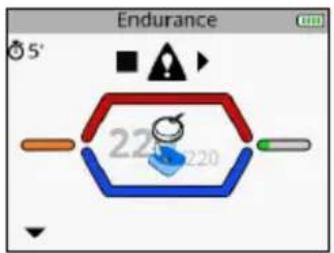
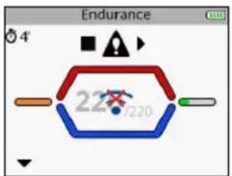
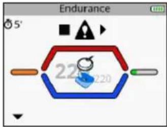
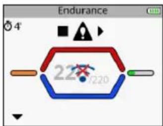
If the MI-scan function is activated, the programme starts with a short sequence during which measurements are taken. For the duration of the measurement test, it is important to stand still and be perfectly relaxed. Once the test is completed, the programme can start. Stimulation always starts at 000.

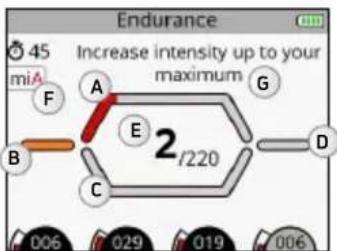
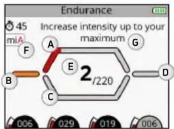
A Contraction phase
B Warm up phase
C Active rest phase
D Relaxation phase
E Number of contractions performed / Total number of contractions
F Indication of the active MI function
6 Pop-up help indicating information or actions to be taken
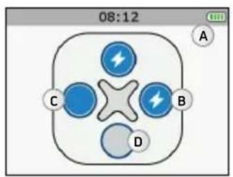
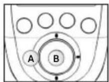
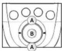
A Select the channels on which to act. When a channel is active the LED button emits a strong blue light.
B Pause
C Increase or decrease the stimulation intensities on the selected channels
Increase the stimulation intensities on the selected channels.
By default, all of the channels are active at the beginning of the session. To deselect a channel, simply press the corresponding button.
In this case only channel 1 is active. Any change of intensity will only be performed on channel 1.
Depending on the programme, the diagram on the middle of the screen can change.
CONTRACTION/ACTIVE REST PROGRAMME
These programmes always begin with a warm-up phase. After this warm-up phase, a contraction cycles phase followed by active rest occurs (the number of cycles depends on the programme) and when all cycles are completed, the programme ends with a relaxation phase.
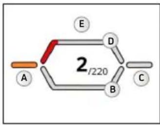
A Warm up phase
B Active rest phase
C Relaxation phase
D Contraction phase
E Work phase which consists of a contraction/active rest cycle
MASSAGE, RECOVERY TYPE PROGRAMME
These programmes consist of a single phase and have no contraction/active rest cycle. These are recovery, massage, capillarisation, or even pain type programmes. During this type of programme, frequency variations can occur.

A Work phase
CONTINUE A STIMULATION PROGRAMME

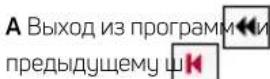
A Skip the current phase or exit the

The stimulation session
C Skip the current phase
or exit the
programme

A Average stimulation intensity
B Maximum stimulation intensity
By pressing on the central button of the remote control or on the On/Off button of one of the modules during the stimulation, the device goes into pause. At this point it is possible to skip the current phase or exit the programme.
Depending on the programme, maximum and average intensities statistics may appear.
N.B.: The session restarts with intensities equal to 80% of those used prior to the interruption.
END A STIMULATION PROGRAMME
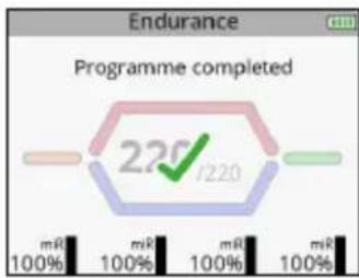
At the end of the session a screen with a check mark appears. Pressing on any button returns you to the Favourites menu. To turn off the device, hold down the remote control's On/Off button for 2 seconds. This will also result in turning off all modules.
Depending on the programme, maximum and average intensities statistics may appear.
CHARGING
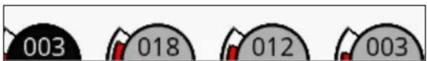
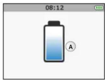
BATTERY LEVEL INDICATION
A Module battery level.
B Remote control battery level
Module battery levels appear just prior to launching the stimulation session. The remote control battery level is always visible in the top right corner.
CONNECT THE DOCKING STATION
Connect the AC adapter supplied with your device to the docking station and then plug it into a power outlet. It is strongly recommended that you fully charge the remote control batteries and modules before first use in order to improve its performance and life expectancy.
CHARGE THE REMOTE CONTROL AND THE MODULES
At the end of the stimulation session, it is strongly recommended that you store the remote control and modules in the docking station to charge the elements.
SP6.0,8.0FIT5.0
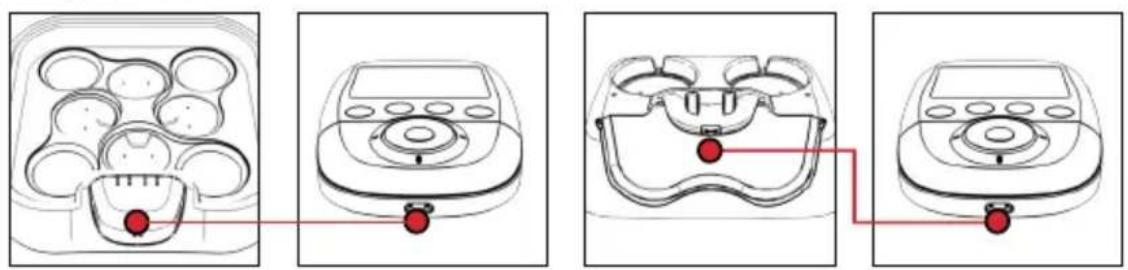
In order to do so, place the remote control on its connector.
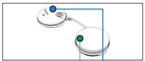
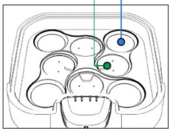
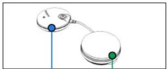
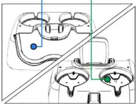
Then place the modules in the slots provided for this purpose.
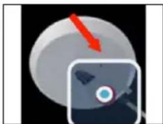
To do so, place the pod without the On/Off button (the green one in the figure) in the location indicated in green and the other pod in the location indicated in blue. Do the same for the other modules.
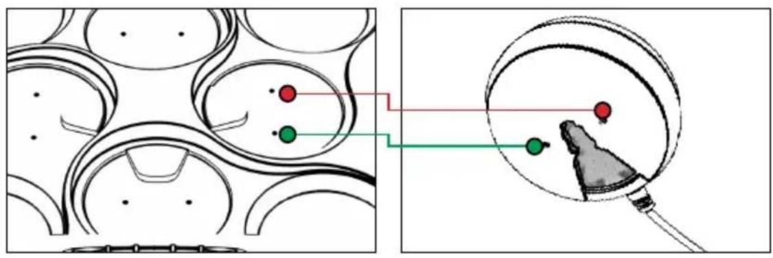
The pod without the On/Off button must fit on the small connectors. A magnet as well as the small vertical mark on the hull of the pod helps to position the pod correctly in its slot. When it is positioned correctly you should hear a click.
SP 6.0,8.0 FIT 5.0
A Remote control battery charging
B Module charging
C Module charged
D No module present
A Remote control battery charging

LED flashing: Module charging
LED full: Module charged
When a module is placed on the docking station it appears on the remote control's screen.
As soon as the remote control and modules are fully charged, they go into standby mode.
When a module is placed on the docking station, the green LED indicates the module's status.
As soon as the remote control and modules are fully charged, they go into standby mode.
N.B.: If the device is not used for an extended period, we recommend that you charge the batteries to 50% of their capacity every 3 months.
CREATE YOUR PERSONAL ACCOUNT
To take advantage of all of your device's capabilities you must first create an account at the following address www.compexwireless.com and follow the instructions on the website.
Functions associated with the SP 8.0
- Access a training schedule
- Download preset objectives directly into the device
- Create your own objectives and download them directly into the device
- Upload the device's history (stimulation programmes done) to the website
As soon as an objective is downloaded into the remote control, the first screen that appears when the device is switched on displays the daily tasks to be performed.

Functions associated with the SP 6.0 and FIT 5.0
- Access a training schedule
- Upload the device's history (stimulation programmes done) to the website
5. TROUBLESHOOTING
ELECTRODE FAULT
The remote control displays the symbol of an electrode and a disconnected module and an arrow flashes on the channel in question (in this case, channel 1).
- Ensure that the electrodes are properly connected to the module.
- Check to see if electrodes are old, worn and/or if contact is poor: try using new electrodes.
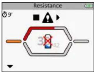
MODULE OUT OF RANGE
The remote control displays the out of range symbol and an arrow flashing on the channel where the problem was detected (in this case, channel 1).
- Check to make sure that the module and the remote control are less than 2 metres away from each other.
- Make sure you are not in an isolated area with no obstacle to reflect the signal from the remote control.
Make sure you are in an area that enables the signal to be reflected from the remote control.
SYNCHRONIZATION PROBLEM
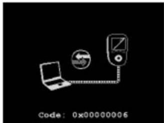
If the synchronization process was discontinued or cannot run successfully for any reason (remote control disconnected, power failure, etc.) the remote control may, in some cases, display this screen.
- Reconnect the remote control to the computer and restart the synchronization process.
BEHAVIOUR OF THE MODULE'S LED
The LED alternately flashes green and red: the module is out of range or not recognized by the remote control.
- Ensure the remote control is on.
- Ensure that the module and the remote control are less than 2 metres away from each other.
The LED is still red.
- Ensure the module is charged.
- Try to restart the remote control and modules.
- If despite this the LED is still red, contact customer service provided and approved by Compex.
The LED does not turn on.
- Ensure the module is charged.
If despite this the LED still does not turn on, contact customer service provided and approved by Compex.
MODULE UNCHARGED
During the stimulation a module may be uncharged. In this case the symbol for an uncharged battery appears and an arrow flashing on the channel where the problem was detected (in this case, channel 1).
- Stop the stimulation and recharge the uncharged module.
- Abandon the uncharged module and continue the stimulation session without it.
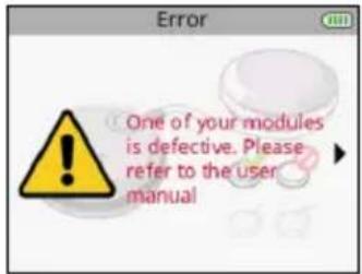
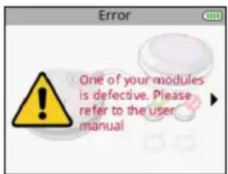
THE MODULE WILL NOT PAIR WITH THE REMOTE CONTROL

At the time of first use, if the remote control is unable to pair all modules, an error message may appear.
- Ensure that the module is charged, and repeat the pairing step.
If despite this the message returns, contact customer service provided and approved by Compex.
STIMULATION DOES NOT PRODUCE THE USUAL SENSATION
- Check that all settings are right and check electrodes are properly positioned.
- Change the positioning of the electrodes slightly.
STIMULATION CAUSES DISCOMFORT
- Electrodes lose their adhesive capacity and no longer provide adequate contact with skin.
- Electrodes are worn and must be replaced.
- Change the positioning of the electrodes slightly.
THE DEVICE IS NOT WORKING
- Ensure that the remote control and modules are charged.
Try to restart the remote control and modules.
If despite this the device still does not work, contact customer service provided and approved by Compex.
6. DEVICE MAINTENANCE
GUARANTEE
See the attached leaflet.
MAINTENANCE
Your stimulator does not require any calibration or periodic maintenance. Use a soft cloth and solvent-free alcohol-based detergent to clean your device. Use as little liquid as possible to clean the device. Do not dismantle the stimulator or the charger because they contain high voltage components which could cause electrocution. This must be carried out by Compex-approved technicians or repair services. If your stimulator contains parts that appear to be worn or faulty, please contact the closest Compex customer service centre.
STORAGE/TRANSPORT AND USE
| STORAGE AND TRANSPORT USE | ||
| TEMPERATURE | -20°C to 45°C 0°C to 40°C | |
| MAXIMUM RELATIVE HUMIDITY | 75% 30% to 75% | |
| ATMOSPHERIC PRESSURE | from 700 hPa to 1060 hPa from 700 hPa to 1060 hPa |
Do not use in areas at risk of explosion.
DISPOSAL
Batteries must be disposed of in accordance with national current regulations. Any product bearing the WEEE label (a bin crossed out with a cross) must be separated from household waste and sent to special recycling plants.
7. TECHNICAL SPECIFICATIONS
GENERAL INFORMATION
Remote control battery: Rechargeable 3.7[V] / ≥ 1,500[mAh] lithium polymer (LiPo) battery.
Module battery: Rechargeable 3.7[V] / ≥ 450[mAh] lithium polymer (LiPo) battery.
SP 6.0, 8.0, FIT 5.0 AC power adapter: Only 5[V] / 3.5 [A] AC power adapters bearing reference number 64902X can be used to recharge your device.
Product and accessories expected service life: 5 years
Electrode shelf life: refer to electrodes bag
NEUROSTIMULATION
All the electrical specifications are supplied for an impedance from 500 to 1000 ohms per channel.
Outputs: four independent and individually adjustable channels, electrically insulated from one another. Impulsion form: constant rectangular current with compensated impulses to eliminate any direct element of continuous current to avoid any residual polarisation from the skin.
Maximum impulse intensity: 120mA
Impulse intensity increments: manual adjustment of stimulation intensity from 0 to 999 (energy) by minimum increments of 0.25mA .
Duration of impulses: from 50 to 400~ s
Maximum quantity of electricity per impulse: 96 microcoulombs (2× 48 C ,compensated).
Typical impulse rise time: 3 s (20%-80% of maximum current).
Frequency of impulses: 1 to 150Hz
RF DATA
Transmission frequency band: 2.4[GHz] ISM
The characteristics of the type and frequency of modulation: GFSK, +/-320[kHz] deviation
Effective emission power: 4.4 [dBm]
STANDARDS
To ensure your safety, the stimulator has been designed, manufactured and distributed in accordance with the requirements of the amended European Directive 93/42/CEE covering medical devices.
The stimulator also complies with the CEI 60601-1 standard covering general safety requirements for electromedical devices, with the CEI 60601-1-2 standard covering electromagnetic compatibility and the CEI 60601-2-10 standard covering special safety requirements for nerve and muscle stimulators
In accordance with current international standards, a warning must be given about applying electrodes to the thorax (increased risk of cardiac fibrillation).
The stimulator also complies with Directive 2002/96/CEE covering electrical equipment and electronic waste (WEEE).
INFORMATION ABOUT ELECTROMAGNETIC COMPATIBILITY (EMC)
The Compex is designed to be used in typical domestic approved environments in accordance with the safety standard EMC EN 60601-1-2.
This device emits very low levels in the radiofrequency interval (RF) and is therefore not likely to cause interference with electronic equipment nearby (radios, computers, telephones, etc.).
The Compex is designed to support anticipated disturbance originating from electrostatic discharge, magnetic fields for the power supply or radiofrequency emitters.
However, it is not possible to guarantee that the stimulator will not be affected by powerful RF fields (radiofrequency) originating from other sources.
For more information about electromagnetic emission and immunity, please contact Compex.
8. EMC TABLE
The Compex Stimulator requires special precautions regarding EMC and needs to be installed and put into service according to the information provided on the EMC in this manual.
All RF wireless transmission devices can affect the Compex Stimulator. The use of accessories, sensors, and cables other than those specified by the manufacturer, may result in greater emissions or reduce the immunity of the Compex Stimulator.
The Compex Stimulator should not be used beside or stacked on other equipment, if adjacent or stacked use is necessary, one must check the correct functioning of the Compex Stimulator within the context of the configuration used.
| RECOMMENDATIONS AND DECLARATION BY THE MANUFACTURER CONCERNING ELECTROMAGNETIC EMISSIONS | ||
| The Compex Stimulator is intended for use in the electromagnetic environment specified below. The customer or user of the Compex Stimulator should ensure that it is used in this environment | ||
| EMISSIONS TEST COMPLIANCE | ELECTROMAGNETIC ENVIRONMENT - GUIDE | |
| RF emissions CISPR 11 | Group 1 | The Compex Stimulator uses RF energy only for its internal operation. Consequently, its RF emissions are unlikely to interfere with any adjacent electrical device (radios, computers, telephones etc.). |
| RF emissions CISPR 11 | Class B | Compex Stimulator is suitable for use in any establishment, other than a private dwelling or a place connected directly to the low voltage mains supply which powers residential buildings. |
| Harmonic emissions IEC 61000-3-2 | Class A | |
| Voltage fluctuations/ emission oscillations IEC 61000-3-3 | Not applicable | |
| RECOMMENDATIONS AND DECLARATION BY THE MANUFACTURER CONCERNING ELECTROMAGNETIC IMMUNITY | |||
| Compex Stimulator is designed for use in the electromagnetic environment stipulated below. The buyer or user of the Compex Stimulator must ensure it is used in this recommended environment. | |||
| IMMUNITY TEST TEST LEVEL IEC 60601 OBSERVANCE LEVEL | ELECTROMAGNETIC ENVIRONMENT - RECOMMENDATIONS | ||
| Electrostatic discharge (DES) CEI 61000-4-2 | ±6 kV at the contact ±8 kV in air | ±6 kV at the contact ±8 kV in air | Floors must be wood, concrete or ceramic tile. If floors are covered with synthetic material the relative humidity must be maintained at a minimum of 30%. |
| Fast transient electrical bursts CEI 61000-4-4 | ±2 kV for power supply lines ±1 kV for input/output lines | ±2 kV for power supply lines Not Applicable for input/output lines | The quality of the electrical power supply should be that of a typical commercial or hospital environment. |
| Surge CEI 61000-4-5 | ±1 kV differential mode N/A | ±1 kV differential mode ±2 kV joint mode | The quality of the power supply should be that of a typical commercial or hospital environment. |
| Voltage dips, short interruptions and voltage variations on power supply lines CEI 61000-4-11 | <5 % VT (dips >95 % de UT) for 0.5 cycle <40 % VT (dips >60 % de UT) for 5 cycles <70 % VT (dips >30 % de UT) for 25 cycles <5 % VT (dips >95 % de UT) for 5 seconds | <5 % VT (dips >95 % de UT) for 0.5 cycle <40 % VT (dips >60 % de UT) for 5 cycles <70 % VT (dips >30 % de UT) for 25 cycles <5 % VT (dips >95 % de UT) for 5 seconds | The quality of the power supply should be that of a typical commercial or hospital environment. If the Compex Stimulator user requires continuous operation during mains power cuts, it is recommend that the Compex Stimulator is powered by a UPS or a battery. |
| Magnetic field at grid frequency (50/60 Hz) CEI 61000-4-8 | 3 A/m 3 A/m | Magnetic fields at the mains frequency should be at a level characteristic of a typical location in a typical commercial or hospital environment. | |
| NOTE :VT is the AC supply voltage before application of the test level. | |||
| IMMUNITY TEST | TEST LEVEL IEC 60601 | OBSERVANCE LEVEL | ELECTROMAGNETIC ENVIRONMENT - RECOMMENDATIONS |
| Conducted RF IEC 61000-4-6 Radiated RF IEC 61000-4-3 | 3 Vrms 150 kHz to 80 MHz 3 V/m 80 MHz to 2.5 GHz | 3 Vrms 3 V/m | Portable and mobile RF communication devices must only be used relative to the Compex Stimulator and its wiring at a distance which is not less than the spacing recommended and calculated using the appropriate equation for the transmitter's frequency. Recommended spacing d = 1.2 vP d = 1.2 vP 80 MHz to 800 MHz d = 2.3 vP 800 MHz to 2.5 GHz where P is the maximum output power of the transmitter in watts (W) set by the manufacturer's specifications and where d is the recommended spacing in metres (m). The field intensity of RF fixed transmitters, as determined by an electromagnetic survey a must be less than the observance level to be found in each frequency rangeb. Interference may occur close to any appliance identified by the following symbol: ( ) |
| NOTE 1 At 80 MHz and at 800 MHz, the high frequency amplitude is applied NOTE 2 These guidelines may not be appropriate for some situations. Electromagnetic wave propagation is modified by absorption and reflection due to buildings, objects and persons. | |||
| a The field intensity from fixed transmitters, such as radio telephone base stations (cellular/wireless) and a mobile radio, amateur radios, AM and FM radio transmissions and TV transmissions cannot be predicted with any accuracy. It may therefore be necessary to consider an analysis of the electromagnetic environment of the site to calculate the electromagnetic environment coming from fixed RF transmitters. If the field intensity measured in the environment where the Compex Stimulator is located exceeds the appropriate RF observance level above, the Compex Stimulator should be monitored to ensure it is operating properly. In the event of abnormal operation, new measures may then be imposed, such as realignment or movement of the Compex Stimulator. b Above the frequency amplitude from 150 kHz to 80 MHz, the field intensity must be < 3 V/m. | |||
| RECOMMENDED SPACING BETWEEN A PORTABLE AND MOBILE COMMUNICATION DEVICE AND THE COMPEX STIMULATOR | |||
| The Compex Stimulator is designed for use in an electromagnetic environment in which radiated RF waves are controlled. The buyer or user of the Compex Stimulator can contribute to preventing electromagnetic interference by maintaining a minimum distance between portable and mobile RF communication devices (transmitters) and the Compex Stimulator according to the table of recommendations below and according to the maximum output power of the telecommunication device. | |||
| MAXIMUM TRANSMITTER OUTPUT POWER W | SPACING ACCORDING TO THE FREQUENCY OF THE TRANSMITTER M | ||
| FROM 150 KHZ TO 80 MHZ D = 1.2 √P | FROM 80 KHZ TO 800 MHZ D = 1.2 √P | FROM 800 MHZ TO 2.5 GHZ D = 2.3 √P | |
| 0.01 0.12 0.12 0.23 | |||
| 0.1 0.38 0.38 0.73 | |||
| 1 1.2 1.2 2.3 | |||
| 10 3.8 3.8 7.3 | |||
| 100 12 12 23 | |||
| In the case of transmitters whose maximum output power is not shown in the table above, the recommended spacing of d in metres (m) can be calculated using the appropriate equation for the transmitter frequency, where P is the maximum output power of the transmitter in watts (W) as set by the transmitter manufacturer. NOTE 1 At 80 MHz and at 800 MHz, the spacing for high frequency amplitude is applied. NOTE 2 These guidelines may not be appropriate for some situations. Electromagnetic wave propagation is modified by absorption and reflection due to buildings, objects and persons. | |||
Fit5.0
SP6.0
SP8.0
MODE D'EMPLOI
TABLE DES MATIÈRES
- Specifications techniques 74
Informations generales 74
Neurostimulation 74
Données RF 75
Normes 75
COMMENT ACCÉDER AUX OBJECTIFS
4. ACCENSIONDEIMODULI

5. ACCENSIONDEI MODULI

5. ACCENSIONDEIMODULI

GUASTO AGLI ELETTRODI
La marca 📦 🌫 👨 🌭 🌥 🌣 🌥 🌥 🌥 🌥 🌥 🌥 🌥 🌥 🌥 🌥 🌥 🌥 🌥 🌥 🌥 🌥 🌥 🌥 🌥 🌥 🌥 🌥 🌥 🌥 🌥 🌥 🌥 🌥 🌥 🌥 🌥 🌥 🌥 🌥 → 🐩 → → → → → → → → → → → → → → → → → → → → → → → → → → → → → → → → → → → → → → → → → → → → → → → → → → → → → → → → → → → → → → → → → → → → → → → → → → → → → → → → → → → → → → → → → → → → → → → → → → → →
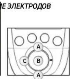
3. SELECTIONAR LA COLOCACION DE LOS ELECTRODOS

BESCHRIJVING VAN HET APPARAAT


AFSTANDSBEDIERING
BESCHRIJVING VAN HET APPARAAT

SP 6.0- EN 8.0-DOCKING-STATION
MI-action: liga (ON) ou deslga (OFF) a funcao MI-action.
PENMYUECTBA 3NEKTPOCTMUYIaIIN
3JNeKtpocTmmyIaIyraO—OueHb 3ΦΦeKTHBHy MeToD 3aCTaBnTbMbIuIb pa6oTaTb:
- CO 3HaHTeNbHbIM UJyUWeHHeM pa3JIuHbIX KaueCTB MblU
- 6e3 yTomneHn cepdeuHO-cocyndcto cnTeMb nnnncxNk;
- NOBepraC yctabI IN CB3KN NIIbO rpaHnueHHo Harpy3ke. TaKIM O6pa3OM, 3NeKTPocTmUyIaIe oBeCeuBaET 60lbNIObEMMbIeueHoi pa60tbi, Yem npOn3BOhHaJeTeJIbHOCTb.
Длдддддддддддддддддддддддддддддддддддддддддддддддддддддддддддддддддддддддддддддддддддддддддддддддддддд徴псгнгнгнгнгнгнгнгнгнгнгнгнгнгнгнгнгнгнгнгнгнгнгнгнгнгнгнгнгнгнгнгнгнгнгнгнгнгнгнгнгнgngnngngngngngngngngngngngngngngngngngngngngngngngngngngngngngngngngngngngngngngngngngngngngngngngngngngngngngngngngngngngngngngngngngngngngngngngngngngngngngngngngngngngngngngngngngngngng
-peryIrpHbIMnΦn3nueckcNmUynpaxKHeHnM;
c6aHcnpoBaHHbIM 3dOpOBbIM nHTaHneM;
c6anaHcapoBaHHbIM 06pa3OM Kn3HN.
3. KAK PABOTAET TEXHOLOГЯ MI (MbIWEHQO INHTENJIKTA)?
ПРИМЕЧАНЕ. ВКЛЮЧЕНИЕ И ВБКЛЮЧЕНИЕ MI-ФУнкции BBINOJIHЯТСЕ B MEHIO Settings (HacTpoiKn)
MI-SCAN
Ipeed hauanom TpeHnpOBKn FyHKnna MI-scan 30HnpyeT Bbl6paHHyO rpynny Mbllu, ABToMaTnueckn HactpanBaCtMnyJTop Ha BO36yDnMoCTb daHHo OBlaCTN TeNa, B 3aBNCIMoCTN OT BaWei Fn3NoIOnn.
3a yHKZI npBODIT K KpaTko TcTOBOI NOCEIOBATEHOCTN B Hauane IPOrpaMMbl, BO BpemKOTopoI npBOOJrTcNIMpeHn.
B KOHcTe TecTa Heo6xOdIMMo yBeIeNHTb INHTeHCINBHOCt, YTO6bl 3aNyCTNTb IporpaMMy.
MI-TENS
Функлma MI-tens orpanuHnBaTe HxekelaTeNbIeMbIeUeHbIe CokpaIeHnB B6OJIe3HeHHbIX MeCTaX.
C kaxdbim ybeiueHem INHTehcunBHOCTN OCUyIeCTBnIeTcra f3a TeCTIpOBAHn, n npn ObhApyeHmMbIeUHOro COKpaLHeHn npbOp ABTomAtuYeCKn CHXkaet INHTehcunBHOCTb CTmUyIaUN.
3a yHKnua doctynha Toblko B nporpammax upeckoxho 3neKtpocmnyu (TENS), 3nkohnnta (Epicondylitis) n TeHHNTA (Tendinitis).
MI-RANGE
ФункцmaI-MI-range no3BolnaT bIbpaT nbIealbHbI ypoBeH nHTeHCNBHOCTn CTmUyauuIN dJIa BOCCTaHOBJENH, Maccka, KaIIJIJIrpN3aCmN IN NOCTOARHbIX MbIeUHbIX 60Je.
B haue anpogpammbi npbiop npedlaeet nojbl3oBaTeJIO yBeJIuHTb INHTecNBHOCTb Bo BpeM yBeJIuHnI INTEHCNBHOCTn npbiop aHaJIaN3IpyET OTBe Kajdo CTmUInpyeMoM MbIuZbI N OPeJeJIeT ONTMaJIbHbI yPOBEh. KaT TObKO Mblzua DOCTnraet ONIMaJIbHOrO yOBHRA CTmUJLauZn, COOTBeTCTBuOUsK kAHAL ABTOMATUeCKN CTaHOBTcR HeAKTINBbIM, 6lOKnpy DaJIbHeJWee yBeJIuHHeNIE INHTECNBHOCTN. IJI RBOCTaHOBLeHnI KOHTPOnI pOcTo Bbl6epNTe NobTopHo Tpe6yEmbIK KaHAI N yBeJIuHbTe IINI yMeHbWntE INHTECNBHOCTcTImyJLaUzNI.
MI-AUTORANGE
Функцma MI-aurorange BbIopnHЯTe JxE 3aJauN, YTO n Φункцma MI-range, Ondako denaet 3TO ABTOMATUHECKN.
Hajatne KhoNk Co CTrpeKoB BBePb H MHOOfoHyHKUHOJbHOB NaHei B Hauane nporpaMmbI NO3BOJAE Tnp60p4y ABToMaTnueckn yBeJIuHbA Tb INTeHCNBHOCTb CTmUJLcIM Do Tex nop, noka He 6yDet o6hApJxeh ONTMaJIbHbI yPoBeH. Hajatne KhoNk Co CTrpeKoB BHN3 OTMeHaeT cyHKUIO MI-autorange. 3aTe m np60p nepeKluOaETcB pUHOb Pexim, B KOtOpOM INTeHCNBHOCTb DOnJxeh peryInpoBaT noJIb30BaTeIb.
MI-ACTION
Функця MI-action no3BONЯТ НУнот ЭЛКТРОCTUMуИnpOBaHHOE cOKpaшени C nOMOь npOn3BOJbHOrO DeIcTBnA. Takoe COKpaшени RaJIЯETCS NOHOCtBu KOHTpOJIpyEmbIM, YTO OBeCNeuBaET noNHOUeHHIe TpeHINPOBKN uYdo6cTBo DЯ NOlb3OBAteIa.
B KOHc KAKdoi Ka3bI AKTHBHO rO TDbixa NylbT DnCTaHIOHHoro ynpabneHn 13daet KopoTKn CnHa. Pocne 3TOrO MoXHO HauHAtb npOn3BOhE cokpaSeHne.EcnB TeueHne onpeDeHnro BpEmeH npOn3BOhE cokpaSeHne He HauHETcR, np6Op ABToMaTNeCKn nepExoDIT B pexm nay3bl.
3TOT pexim pa60tbi DocTyneH TOnbKO dI py nporpamM C MoUhBM MblweHyBMn COKpaueHHaMI
PIMMEAHNE.Дя npabnblho npabtoI cyHKuIN MI-action Tpe6yeTc hannue XopoWx Mbiuehix noeprmbaHn BO BpemA f3bI aKTHBHO OTDbxa.EcnO Hn ABJHO Tc HeIOCTaTOH CInbHIM, np60p n3daET KOPOTKn CnHAn, a Ha KaHANX NOBJETc 3Nk + .CooTBETCTBEHNO, dIe NOLyEHn TaKIX noeprmbaHn o6raTeNbHbIM ycNoBEm ABLAEcTc XoPoWee paccna6neHne MbUc BO BpemA f3bI OTbIXa. B KOHe cKaJdoI f3bI cokpaSeHn Heo6xoDmO BepHytbcR B NOnOKeHne, KOTope ObecneuBaet MaKcMamlbHoe paccna6neHne MbUc.
B Ta6nue yka3aHo, kakne fynkun nOctynbB KaKdo np6ope.
| SP 6.0 SP 8.0 FIT | 5.0 | ||
| MI-SCAN | ✓ ✓ ✓ | ||
| MI-TENS | - | ✓ | - |
| MI-RANGE | ✓ | - | ✓ |
| MI-AUTORANGE | - | ✓ | - |
| MI-ACTION | - | ✓ | - |
4. INHCTPYKUN
CODEPXAHAHNE HABOPOB N AKCECCYAPbl
| SP 6.0 SP 8.0 / WOD FIT 5.0 | ||||||
| № NO KAT. KOЛ-BO № NO | KAT. KOЛ-BO № NO KAT. KOЛ-BO | |||||
| ПУЛБТ ДИСТАЦНОНOGО УПРавLENEМЯ | 001047 1 | 001046 / 001046CF | 1 001048 1 | |||
| MOДУЛМ | 001061 4 | 001061 / 001061CF | 4 001055 2 | |||
| ДOK-СТАЦЕМAY | 001068 1 001068 1 001073 1 | |||||
| ЗAPÄДноЕ УСТРОДСТВО | 64902X 1 64902X 1 64902X 1 | |||||
| HAБОР MAJIЕньКИХ ЗЛЕKTPOДов 5 X 5 | 42215-8 1 42215-8 1 42215 1 | |||||
| HAБОР БOLьшINX ЗЛЕKTPOДов 5 X 10, 2 SNAP | 42216-4 1 42216-4 1 42216 1 | |||||
| HAБОР БOLьшINX ЗЛЕKTPOДов 5 X 10, 1 SNAP | 42222-4 1 42222-4 1 42222-4 1 | |||||
| КРATКOE PУКOBОДСТВО ПОЛБЗOBATEЛЯ | 885625 1 885625 1 885625 1 | |||||
| ТРАHCПОТНБИ ФУТЛР | 680043 1 | 680042 / 680043 + 680042 | 1 680043 1 | |||
| ЗАшитнычExOЛ ДлЯ ПУЛБТА ДИСТАЦНОНOGО УПРавLENEМЯ | NA NA 00 1094 1 NA NA | |||||
| USB-KABELB | 601163 1 601163 1 601163 1 | |||||
| ИНСТРУКЦЯ | 4528182 1 4528182 1 4528 182 1 | |||||
IcnoIb3yIte c daHbIM npHbOp mToIbKO uHypbl, 3NeKtpoIbl, 6aTapeu, aanTepbl nHaTHnA n Akceccyapbl, peKomeHdoBaHHbIe Compex.
ONICAHNE PIPBOPA

NYbT DnCTAHUOHHOYNPABNEHNA
A-KHONKa BKNIOUeHn/BoIKIOUeHn(HaxMNTe
DNBAKIOUeHn,HAXMNTeNyDpeXNBaTe He
MeHee 2ceKHyI,NNBbIKIOUeHn)
B-4 KhoNkI Jnra BbIbopa NOTMeHbI BbIbopa KaHaHa CTmUyIaUN
C-MHOrOfoyHKUHOHaJIbHaI naHeIb(BBepx-BHN3-BLeBO-BnPaBO)ДЯ HABINaIIM B INHTepFeIeCe I yBeIInueHry/YmEnbSeHry INHTeHCIBHOCTN CTmUJLrHn Ha Bbl6paHHbIX KaHaJax
D-KHONKa NODTBepKdEHHN
E-pa3bemIg USB-ka6eIyIINIOKNoueHnK DOK-CTAHU
MOyIb
A-KHONKa BKNIOueHn/ByIKIIOueHn(HaKMnTe IINBAKIIIOueHn,HaKMnTe N UyepXnBaIte IIN BAIKIIOueHn)
3eHbCBToNOI: np60p roTOB K paOte XeHbCBToION: BblONHReTc CTmUyra
B-na3IyHAMOTKKa6eY
ОПИСАНUE ПИБОРА
DOK-CTAHUNSP6.0N8.0
A-pa3beMДЯЗAPJKNyNbTa
ДиСТанCUHONHOrOуnpaВLEпЯн
B-na3nnOTKpbTnKpblWKNDOK-CTAHUN
C-MeTOIJIIOJ3apRkMOyNei
D-pa3bem nHTAHN
DOK-CTAHUNFIT5.0
A-pa3bemn7aepnnybTa
ДиТанцИОнHOrOуnpaВЛeпЯ
B-MeToDnPa3MeUeHnMoUyne
C-MeTOIJIPOJ3aPRAKMOyNeI
D-pa3bemnITAHIN
NEPBOE PIPMEHEHNE
Pn npBOM nCnoJb3ObaHnn DaHHoro npnbopa BblnoHnTe yKa3aHHhle HnKe DeiCTBnA:
- BbIbepnTea3bIK

- BkIIOUHTe BCE moyIn, yTO6bI CBA3aTb INx C nyltom dNCTAHIOHnHO ynpabHeHra.
Iocne BkIoueHnMoUyIero paCno3HaBaHnIyIbTOM dIcTaHcNoHHOrO ynpabHeHnHa MoUyNE NOBnEETCA OTMETKa.
PocieCBaBHaBnA BExMoUyIe CnybTom OTo6paXaTcBCEOTMeKl.
PIMMEUHNE.PoueypaCBaBbAHBaBbINHReTcOHNpa3.
ФУHKUIMПИБОРА
PIMMEUHNE.3KpaHbI, NOKa3aHHBHe HNKe, DaHbI NIIuB DnA npMepa, Ho 06uN npHcun pa6oTbIOCTaetcTeM Xe, He3aBNCMO OT NCNoB3yeMoB Bam MoDeJI.
JOCTYI K MEHIO FAVOURITES (U36PAHHOE)
B MeHIO Favourites (N36paHHoe) oTo6paXaTcR nOcLHeY BbIOnHeHHa npOrpMaM. 3TO MeHIO FauVorites eNoCte BkIoUeHn np6oPa, eCN B HEM cTb XOTb OHa npOrpMaM.
A Bb60mp MeHIO Favourites (V36paHHoe)
BПоТВерждени Вьбoga
BbIOnJIeHbIe npOrpAMMbI abTOMaTnueckn nonaJIoT B MeHIO Favourites (U36paHHoe).MeHIO Favourites (U36paHHoe) moKet coepxatb do 10 nporpAM. IIO Mepe BblonHeHry HObIx npOrpAMM OHI 3aMeHraIOT cO6oI CTapIe npOrpAMMbI B CnNcKe MeHIO.
A Bb6op Tpe6yeMoH n36paHHo nporpaMMbi
BПодТьерждени Быбoga
C Bo3BpaT K npedeIyUeMy IaIy
A Bb6op Tpe6yemoro paonoloxeHn3neKtpooB
BПодтberждени Быбoga
CBo3BpT K npedeIyUeMy wary
PacnoJoxeHne 3IeKtpoOB BbIbpaetcB O BpeM rO6paxeHn nporpaMMbl. TaKxe MoXHO npocmOTpeB dpyrHe BapnaHTbl pacnoJoxeHn.
3. NOДКПИЧЕМОДУМ K ЗЛЕКТРОДAM

PpInenIte 3neKtpoDbI K KOxe. Moynb noKnIOuaeTcR K 3neKtpoDy c6Oky. HaneHbTe Moynb Ha 3neKtpoD IO UeUka.
4. BKJIIOUHTME MOJUJIIN

A Bo3bpaT K npedeIyUeMy wary
BПоТВерждени Вьбopa
Cm. pa3dien «3anyck nporpammbbl CTmynlaunu», YTO6bI HaayaTb nporpaMMy.
JOCTYK MEHIO PROGRAMMES (IPOPAMMbI)
Iopnbhe CbeHnO nporpaMmX npBBeHb Ha Be6-caineWww.compex.info
B MeHIO Programmes (N36paHHoe) oTo6paXaIOTc KaTeOpn nporpamM.
A Bb6op MeHIO Programmes (PporpaMMbl)
BNoTBepeKdEneHbB6opa
1. BbIePHTE KATEROPNUO
A Bb6op Tpe6yeMoKaterOpnn nporpaMM
BПоТВерждени Быбopa
C Bo3BpT K nppebIyUeMy wary
2. BbIbEPHTE IPOPGAMMY
A Bb6op Tpe6yemO nporpaMMbl
BПоТВерждени Вьбopa
C Bo3BpT K nppebIyUeMy wary
3. BbIePHTE PACNoIOXeHne 3JIeKTPoIOB
A Bb6op Tpe6yemoro pacnoIooKeHnE 3neKToPOOB
BNoTBePckJeHne Bb6opa
C Bo3BparK nppebidyuemy wary
4. NOДКЛЮЧИТЕ MOДУЛМ KЗLEKТРОДAM
Ipnene Tne 3neKtpoDbI K KOxe. Modynb noDknIOyaeTcK 3neKtpoDy c6Oky. HadeHbTe Moynb Ha 3neKtpoD IO UIeUka.
5.BKJIIOUHTMEMOJYNI

A Bo3BpaT K npedeIyUeMy IaY
BПоТВерждениьбoga
Cm. pazden «3anyck nporpammbi CTmmyaunu», yTo6bHaaTaB nporpaMMy.
JOCTYI K MEHIO OBJECTIVES (3ADAU)
B MeHIO Objectives (3aau) oTo6paKaIoTc 3aau, 3aRpyKeHHbIe n3 BaWeRo NnHOrO aKKayHTa (cm. pa3dien «Co3dHne IuHoro aKKayHTa»).
ПРИМЕЧАН.Мени Objectives (Задун) дocTyHNoToJbKOДЯМоDEЛN SP 8.0.
A Bb6op MeHIO Objectives (3aDaun)
BNoTBepeKdEneHbBbOpa
INHnkaTOp no3a7auey oTo6paKaet XoE ee BbInOJIHeHry. 3HaQK KOIOKOBuNka yka3bIbAeT Ha To, YTO HA CERODH 3aIIaHnPOBaHO BbInOJIHeHne 3IemehTA 3a7aHy.
AYka3bIbAeT Ha HAIyue 3aJIaHINPOBaHHOrO 3JeMeHTa 3aJaU
B OCTaBsaJcra YaCTb
C BbInonHeHHa Yactb:
-BbINIOJIHHeHHa YacTb OTo6paKaeTc3eNeHbIM CBeTOM
-HebbinolHHHaa Yacb OTo6paKaetc KpaChbui CBeTom
1.BbIbEPNTE3Aa4y
A Bb6op Tpe6yeMoI 3aauu
B PoiTBePckJeHne BbIbopa
C Bo3BpA K nppebIyUeMy wary
2.BbIbEPNTE3JIEMENTJILBbIIOJIHEHnA
A Bb60 Tpe6yemoro 3nemeHtA
BNoTBePckJeHne Bb6opa
C Bo3BpaT K npedeIyUeMy wary
3nememrnn BbIIOHHeHH MoKet 6bIt nporpaMa nn 3aHaHne. OH BbIbpaetc no ymoJauHIO, Ho nOJIb3OBaTeJIb MoKet Bbl6pTaDpyroJ 3nemeHT.
3NaUOK 0603Haayet BbINOnHeHHyI nporpaMMy IIn 3aJaHne.
3. BbIbEPHTE PACNOJIOXEHNE 3JEKTPOIOB
A Bb6op Tpe6yemoro paonoloxeHnna 3neKtpoIOB
BIOJTBepKdEneHb6opa
CBo3BpaT K npedeIyUeMy wary
PIMMEAHHE. B 60nbHnCTBe cnyaeb HeBO3MOxHO BbIpaTb pyroepacnoJoxHe 3JeKtpoOB, TAK KAK OHO HAnpMyO CBz3aHO C 3aJaey.
4. NOДКЛЮЧЕМОДУЛК 3ЛЕКТРОДАM
PpInennte 3neKtpoDbI K KOxke. Moynb noKnIouaetcR K 3neKtpoDy c6Oky. HaneHbTe moynb Ha 3neKtpoD IO ueJka.
A Bo3BpT K npedeIyUeMy wary
BПоТВерждени Вьбoga
Cm. pa3dien «3anyck nporpammbbl CTMyIaIIN», yTo6bHaayatb nporpaMMy.
IOCTYNI K MEHIO SETTINGS (HACTPOIKN)
MeHIO Settings (HAcTpoIKN) no3BOJare HAcTpaNbTa NapaMeTpbl TAKNX 3NeMeHTOB, KaK NOcBcTeKa, rPOMKocTB, y3bIK n. T. D. HeKOTOpbIe HAcTpoIKN HeOcTyHbI dJa pa3hBiX npi6opob.
A Bb6op MeHIO Settings (HaTpoiKn)
BПодтверждени Вьбoga
1. BbISEPUTE IAPAMETP
A Bb60p Tpe6yemoro npameTpTa
BПодтberждениьбoga
C Bo3BpaT K npedeIyUeMy wary
MI-action: BkIIOuaET (ON) INN BbIKIOuaET (OFF) fynKcIIIO MI-action.
ПРИМЕЧАНЕ.Описане MI-Функци CM.В раздени «3.Kak pa6otaet texhONorma MI (MbIseHOro nHTeNtneKta)?».
Cycles (Lukbl): Bknoaet (ON) nBn BbIKIOaet (OFF) fynKmio Cycles (Lnkbl).
Функця Cycles (Lнкь) npedna3nauheHa dny liodey, kOTOpbye yxe npnbblkN K 3eKtpocTmUnyu n XOTAT BbINOHNITb HeckOJIbKO UIKNoB TpeHnpOBok. EcniФункця Cycles (Lnkbl) BkIoueHa (ON), NOBJIaETcdoONHHTeBHybI 3KpaHdI ONpeDeJIeHHbIX IporpAMM (CMoUHbIMMbISeHbIMN COKpaueHnAMy), KOTOpbI no3BOJraET Bbl6paT bIKN TpeHnpOBok.
Iognka znkla ochoBbIaetc ha Harpy3ke, co3daBaem OJekTpocTmUyIaIe. KaN B cnyae obuHoi TpeHnpOBKn, Heo6xOIMHO hauatb C onpeJeIeHHo Harpz3kn, a 3aTeM yBeJIuHBaT b ee no Mepe BblOpHeHna ZIKNoB. PekomEnduyETc NaHNaTb C 1-ro znkna I nepeXODntb Ha cIeMyIuIy uPoBeHb NO er0 3aBepShen, obuHno uee3 4-6 HeJeB CTmUyIaIuN I3 paueTa 3 ceHaCBA He Meee BaxHo DoCTnHy 3HaHTeBHO INTEHCINBO BpeMa CeAHa, npexJeem nepExoDHTK OuepeHOM znkny.
Power saving (3hepro6epekehene: BKIOUaET (ON) INI BbIKIOUaET (OFF) 3hepro6epekehene.
YMeHbIaE INHTECNBHOCTb INBpMa IIOCBETKn.
Sound (3Byk): BkIIOaET (ON) mnn BbIKIOaET (OFF) 3ByK.
Contraction sound (CnHAn o cokpaueHn): BkIouaET (ON) nIi BbIKIOUaET (OFF) npedynpejkaiou nn CnHAn o HacTynpLeHn cokpaueHn.
Set time (Bb6epnte Bpema): no30BnareT yctaHOBNTB BpeMa B np6ope.
Set date (Bb6epnte daty): no3BONrEYcTaHOBNTb DaTy B npn6ope.
Pair a new module (PoiKJIouHte HObIy MoUyb): P03BOJLaET CBraTb HOBbI MOUyb C NylbTOM DInCTAHIOHHOrO ynpabHeHn.
Reset to factory settings (K Исховим Habtpokam): no3BOJЯET c6pOcNTb HAcToKN npi6opa do nCxOДньx (иЗбpaHьпnporpaMMы иЗаду удялгTCa, HabtpoIKN no yMonuHaHIO).
System info (Инфомашия о систeme): поьоглaretnpocmoTpeb cbeDEHnO npnbope.
3ANYCKIPOIPOAMMbICTMUYILIN
Ipeep 3anyckom nporpaMMb CTmMyJauuH Heo6xOJMo BKNIOHTb Moyn.

A Bo3BpaT K npedeIyUeMy Iary
B NpOITBePKeHHe BbIbOpa n3anyck nporpaMMbl
YTo6bI BKIOHTb MOyIN, HAKMITE COOTBETCTBtuOuH KHOKNy BkIOUeHn. Iocne BkIOUeHn MOyIn Ha 3KpaHe OTO6paxaetc yPOBeH bZapra ee 6aTapei. BkIOHTe BCE Heo6xOIMbIe MOyIn corNaCHO Bbl6paHHo CXeMe paCNOJooHEn 3NeKtpoDob. Iocne BkIOUeHn Tpe6yemoro KOINecBa MOyIn B npabOn qactN 3KpaHa OTO6paxaetc He0BJsA CTpeNka.
EcnBkIooheHa yHKuMa MI-scan, nporpamma NaHnaeTc C KpaTKo NocneDobTeNbHOCTN, BO BpeM KOTOpO npOBoJATcN3MepeHn. B XoJe 3TxN N3MepeHn BaXHo OCTaBaTbCn NOHOCbIO HeNoDBNXHbIM n paccla6NeHHbIM. NocLe 3aBePseHn Tecta MoXHo 3aNyCTNb nporpamMy.
AΦa3a cokpaueHn
BΦa3a pa3MnHKn
CΦa3a aKTHBHO O TdbixA
DΦa3a paccna6neHn
E KOnuYeCTBO BbIIOJIHeHHbIX COKpaUeHn/O6uee KOnuYeCTBO COKpaUeHn
F 0603HaueHne aKtNBHOI M-ФyHKUIN
6 Bcnpbibaouee coo6eHneC uHΦopMaueNe nn noDcKa3KaMn

A BbIbepeTe KaHaJIb I da paBoTb. KoIa KaHaI aKtINBeH, CBeToIOI rOpNT CnHM LBeTOM.
B Na3a
C YBeJIueHHe IINyMeHbIeHHe INHTeHCNBHOCTN CTIMyJIaUNHa BbIbpaHHbIX KaHaJAX
YBENyBTE INHTEHCNBHOCTb CTMUYJLcHnHa BbIbpaHHbIX KaHaIax.
IyoMOnuHAnIO B Hauane ceaHcA AKTINBbI BCE KaHaJIbI. YTo6bl OTMeHnTb Bbl6Op KaHaJIa, IpocTo Haxmnte COOTBeTCTByUOyU KhoNky.
B 3TOM cnuyae TOnbKO 1 KaHaJI YBnEeTCa AKTNBHyIM. NImeHeHne INHTehCNBHOCTN BblIOJIHReTCa TOJbKO Ha KaHane 1.
IinaqpaMa BcepeINHe 3KpaHa MoKET N3MeHrTbC8B 3aBcIMOCTN OT IporpaMMbl.
ПОГРAMMA COKPAUSEHIN/AKTUBHOROTДьIXA
Takne nporpammbi Bcerda HauHHaOTc C pa3bipa3MHKn. Iocne pa3bipa3MHKn BbvINHraOTc TIKNbI cokpaueHn n AKTNBHO OToBxa (KoJIyecTBO LKNOB 3aBNCIT OT nporpammbi), a nocle 3abepweHn BCEx LKNOB Hactynaet pha paccna6neHn.

AΦa3a pa3MnHKn
BΦa3aakTNBHOOTdbixA
CΦa3a paccna6neHn
DΦa3a cokpaueHnra
E Φa3a pa60tbi, KOtopa crctoNT n3 uKna cokpaueHn/AKTNBHOOTDbixA
ПОPGРAMMbIMACCAKAIBOCCTAHOBJIECHNIA
Takne nporpammbi COCTOITN ODHoI Hc oedePka TIKKa COKpaueHn/AKTNBHOOTbIXa.3To nporpammbI DnBocCTaHOBLeHn, Maccaxa, KaINIIpRn3auu N NOCTOARHbIXMbIeUHbIX60Je.B XoJe TAKNX nporpamM MoKET N3MeHrTbcraCtOta CTmUJLauu.
AΦa3a pa6oTbi
ПОДOLЖЕНЕ ПОГРAMMbI CTМУЛЯЦИ

B03BpaT K
B Bo3o6HOBHeHc eHaHc CTmUyIaun
C Pnponyck Tekyu
nporpaMM
NIN BbIXOДИ3
A CpeHnIHHTeHCNBHOCTB CTmUyIaUN
B MaKcImaJIbHaI INHTeHCINBHOCTb
CTIMMYLILM
Ipn Haxatn Ha ceHTpaBHyIO KONky Ha npIbTe DnCTaHIOHO ynpaBHeNna HA KNOKy BkIoueHn OndHO r n3 MoIyNe BO Bpemr CTmUyIu nn pnp6op nepexoNT B pexm nay3bl. Ha 3tOM 3Tane MOxH npOnyCTnTB TeKuIyO f3y nIe BbiTN I3 npOrpaMMbl.
B 3aBnCIMOCIn OT npoPamMbI MoKET OTo6paXaTbcra MaKcImaJIbHoe IIN CpeJHee 3HaueHne INHTECNBHOCTN.
ПИМЕЧАН.Сааньб036новлгетсяHaурбHe 80% ot урбн ИHTEHCBHOCtДопиpepbIbA.
CBeToIOI MraE: BbInOnHReTc3apKaMoyn
PIMMEAHHE. Ecn np6op He nCnoB3yeTcnpoJnxTeIbHoe BpeM, Mbl peKOMeHnyem 3apxKaTb 6aTapeNdo ypoBn 50% kaxdbie 3 Meca.
Korda moynb nomeetaetcB DOK-CTAHIO, OH OTO6paXaETcRa H ekpaHne nyIbTa DnCTAHIOHO ynpabHeH. Iocne noHno 3apAkn yIbTa DnCTAHIOHO ynpabHeHn MOyJeOHN nepexOJrB pexm OxndaHn.
KordaMoynb NomeaetcB DOK-CTAHUHO, 3eHbI CBToNDIOJ NOKa3bIBaET erO COCTOHNHe. Pocne noHnO3apdKn NylbTa IACtAHuOHHO ynpabNeHnN MoynE OHN nepeXoJAT B peKIM OxndaHn.
C03DAHNEJIIMHOROAKKAYHTA
UTo6bI BOCnObl30BaTbcra BcEMN BO3MOXHOCTrMn Pn6bopa, Co3daIte aKKayHT Ha Be6-caTe WwW. compexwireless.com n cneyuTe INHCTpyKuYMa H a TOM Be6-caTe.
Функции модел SP 8.0
ДостункpacnicaHIOТренpoBOK
CkaaHbAHne npedyctahOBHeHHbIX 3aDaHnpaMyoB np60p
·Co3dHHe co6cTBeHHbIX cIeNe INX cKaUBaHHe B npBop
- 3arpyuka nctopn npnbopa (BbinoHHeHHbIX nporpaMM CTmMynaq) Ha Be6-caNT
Iocne ckaibnna 3aauh na npbl TnctaHIOHHO ynpabHe n BkloyeHH npbopa Ha 3kpahe cpa3y OTo6paxaetc 3KpaH C exeJHeBbIMn 3aHaHnMn.
Функшн Mоделу SP 6.0 u FIT 5.0
Достун К распсанMu TpeHpoBOK
- 3arpyka nctopn np60pa (BbinoHHeHHbIX nporpamm CTmmyraun) Ha Be6-caNT
5. ПОИСК И YYSTPAHEHNE HENCPPABHOCTEД
OTKA3 3JIKTPOДA

Ha npIbTe DnCTaHcHOnHOrO ynpabHeHnOTo6paKaetCnBON 3neKtpoJa NOTKJIoueHHOrO MoyJra, a TAKKe Miraet CTrpeNka, yKa3bBaHouaJHa COOTBeTCTByUoJn KaHAn (B DaHHOM clyuea KaHAn 1).
- Y6eHITcB, yTO 3NeKTPoDbI npaBnIbHO IOKnIIOueHbI K MoDyIIO.
- Ecnn 3neKtpoDbI CTapbIe, n3HOWeHHbIe n/nn HApyWeH KOtAaT - nonpO6yIte 3aMeHHTb 3JKeKTPoDbI.
MOyIb BHE 30HbI DEICTBnA
Ha nylte dntaHOnHO ro npabHeNra OTo6paKaetc CmBOJ MOyIa BHe 30hJI deICTBna, a TAKKe Mnrae cTpeNka, yka3bIbaIOUa Ha COOTBeTCTByIOu KaHAn (B daHHOM cnYae kaHAn 1).
Y6eHntecb B Tom, yTo MoyIb I nyIbT DnCTaHcNHO HnpabNeHna HaxOJaTcHa paccToHHm MeHee 2 MeTpOB dpyr OT dpyra.
Mexdy Modyne m nybrom dctahnoHHoro ynpabnene He dojxho 6bIb npenrTcbn, kotopbe moryt OTPaKATb CnHan.
YbEInTeB TOM, YTO CINHAn DoCTnHaet NylTa INCTaHIOHHOr O npabneHna.
ПОНБЛЕМССИХРОИЗАЦЕI

Ecn npoeypa cnHxpoHn3aun 6bIa npepbHa nn He moKet 6bItb ycneuHO BblnoHeHa no KaKMnlo6 npuHHAM (OTcoeHNHe NylbT DnCTaHcNooHoro ynpabNeHn, OTCyTCTByET NtAHne n T.Д), Ha nyIbTe dntaHcNooHoro ynpabNeHn OTo6paxaetc cJeDyOuM ekpaH.
- PoioknIOHTe NOBTOPO HnybT DnCTaHcNOHHOrO ynpabNeHnK KOMNbIoTepy npe3anyctnte npoedypy CnHXPOHn3aUIN.
CBETOIOIOHbIE INHINKATOPbI MOyJIA
HnIkaTOp nonepeMeHHO 3aRopaETc 3eHebIM KpaCHbIM cBeTom: MOnyIb HaxoNTcB He 30HbI DeiCTBn IIN He paCnO3Haetc NylbTOM INCTaHIOOHHO ynpabJeHn.
- Y6eDNTecb B TOM, UTO NylbT DnCTaHcNHOHOrO ynpabHeHBAKJIIOueH.
- Y6eIntecb B TOM,чTo MOnyIb I nyIbT nIcTaHcHOnHOrO ynpaBneHnHa pacCToHn MeHee 2 METPOB dpyr OT dpyra.
INHdkaTOp ropnt KpaChbIM UBeTOM.
- Y6eNTecb B TOM, yTO MOyIb 3apJxH.
-Nonpo6yIte nepe3anyctnb nybT dntaHcnoHHoro ynpabJeHn I ModyuN. - Eсииндикаторnpoiodлжаet ropetb kpaCHbIM cBeTom,obpaTHTecbВcnyk6by noДeprKKN KOMnHIN Compex.
HnDnKaTOp He roPnt.
- Y6eJntecb B TOM, YTO MOyIb 3apJxHe.
- Ecnn HnDnKaTOp He 3aRopaTa, o6paTnteCb B cnyk6y noDnepKKn KOMNaHm Compex.
MOДУЛБ PA3РЯЖЕH

Bo Bpemr CTmmyaun MOnyIb MoKet pa3prnTbcB. B 3OM clyuae OTo6paKaetaC TcMbON pa3prKeHHoB 6atapen, a Takke mraet cTpeNka, yka3bibaOuHa COOTBeTCTByIOUaN KaHAN (B daHHOM clyuae kaHAN 1).
- OctaHOBInTe CTINMUYLJIIO INpe3apJrIte MOyIb.
- OctabBe Ta3pJxKeHHb MoDyIb N npOdoJIkaTe CeAHC CTmUyIaIcN 6e3 HrO.
MOyJIbHE CBA3bIBAETC C NylbTOM DnCTAHIOHHOYYPABJIENIA
EcnB Bo Bpem npBOrno nCnOb3OBaHnnyIbTy DnCTaHcNHOHorO ynpabHe He ydaetc CBA3aTbcra Co BCEMMOyJMy, NOBJeTcCo06eHne 6 oOn6ke.
YBeHNTecbBTOM,HTOMOyIb3apJxKeH,NIOBTOPITpeIPOeDpyCBA3bBAHNIA.
- Ecni coo6eHne oTo6paxaetc CHOBa, o6paTntecb Cnyx6y noDnepxxK KOMnaHm Compex.
CTMUYIaIyHE DaET ObIyHbIX OUyEHH
- Y6eHntTeCb B npaBnIbHocTn HacTpOeK n pacNoIoxKeHn 3JekTpOoB.
- UyTb cDvHbTe 3neKtpoDbI.
CTMUYIaIyBbI3bIBAETDICKOMΦOPT
3ΦΦeKTHBnH MaOuHocb N3nyeHn:4.4 [D5M]
CTAHДAPTBI
Дя obecneuehenia 6e3onacnoctn nCNoIb3OBAHnA CTmUyIaTOp cKOHCTpyuropoBaH, npOn3BeDeH npacnpoctpaHareTcB COOTBeTcTBn C Tpe6OBAHnMn DnpeKTnBbI EC 93/42/CEE c nonpaBkAmn, OXBtBIAIOUe MeDnUHckne npi6opbl.
CTMnyIaTOp TAKKe OTBeuAeT CTAnDapTy CEI 60601-1 no 6UIM Tpe6oBaHnAm K 6e3OanAcHcTn MediunHcknx 3JIeKtpopnp6obop, CTAnDapTy CEI 60601-1-2 no 3JIeKtpomarHnTHoN COBMeCTmocTn n CTAnDapTy CEI 60601- 2-10 no CneuaJIbHbIM Tpe6oBaHnAm K 6e3OanAcHcTn HEPBbIX N MbIeUHbIX CTMnyIaTOpOB.
B COOTBETCTBnC DeIcTBUOUMM MeXdyHapoDhIMn CTaHdApTAMN CneJeYt npEynpeINb o6 yctAHOBKe 3NeKTPoDnBa H rpydHyIO KNeTKy (NoBbIeHHbI pNCK fIbprnnnaCePda).
Даньий CTимулгетор Тадже OTbeчael TИpeктпe 2002/96/CEE no ytNiIN3aUNI NJIeKtpnueckoro n 3JIeKtpoHnOro obOpudobAHry (WEEE).
CBEDEHINOB3JEKTPOMAHHTHOJ COBMECTIMOCTN(3MC)
CTMnyIaTOp Compex npedHa3HaueH dJa IcNoIb3ObaHnB TnIuHbIX DoMaUHIX ycIOBnIX n ceptnФицрOBaH B COOTBeTCTBnN CO CTaHdApTOM 6e3oNaChocTn EC 60601-1-2 (3JIeKtpomarHHTha coBmecTImOCTb).
JaHHbI npH6Op n3nyaET KpaHHe Hn3Km yPoBeHb paJIOuacToTHbIX (Pc) nomex nBpR nn OKaKeT BnHnE Ha paCnoJIoKeHHoe NO6n3OCTn 3JeKtpoHHoe o6OpydoBaHne (paJIO, KOmNbKTepebl, TelefoHbI nT. n.).
KoHCTpykunr cTmmylraTopa Compex npeducmaPnBaet ero 3auNTy ot npedckayeMbix nomex,NCXODaIUXOT 3JeKTPnuecknx pa3pRIOB, MaHHTbIX nOJIe, a TaKke NCTOCHIKOB NITaHNIpaDIOuCACTOTbIX CnHAIOB.
OHaKO HeB03MOxHOrapaHTnPoBaTb,TO Ha CTmUyIaTOp He 6ydyT Bo3JeCTBOBaTcINbHbIe Pu (paIOuactOThIe) noJIa, BO3NkaIOuIe INbIM O6pa3OM.
3a noipobnbIMn cBepeHnmaMn 06 3JIeKtpomarHHTbIX n3IyueHnX n Iomexo3aunuHooCTn o6paauTecb B Compex.
8. TABLIUNA 3JIeKTPOMAHHTHOI COBmECTMOCTN
CTMnyIaTOp Compex Tpe6ye TcneuaNbHbIX Mep npedocToPOXHOCTN B OTHoWeHN 3MC. Ero yctaHOBka N BBOD B 3KcnPyatauIO DoJxHbIO CcyueCTBjAeB C COOTBeTCTBN C daHHbIMy, yka3aHHbIMN B Ta6nue 3MC HactOraJe rpykoBoDCTBa.
Ha pa6oTy CTmUyIaTopa Compex mOryT oka3bIbTaB BInnaHne IIO6bIe 6ecnpoBOIhble nepedaIooJIpe PUY-Prn6Opbl. IcnoIb3OBaHne npHaJdIeXHOCTe, daTchNKOB IN Ka6eJIe, OTnUHybIX OT yKa3aHHbIX pOnI3BOIHTeMe nPn6Opa, MOryT pNpIBeCTn K ycINJeHIO nomex IIIN CHNXEHIu UcToHNUBOCTn CTmUyIaTopa Compex K nomExaM.
CTMnyIaTOp Compex He cIeJyET nCnoJIb3OBA Tb B6n3n dpYrOro 6OBpyoDaHnra. EcIn Tpe6yeTc nCnoJIb3OBA Tb erO B TaKnx ycNoBnX, npOBepbTe npaBnIbHyIO pa6Ot y CTMnyIaTopa Compex B daHHoN KOhNrgpaunn.
| PEKOMHDAUZNI 3A8BILENHE IPOIN3BOJNTIEL OTHOCHTELBHO 3LEKTPOMAHINTHO 03LNUEHNIA | ||
| MioocTimyJATop Compex Stimulator npednauChen dans myonb3OBAHnB B 3lektpomarHHTno cpeDe, onpdeIeHHo HIXe. 3aKa3uK nII pIoB3OBaTeJIb MIOCTIMyJATopc Compex Stimulator dOnJxH y6eIHbCS,чTO uCTPoiCTBO nCNoJIb3UeTcB TAKO CpeDe. | ||
| ПROBEPKA 03LNUEHN COOTBTCTBVE | 3LEKTPOMAHHTHAR CPEDA - YKA3AHNIA | |
| PCHIaYHeNe CISPR 11 | Гулла 1 | В мioocTimyJATope Compex Stimulator padnoachToTHa Зергяи IncpoJIb3UeTcR ТольКо ДЛ BHyTpEnHero ФункциOnHApOBaHn. ПОТOMу МAnOBepoTnO,чTO PCHIaYHeNe UcTPOiCTBa ВыIZOBet ПOMEXI B pa6Ote СоeDInx 3leKTPuYeCKNX uCTPoiCTB (Ради, KOMlbIOTepbI,ТeLefOHNbI N.T.D.). |
| PCHIaYHeNe CISPR 11 | Клacc B | MioocTimyJATop Compex Stimulator moXHo ИсрпьзOBaTb B LIObOM Учрждени,если 3TO He ЧASTHoe JxINBe I Ne MeCTO, СнabЖaEMOE 3LEKTPO3HeprNié НаprMyO OT CSIT NHI3KOTO НаprжЕнЯ, KOTOPa R PHTaET ЖИltbIe Doma. |
| ГарmonuYeCKne 03LNUeHry IEC 61000-3-2 | Клacc A | |
| КолБанЯ habражЕнY/ КолБанЯ 03LNUeHry IEC 61000-3-3 | He npimehIMO | |
| PEKOMHDAZUNI IN 3AABVLEHNE IPOIN3BODHTELA OTHOCNTELBO 3JEAKTPOMAHHTHOYCTOUYBOCTN | |||
| Мностимулгор Compex Stimulator predecessor INДЯСпОЛБЗВОВАЙ B AZEКТРOMAHHTHONСpeDE, onpeDEJIENHOn ніж. Покуател.IИ ПOKьЗВОВАЙ МИСТIMУЛТOPA Compex Stimulator obryan ybeDITbCS,чTO uCTPOMCTBO ИСПОЛБЗУETСВЕРКOMHDDOBANHONСpeDE. | |||
| ПЮВЕРКHA H3AUHTY OT ИЗЛУЧЕНЯ | ΥΡОВЕHB ПЮВЕРК IEC 60601 | ΥΡОВЕHB COOTBETCTBIV | 3JEAKTPOMAHHTHAR CPEDA - PEKOMHDAZUNI |
| З_LEКТROСТАПUCEСКИ разрд (ESD) CEI 61000-4-2 | ±6 KB priп контakte ±8 KB в ВОДУХ | ±6 KB priп Кontakte ±8 KB в ВОДУХ | ПОЛ дOLЖны 6ытБ DepeВЕHнБIM, КаменьIM ИПОКрВITIM Керампеско рПИТКО. Еспли пОЛпКрВIT сИнТеПUCEКIM MATERIANOM, OTHOCNTIELHЯ Влajхость ДОЛЖна COCTABNATь He MeHee 30%. |
| НанOSEКУнDIБLE ИМПУЛСНБLE ПOMEXI CEI 61000-4-4 | ±2 KB Дд LAIIHIN ПОДАЧ ПИТАHЯ ±1 KB Дд LAIIHIN ВВODA/BvIBODA | ±2 KB Дд LAIIHIN ПОДАЧ ПИТАHЯ | КачесТВ сETY AZEКТРОСАБЖЕHЯ ДOLЖNo COOTBETCTBOВАБ STAnДAPТУ Дд KOMМЕЧESKO ИПIM MediunHCKOTO UyPexДЕHЯ. |
| МИКROSЕКУнDIБLE ИМПУЛСНБLE ПOMEXI CEI 61000-4-5 | ±1 KB в ДИФ�ерEHДALHOM рекIMe N/A | ±1 KB в ДИФ�ерEHДALHOM рекIMe N/A | КачесТВ сETY AZEКТРОСАБЖЕHЯ ДOLЖNo COOTBETCTBOВАБ STAnДAPТУ Дд KOMМЕCHESKO ИПIM MediunHCKOTO UyPexДЕHЯ. ПИIM MediunHCKOTO UyPexДЕHЯ. |
| Пювалы наразоженя, КраТКOBРЕмENHьс cбОи I Колебань наразоженя На ЛINи ПОДАч ЗLEKТРОЗHERPGN CEI 61000-4-11 | <5% VT (npoВалы >95% UT) дд 0,5uzKlna <40% VT (npoВалы >60% UT) дд 5uzKlnob <70% VT (npoВалы >30% UT) дд 25uzKlnob <5% VT (npoВалы >95% UT) дд 5cekYNd | <5% VT (npoВалы >95% UT) дд 0,5uzKlna <40% VT (npoВалы >60% UT) дд 5uzKlnob <70% VT (npoВалы >30% UT) дд 25uzKlnob <5% VT (npoВалы >95% UT) дд.5cekYNd | КачесТВ сETY AZEКТРОСАБЖЕHЯ ДOLЖNo COOTBETCTBOВАБ STAnДAPТУ Дд KOMМЕCHESKO ИПIM MediunHCKOTO UyPexДЕHЯ. ПИIM MediunHCKOTO UyPexДЕHЯ. |
| МагинTHOE NOLE c ЧASTOTМПТAOОSE сети (50/60 Г) CEI 61000-4-8 | 3 A/m 3 A/m | ΥΡОВЕь МагинTHOE NOLE nромышелен�учAstOTbl ДOLЖEN 6ытБхapakTepньIM Дд ТИПИнHOrO MeCTa PaCnOLOXeHЯ СТAnДAPТHORO KOMМЕCHESKO IПIM МEDIINHCKOTO UyPexДЕHЯ. | |
| Примechanical.VT predstablaet сбов наразоженie nepeMuJENHOrTo TOKaВ сети до поprimenuHЯ уразьня поразьки. | |||
| PEKOMEHNDAUHIN 3AABVLEHNE IPOUN3BODIHTEJI OTHOCNTEJbHO 3JIeKTPOMAHHTHO YCTOUYBOCTN | ||||
| MioctimyraTOp Compex Stimulator prendaHa3nueHEn dIa MIOcno3bOVAHn B 3JIeKTPOMAHHTHO cpeDe, onpeDeJeHnHO Hnke. PloKunatel ny nolb3oBaTeB MIOCTIMyraTopa Compex Stimulator o6a3an y6eDntbCBy, ChTo uCTpoiCTBO ncnolb3yeTcB PekomehdobAHNO CpeDe- PEKOMEHDAUHIN | ||||
| PPOBEPKA HA 3AUHTY OT n3LNUHENIA | YPOBEHb PPOBEPKI IEC 60601 | YPOBEHb COOTBETCTBNI | 3JIeKTPOMAHHTHA CPEDA - PEKOMEHDAUHIN | |
| Ppovodimai radinoactota IEC 61000-4-6 n3nyaeMa radinoactota IEC 61000-4-3 | 3 B cpeNdHeKBaDp. ot 150 KfUdo 80 MfU 3 B/M ot 80 MfUdo 2,5 ITU | 3 B cpeNdHeKBaDp. 3 B/m | PepenocHbIe N moBILhBie PCH-ycTroRcTBa DnIe C7BzIe MOxHIO NcNoJIb3OBAbT pIADOM C MIOCTIMyraTOpOM Compex Stimulator ero npovodami TOnbko Ha pacCToHmN He 6blXe peKoMeHdOBaHNO r paccHTaHNO C NMOUbIc COOTBETCTBHyUOe UpaBHeHn DnIe qACTOT nepeDaTchka. PeKoMeHDoBAnHoe paCCSTOHe d = 1,2 √P d = 1,2 √P ot 80 MfUdo 800 MfUd d = 2,3 √P ot 800 MfUdo 2,5 ITU rDe P npedCTabJIeT MAKCImaJIbHyo HOMInaJIbHyo BbIXOHDHyo MOUHCTB pepeDaTchka B BAITax (BT), 3aDaHNo TY TeHXuHeCKIMs XapakTEPICTNkAMn npou3BDoHtEnA, a-d - peKoMeHDoBAnHoe paCCSTOHe B MeTpax (M). HapRAJHNOCTb NpOI O T fIKCpOBaHbIX padiuOaCToTHbIX pereDaTchNKOB, kAc ONpeDeJIeHO B IVCCLeDobAHN 3JIeKTPOMaHHTbIX 30H a,doJXHnA 6bITb Nne HUe UPOBNA COOTBETCTBRI B KAKDOM dIaIaIaONe ChactoTbIb. Pn HAIuHnPi No6bIaOCTn Prin6oBv, OTmeuHbIX cIeDuOUsIM CIMBOLOM, MOrTy Bo3HnKHyTb NOMEXH. ((@)) | |
| PpIMeAHHE 1. Ppi 3NaueHn8x 80 MfU and 800 MfU pRimeHReTCE 6oJIee BeBicKm JuaCTOThb.IduaIa3OH. PpIMeAHHE 2. DaHhBle peKoMeHdaUHm MOrgT IOXoDHT He dIg BceC SiTuaUcn. Ha paCpOcTpaHHe 3JIeKTPOMaHHTbIX BOIH BnIaHOT NpGLoSeHne I OPAxBeHne OT KOHCTpyKlum, obBeKTOB IuOJe. | ||||
| a HApRjExHHocTb PoneJ ot TaKnx φIckCpOBaHbIX NpeedeTChKOB, kac 6a3OBbIe CTaHUn DnIe radIoTeneΦoHOB (cOTobix/6eBcnpoBDOHbIX) i Na3eMHbIe padIOCTaHUn, li6bIteLckSNe PADIpepeDAtChK, radIOBeUeHnne AM i FM, a TAKKe TEleBeUaHHe, HeBZMoKHo ppeDcKa3aTb ToCHo. PtoTOMU MoKet Bo3HnKHyTb HeobXoDMocTb B npOBeHdHn aHAlIa3a 3JIeKTPOMaHHTHcI CreDe b HObEkeT daPacYe Ta NapAmetPoB 3JIeKTPOMaHHTHcI CreDe, foPmriPyemoi fIKCpOBaHbIMN PCH-pePeDAtChkAMn. Ecln HApRjExHHocTb PoneJ, n3MepeHnRa B cpeDe, rde paCpIoJoxeH MIOCTIMyraTOp Compex Stimulator, npebbIaer donyuctmbu yOBoVeB PCH-coOTBETCTBRI, yka3aHbN BviIe, to cIeDuET NaIpaTb 3a MIOCTIMyraTopom Compex Stimulator i y6eDntbC B erO hNDeJaAseФyHKUOnHropOBAHn. B clyuHae He npabInbHn pa6ObTIb MoXHn prinHbT cooTbETCTBuOuIe MeBy, HapImep, n3MeHntb opineTaIIO B npocTpaHCTBe MIOCTIMyraTopa Compex Stimulator iI nipeMeCTnB erO. b DnlauchToTHo DnIaIa3OHa ot 150 KfU do 80 MfU napRjExHHocTb PoneJdoXHn 6bItb <3B/M. | ||||
| PEKOMENIOBAHNOE PACCTOJHNE MEXDAY PEPEHOCHbIM IN MOBILHBIM OBOPYODOAHHEM DIA CBZ3N IN MNOCTUMUYJATOPOM Compex Stimulator | |||
| Mnoctumyjatop Compex Stimulator npedha3nueh dIra nCpOJIb3OBaHnB B 3JIeKTPOMarHHTHO CpeDe c KoHTPOMIPUeMbIM N3JIuHaembIM paDIOuACTOTNbIM BOJHAM. POKyNaTeB IINI pOJIb3OBaTeB Compex Stimulator moKet noMooy npedotBparNTb BO3NIKHOBEHne 3JIeKTPOMarHHTbIX NOMEx, oBeCpeuB NoIepXaHHe MInHMaJIbHO rO pAcCTOJHNA MEXdy pePeHOCHbIM N MOBILbIMn PAIOuCACTOTNbIM cpeCTBaMn CBZ3N (pepeDaTHKAMN) IN MNOCTUMyJATOpom Compex Stimulator, kA peKOMEnDOBaHO B Tablue HIXe, B COOTBETCTBN C MaKcImaJIbHO BvIXODHO MOUHOCTBIO CpeCTB CBZ3N. | |||
| MAKCSMALNBAA BvIXODHA MOUHOCTB PEPEDATUKA, BT | PACCTOJHNE B COOTBETCTBN C CHACTOTOH PEPEDATUKA, M | ||
| OT 150 KfU DO 80 MfU D = 1,2 √P | OT 80 KfU DO 800 MfU D = 1,2 √P | OT 800 MfU DO 2,5 fU D = 2,3 √P | |
| 0,01 0,12 0,12 0,23 | |||
| 0,10,38 0,38 0,73 | |||
| 11,2 1,2 2,3 | |||
| 10 3,8 3,8 7,3 | |||
| 100 12 | 12 | 23 | |
| ДЯ nepeDAtHuKOB, MAKcIMaJIbHAA BvIXODH YA MOUHOCTB KOITbIX He uKa3aHa B TabeLuce BvIIe, peKOMeHNDbAHHOE pACCTOJHNe d B MeTpax (M) MOnHOb OUnHbT C pOMOUsbФOpMunb, UChITbIBAOUeH chactOtU nepeDAtHuK, rDe P - MAKcIMaJIbHAA BvIXODH YA MOUHOCTB pepeDAtHuK B BAITax (Bt) corIacHo daHbIM npOIN3BOUHTEH PpeDAtHuK. ПРIMEUYAHNE 1. ПуЗнчЕнгх 80 MfU and 800 MfU primeHЯETcR paCCSTOJHne dlya 60JIee BvICOKO rO cAChTOrHr DiuapAn3OHa. ПРIMEUYAHNE 2. Дадье peKOMeHNDAzHm MOgUT NOxOxDITb He dlya BcEx SiTuAzuH. Na pacnpoCTpanHene ЗлeKTPOMaRIHbTHbIX BOLN BvIaHOT pOgLoUeHne i OTrApKeHne OT KOHCTpyKuzH, obSeKToB nIoude. | |||
Fit5.0
SP6.0
SP8.0
BRUKSANVISNING
INNEHÄLLSFORTECKNING
FÖRDELAR MED ELEKTROSTIMULERING
DET GÄR INTE ATT PARA MODulen MED STIMULATORN