GTB 12V11 Professional - Screwdriver BOSCH - Free user manual and instructions
Find the device manual for free GTB 12V11 Professional BOSCH in PDF.
User questions about GTB 12V11 Professional BOSCH
0 question about this device. Answer the ones you know or ask your own.
Ask a new question about this device
Download the instructions for your Screwdriver in PDF format for free! Find your manual GTB 12V11 Professional - BOSCH and take your electronic device back in hand. On this page are published all the documents necessary for the use of your device. GTB 12V11 Professional by BOSCH.
USER MANUAL GTB 12V11 Professional BOSCH
natural_image
Two Bosch 3D-printed portable flash units with black end caps and orange handles, displayed against a plain background (no text or symbols visible on the devices themselves)Robert Bosch Power Tools GmbH
70538 Stuttgart
GERMANY
www.bosch-pt.com
1609 92A 4RE (2018.10) T/73

1 609 92A 4RE
GHG Professional
HEAVY
DUTY
20-63|23-66

BOSCH
en Original instructions
fr Notice originale
pt Manual original
es Manual original
pt Manual de instruções original
zh 正本使用说明书
zh 原始使用說明書
th หนังสิ่อคุณิอาการใช้งานฉบับ ต้นแบบ
id Petunjuk-Petunjuk untuk Penggun aan Orisinal
vi Bàn gốc hướng dẫn sử dụng
ar دليل التشفيل الأصلى
fa دفترچه راسنمای اصلی
English ...... Page 6
Français ...... Page 13
text_image
BOSCH Professional MAX (1) (2) (3) (4) (3)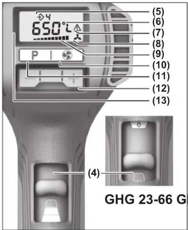
text_image
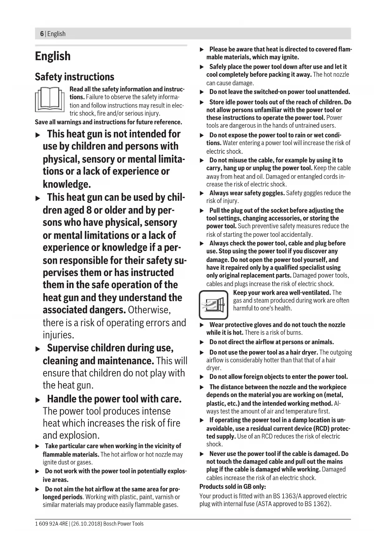
650°C (5) (6) (7) (8) (9) (10) (11) (12) (13) (4) GHG 23-66 G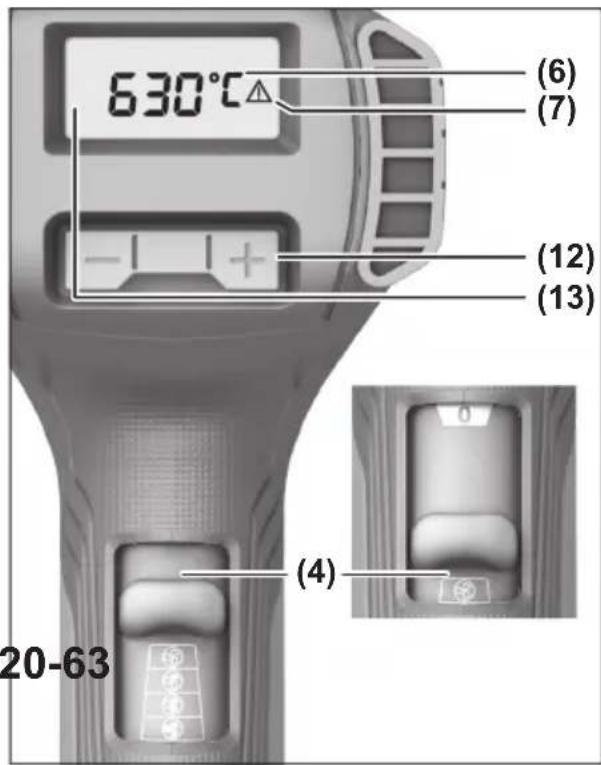
text_image
630°C (6) (7) (12) (13) (4) 20-63A
natural_image
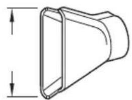
Technical line drawing of a conical mechanical part with two downward arrows indicating depth (no text or symbols)75 mm 1 609 390 451
50 mm 1 609 201 795
text_image
BOSCH (14)B
natural_image
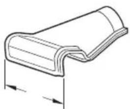
Technical line drawing of a mechanical component with two vertical arrows indicating measurement or dimension (no text or symbols)75 mm 1 609 390 452
50 mm 1 609 201 796
text_image
(15)C
natural_image
Technical line drawing of a U-shaped mechanical component with dimension arrows (no text or symbols)80 mm 1 609 201 751

text_image
H₂O (16) BOSCH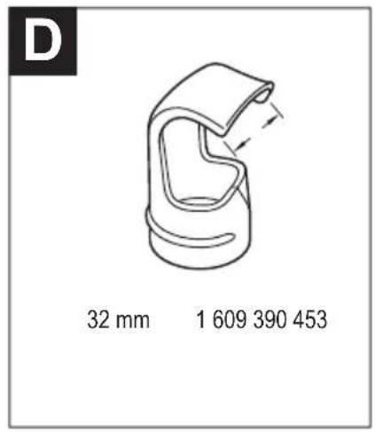
text_image
D 32 mm 1 609 390 453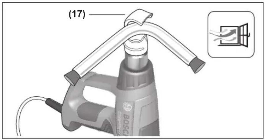
text_image
(17) BOSC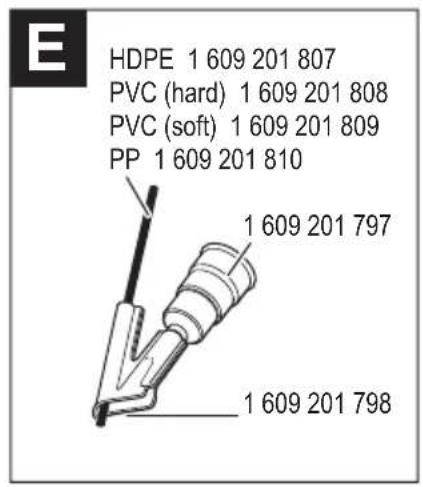
text_image
E HDPE 1 609 201 807 PVC (hard) 1 609 201 808 PVC (soft) 1 609 201 809 PP 1 609 201 810 1 609 201 797 1 609 201 798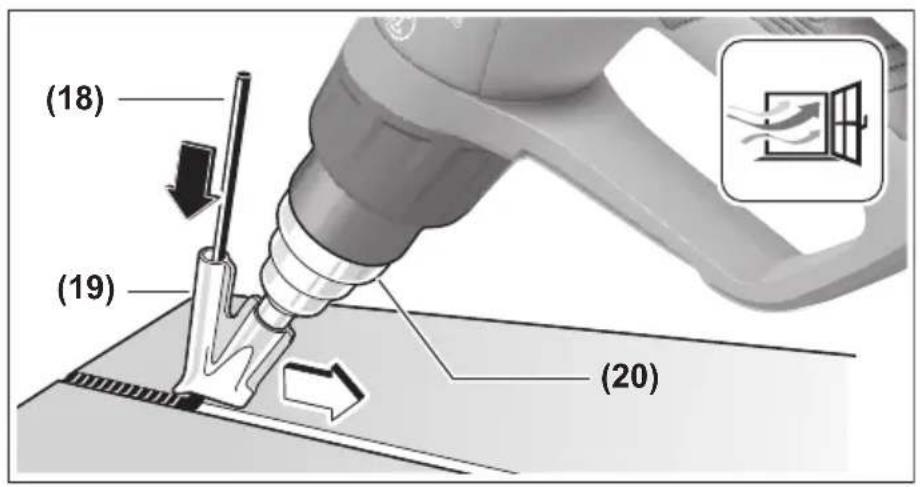
text_image
(18) (19) (20)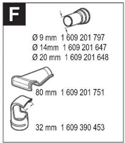
text_image
F Ø 9 mm 1 609 201 797 Ø 14mm 1 609 201 647 Ø 20 mm 1 609 201 648 80 mm 1 609 201 751 32 mm 1 609 390 453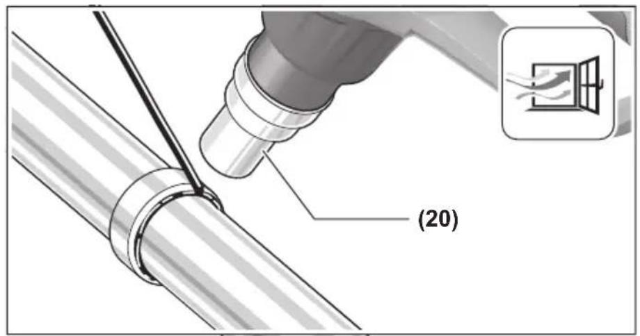
text_image
(20)
text_image
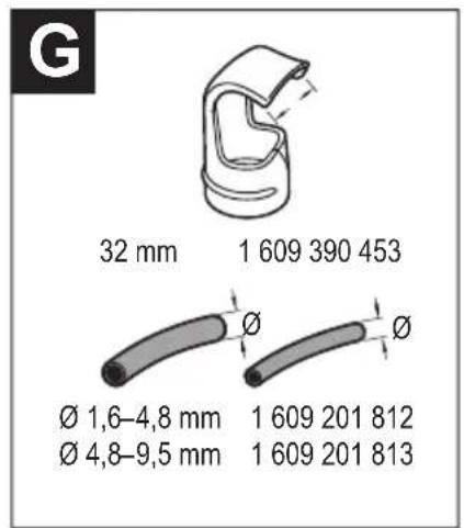
G 32 mm 1 609 390 453 Ø 1,6-4,8 mm 1 609 201 812 Ø 4,8-9,5 mm 1 609 201 813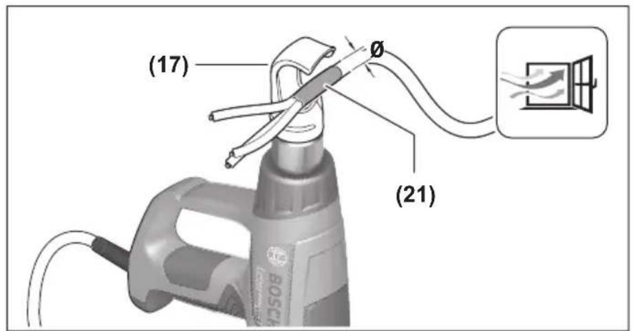
text_image
(17) (21)English
Safety instructions

Read all the safety information and instructions. Failure to observe the safety information and follow instructions may result in electric shock, fire and/or serious injury.
Save all warnings and instructions for future reference.
This heat gun is not intended for use by children and persons with physical, sensory or mental limitations or a lack of experience or knowledge.
This heat gun can be used by children aged 8 or older and by persons who have physical, sensory or mental limitations or a lack of experience or knowledge if a person responsible for their safety supervises them or has instructed them in the safe operation of the heat gun and they understand the associated dangers. Otherwise, there is a risk of operating errors and injuries.
▶ Supervise children during use, cleaning and maintenance. This will ensure that children do not play with the heat gun.
▶ Handle the power tool with care. The power tool produces intense heat which increases the risk of fire and explosion.
▶ Take particular care when working in the vicinity of flammable materials. The hot airflow or hot nozzle may ignite dust or gases.
▶ Do not work with the power tool in potentially explosive areas.
▶ Do not aim the hot airflow at the same area for prolonged periods. Working with plastic, paint, varnish or similar materials may produce easily flammable gases.
▶ Please be aware that heat is directed to covered flammable materials, which may ignite.
▶ Safely place the power tool down after use and let it cool completely before packing it away. The hot nozzle can cause damage.
▶ Do not leave the switched-on power tool unattended.
▶ Store idle power tools out of the reach of children. Do not allow persons unfamiliar with the power tool or these instructions to operate the power tool. Power tools are dangerous in the hands of untrained users.
▶ Do not expose the power tool to rain or wet conditions. Water entering a power tool will increase the risk of electric shock.
▶ Do not misuse the cable, for example by using it to carry, hang up or unplug the power tool. Keep the cable away from heat and oil. Damaged or entangled cords increase the risk of electric shock.
▶ Always wear safety goggles. Safety goggles reduce the risk of injury.
▶ Pull the plug out of the socket before adjusting the tool settings, changing accessories, or storing the power tool. Such preventive safety measures reduce the risk of starting the power tool accidentally.
▶ Always check the power tool, cable and plug before use. Stop using the power tool if you discover any damage. Do not open the power tool yourself, and have it repaired only by a qualified specialist using only original replacement parts. Damaged power tools, cables and plugs increase the risk of electric shock.
Keep your work area well-ventilated. The gas and steam produced during work are often harmful to one's health.
▶ Wear protective gloves and do not touch the nozzle while it is hot. There is a risk of burns.
▶ Do not direct the airflow at persons or animals.
▶ Do not use the power tool as a hair dryer. The outgoing airflow is considerably hotter than that that of a hair dryer.
▶ Do not allow foreign objects to enter the power tool.
The distance between the nozzle and the workpiece depends on the material you are working on (metal, plastic, etc.) and the intended working method. Always test the amount of air and temperature first.
▶ If operating the power tool in a damp location is unavoidable, use a residual current device (RCD) protected supply. Use of an RCD reduces the risk of electric shock.
▶ Never use the power tool if the cable is damaged. Do not touch the damaged cable and pull out the mains plug if the cable is damaged while working. Damaged cables increase the risk of an electric shock.
Products sold in GB only:
Your product is fitted with an BS 1363/A approved electric plug with internal fuse (ASTA approved to BS 1362).
If the plug is not suitable for your socket outlets, it should be cut off and an appropriate plug fitted in its place by an authorised customer service agent. The replacement plug should have the same fuse rating as the original plug. The severed plug must be disposed of to avoid a possible shock hazard and should never be inserted into a mains socket elsewhere.
Product Description and Specifications
Please observe the illustrations at the beginning of this operating manual.
Intended Use
The power tool is intended for bending and welding plastic, stripping coats of paint and heating shrink tubing. It is also suitable for soldering and tinning, melting adhesive bonding and thawing water pipes.
The power tool is intended to be operated by hand, under supervision.
Product Features
The numbering of the product features refers to the diagram of the power tool on the graphics page.
(1) Nozzle
(2) Heat shield, removable
(3) Storage surface
(4) On/off switch and power settings
(5) Memory preset
(6) Temperature
(7) Thermal protection shutdown
(8) Fan symbol
(9) Airflow
(10) Fan button
(11) Memory button
(12) Plus/minus button
(13) Display
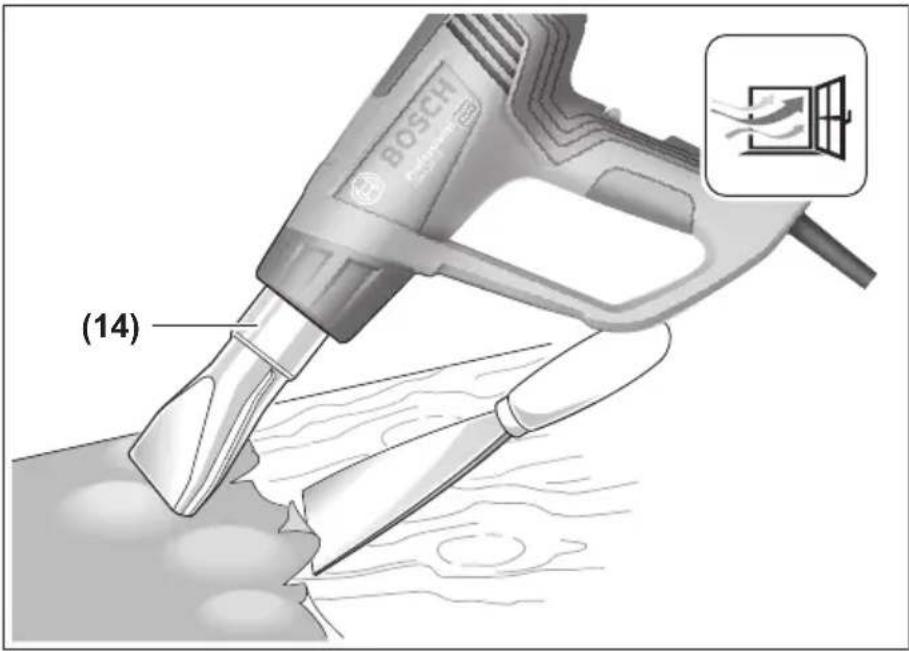
(14) Surface nozzle ^A)
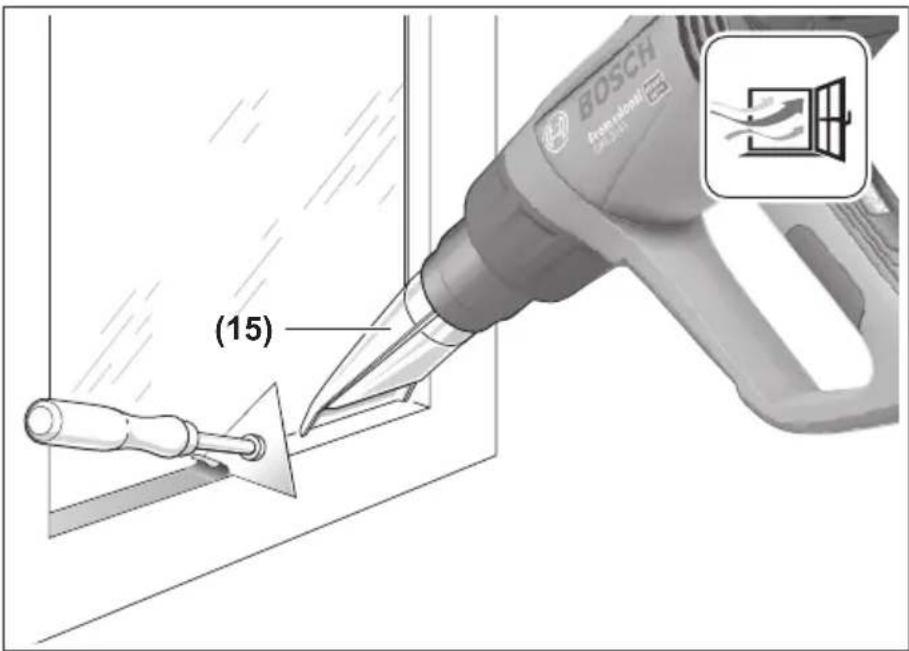
(15) Glass protection nozzle ^4
(16) Angle nozzle ^A)
(17) Reflector nozzle ^A)
(18) Welding wire ^A)
(19) Welding shoe ^A)
(20) Reducing nozzle ^A)
(21) Heat shrink plastic tube ^4)
A) Accessories shown or described are not included with the product as standard. You can find the complete selection of accessories in our accessories range.
Technical Data
| Heat gun GHG 20-63 GHG 20-63 GHG 20-63 GHG 23-66 | ||||
| Article number | 3 601 BA6 2.. | 3 601 BA6 2D. | 3 601 BA6 2C. | 3 601 BA6 3.. |
| 3 601 BA6 2G. | ||||
| Rated power input W 2000 1600 1500 2100 (2300) | A) | |||
| Airflow l/min 150/150–300/ | 100/100–250/ | 100/100–250/ | 150–300/ | |
| 300–500 | 200–350 | 200–350 | 150–500 | |
| Temperature at the nozzle outletB) | °C 50–630 50–630 50–600 50–650 | |||
| Temperature measurement accuracy | ||||
| – at the nozzle outlet ±10 % ±10 % ±10 % ±10 % | ||||
| – on the display ±5 % ±5 % ±5 % ±5 % | ||||
| Operating temperature of displayC) | °C 0 to +50 0 to +50 0 to +50 0 to +50 | |||
| Max. permissible ambient temperature during operation | °C | 40 | 40 | 40 |
| Weight according to EPTA-Procedure 01:2014 | kg | 0.65 | 0.65 | 0.67 |
| Protection class | ☐ /II | ☐ /II | ☐ /II | |
A) Maximum possible input power
B) At an ambient temperature of approx. 20 °C
C) The display may go blank if outside the operating temperature.
The specifications apply to a rated voltage [U] of 230 V. These specifications may vary at different voltages and in country-specific models.
Noise/vibration information
Typically, the A-weighted sound pressure level of the power tool is less than 70 dB(A).
Vibration total values a_h (triax vector sum) and uncertainty K: a_h ≤ 2.5 m/s^2 , K = 1.5 m/s^2 .
Operation
Starting Operation
▶ Pay attention to the mains voltage. The voltage of the power source must match the voltage specified on the rating plate of the power tool.
Creation of Smoke During Initial Use
A coating protects the metal surfaces from corrosion ex-works. This protective layer evaporates during initial use.
Switching On
Slide the on/off switch (4) upwards.
Thermal protection shutdown: If the power tool overheats (e.g. due to a build-up of air), the heating system will automatically switch off, though the blower will continue to run. Once the power tool has cooled back down to its operating temperature, the heating system will automatically switch on again.
Switching Off
Slide the on/off switch (4) downwards into the 0 position.
▶ After working at high temperatures for a prolonged period, let the power tool cool down before switching it off. To do this, allow it to run on the lowest temperature setting for a short while.
Regulating airflow (GHG 20-63)
With the on/off switch (4), you can set the airflow to one of several different levels:
Airflow setting l/min °C
| 150 50 | |
| 150-300 50-630 | |
| 300-500 50-630 |
The specifications apply to a rated voltage [U] of 230 V. These specifications may vary at different voltages and in country-specific models.
Reduce the airflow, for instance, if the area surrounding a workpiece cannot tolerate excessive heat or if a workpiece is light enough that the airflow might move it.
Regulating temperature (GHG 20-63)
On the lowest airflow setting, the temperature is set to 50 °C. In the other two airflow settings, the temperature can be adjusted.
When switching from the lowest airflow setting to another setting, the temperature last set is called up again.
To increase the temperature, press "+" on the (12) button; to decrease the temperature, press "−".
Briefly pressing the (12) button increases or decreases the temperature by 10^ C. Pressing and holding down the button
continuously increases or decreases the temperature by 10 °C until the button is released or the maximum/minimum temperature is reached.
The set target temperature is shown in the display for three seconds. The actual temperature at the nozzle output is displayed and the unit of measure for the temperature (6) flashes until the target temperature is reached. The unit of measure for the temperature stops flashing once the target temperature is reached.
▶ If you reduce the temperature, it takes a little while for the power tool to cool down.
The lowest airflow setting is suitable for cooling down a heated workpiece or for drying paint. It is also suitable for cooling down the power tool before putting it down or changing the attachment nozzles.
Regulating airflow (GHG 23-66)
In switch position 1 on the on/off switch (4), you can adjust the airflow in ten increments between 150 and 300 l/min. In switch position 2, you can adjust the airflow in ten increments between 150 and 500 l/min.
Alternatively, you can use airflow/temperature combinations that have been stored in the memory, (see "Saving airflow/temperature combinations (GHG 23-66)", page 9).
The set airflow is displayed with the ten bar segments (9) at the lower edge of the display.
Switch position I/min °C
| 1 | 150-300 50 |
| 2 | 150-500 50-650 |
To adjust the airflow, first press the fan button (10). The fan symbol (8) in the display flashes. Now you can adjust the airflow using the plus/minus button (12).
To increase the airflow, press "+" on the (12) button; to decrease the airflow, press "−".
If you wish to adjust the temperature again using the plus/ minus button (12), press the fan button (10) again. The fan symbol (8) in the display stops flashing.
If you move from switch position 1 to position 2, the airflow/temperature combination last used in position 2 is set.
Reduce the airflow, for instance, if the area surrounding a workpiece cannot tolerate excessive heat or if a workpiece is light enough that the airflow might move it.
Regulating temperature (GHG 23-66)
In switch position 1 on the on/off switch (4), the temperature is fixed at 50 °C. In switch position 2, you can adjust the temperature between 50 and 650 °C.
Alternatively, you can use airflow/temperature combinations that have been stored in the memory, (see "Saving airflow/temperature combinations (GHG 23-66)", page 9).
The set temperature is shown in the display (13).
Switch position °C l/min
| 1 | 50 150-300 |
| 2 | 50-650 150-500 |
To increase the temperature, press "+" on the (12) button; to decrease the temperature, press "−".
Briefly pressing the (12) button increases or decreases the temperature by 10 °C. Pressing and holding down the button continuously increases or decreases the temperature by 10 °C until the button is released or the maximum/minimum temperature is reached.
The set target temperature is shown in the display for three seconds. The actual temperature at the nozzle output is displayed and the unit of measure for the temperature (6)
flashes until the target temperature is reached. The unit of measure for the temperature stops flashing once the target temperature is reached.
▶ If you reduce the temperature, it takes a little while for the power tool to cool down.
Switch setting 1 is suitable for cooling down a heated workpiece or for drying paint. It is also suitable for cooling down the power tool before putting it down or changing the attachment nozzles.
Saving airflow/temperature combinations (GHG 23-66)
You can save four airflow/temperature combinations or access four saved preset combinations.
To do this, the on/off switch (4) must be set to switch position 2.
Factory settings
| Memory preset | °C I/min Application |
| 0^A) | 50 150 – Cooling down a workpiece– Drying paint |
| 1 250 350 | Shaping plastic pipes |
| 2 350 400 | Welding plastic |
| 3 450 500 | Removing varnish |
| 4 550 400 | Soft soldering |
A) Not shown in the display
To call up a combination, keep pressing the memory button (11) until the number you want appears in the display (5).
To save your own combination:
- Press the memory button (11) to select the memory preset you want.
- Set the desired temperature and airflow. The memory preset (5) flashes to indicate that the saved combination has been changed.
- Press and hold down the memory button (11). The memory preset (5) flashes for around two seconds. When it lights up continuously, the new combination has been saved.
Practical advice
▶ Pull the plug out of the socket before carrying out any work on the power tool.
Note: Do not position the nozzle (1) too close to the workpiece that you are using the power tool on. The resulting build-up of air can cause the power tool to overheat.
Removing the heat shield
When working in particularly tight spaces, you can remove the heat shield (2) by turning it.
▶ Caution: Nozzle is hot! Working without the heat shield increases the risk of burns.
Always switch the power tool off and allow it to cool before removing or attaching the heat shield (2).
To make the power tool cool down quicker, you can also let it run briefly on its lowest temperature setting.
Setting Down the Power Tool
Set the power tool down on the storage surfaces (3) to leave it to cool down or to keep both hands free to work with.
▶ Take particular care when working in the vicinity of the power tool while it has been set aside. The heat from the nozzle or the air flow can cause burns.
Position the power tool on an even, stable surface. Ensure that it cannot tip over. Secure the cable outside of your working area so that it cannot pull the power tool down or cause it to flip over.
Switch the power tool off when not in use for a long period and pull the mains plug out of the socket.
Example applications (see figures A–G)
Images of example applications can be found on the graphics pages.
The distance between the nozzle and the workpiece depends on the material you are working on (metal, plastic etc.) and the intended working method.
The optimum temperature for each application can be determined by a practical test.
Always test the amount of air and temperature first. Start at a greater distance and a lower power setting. Then adjust the distance and power setting according to requirements. If you are unsure what material you are working on or what effect the hot air might have on it, first test the effect on a concealed area.
All example applications apart from "Stripping paint from window frames" can be carried out without the use of accessories. However, using the recommended accessories will simplify the work and considerably increase the quality of the result.
▶ Take care when changing the nozzle. Do not touch the nozzle while it is hot. Leave the power tool to cool down before changing the nozzle, and wear protective gloves when doing so. The heat from the nozzle can cause burns.
To make the power tool cool down quicker, you can also let it run briefly on its lowest temperature setting.
Removing varnish/loosening adhesives(see figure A)
Fit the surface nozzle (14) (accessory). Briefly soften the varnish with hot air and remove it with a clean spatula. Long heat exposure burns the varnish and makes removal more difficult.
Many adhesives can be softened using heat. By heating adhesives, you can break connections or remove excess adhesive.
Stripping Paint from Window Frames (see figure B)
The glass protection nozzle (15) (accessory) must be used for this application. There is a risk that the glass may break.
You can remove the paint from profiled surfaces with a suitable spatula and brush it off with a soft wire brush.
Thawing frozen water pipes (see figure C)
▶ Before applying heat to the pipe, check it is in fact a water pipe. Water pipes and gas pipes often look identical from the outside. Gas pipes must under no circumstances be heated.
Fit the angle nozzle (16) (accessory). Gradually heat the frozen points of the pipe, starting at the outlet and moving back towards the inlet.
Take great care when warming plastic pipes and pipe connections to avoid causing damage.
Shaping plastic pipes (see figure D)
Fit the reflector nozzle (17) (accessory). Fill plastic pipes with sand and seal them on both sides to prevent the pipe bending. Carefully and evenly heat the pipe by moving the tool back and forth from one side to the other.
Welding plastic (see figure E)
Fit the reducing nozzle (20) and the welding shoe (19) (both accessories). The workpiece requiring welding and the welding wire (18) (accessory) must be made from the same material (e.g. both PVC). The seam must be clean and free from grease.
Heat the point of the seam carefully until it becomes pliable. Note that there is not a great difference in temperature between pliable plastic and liquid plastic.
Apply the welding wire (18) and allow it to flow into the joint to form an even bead.
Soft Soldering (see figure F)
For spot welding, fit the reducing nozzle (20); for welding pipes, fit the reflector nozzle (17) (both accessories).
If you are using solder without flux, apply soldering grease or paste to the solder joint. Depending on the material, heat the solder joint for approx. 50 to 120 seconds. Apply the solder. The solder must be melted by the temperature of the workpiece.
If necessary, remove the flux after the solder joint has cooled down.
Heat-shrinking (see figure G)
Fit the reflector nozzle (17) (accessory). Choose the diameter of the heat shrink plastic tube (21) (accessory) suitable for the workpiece. Evenly heat the heat shrink plastic tube until it fits closely against the workpiece.
Maintenance and Servicing
Maintenance and Cleaning
▶ Pull the plug out of the socket before carrying out any work on the power tool.
▶ To ensure safe and efficient operation, always keep the power tool and the ventilation slots clean.
In order to avoid safety hazards, if the power supply cord needs to be replaced, this must be done by Bosch or by a customer service centre that is authorised to repair Bosch power tools.
After-sales Service and Advice on Using Products
Our after-sales service can answer questions concerning product maintenance and repair, as well as spare parts. You can find exploded drawings and information on spare parts at: www.bosch-pt.com
The Bosch product use advice team will be happy to help you with any questions about our products and their accessories.
In all correspondence and spare parts orders, please always include the 10-digit article number given on the type plate of the product.
Cambodia
Robert Bosch (Cambodia) Co., Ltd Unit 8BC, GT Tower, 08th Floor, Street 169, Czechoslovakia Blvd, Sangkat Veal Vong Khan 7 Makara, Phnom Penh VAT TIN: 100 169 511 Tel.: +855 23 900 685 Tel.: +855 23 900 660 www.bosch.com.kh
People's Republic of China China Mainland
Bosch Power Tool (China) Co. Ltd. Bosch Service Center 567, Bin Kang Road Bin Kang District Hangzhou, Zhejiang Province China 310052 Tel.: (0571) 8887 5566 / 5588 Fax: (0571) 8887 6688 x 5566# / 5588# E-mail: bsc.hz@cn.bosch.com www.bosch-pt.com.cn
HK and Macau Special Administrative Regions Robert Bosch Co. Ltd.
21st Floor, 625 King's Road North Point, Hong Kong Customer Service Hotline: +852 2101 0235 Fax: +852 2590 9762
E-mail: info@hk.bosch.com
www.bosch-pt.com.hk
India
Bosch Service Center
69, Habibullah Road, (next to PSBB School), T. Nagar
Chennai-600077
Phone: (044) 64561816
Bosch Service Center Rishyamook
85A, Panchkuin Road
New Delhi-110001
Phone: (011) 43166190
Bosch Service Center 79,
Crystal Bldg., Dr. Annie Besant Road, Worli
Mumbai-400018
Phone: (022) 39569936 / (022) 39569959 /
(022) 39569967 / (022) 24952071
Indonesia
PT Robert Bosch
Palma Tower 10th Floor
Jalan RA Kartini II-S Kaveling 6
Pondok Pinang, Kebayoran Lama
Robert Bosch Middle East FZE – Pakistan Liaison Office
2nd Floor Plaza # 10, CCA Block, DHA Phase 5
Lahore, 54810
Phone: +92(303)4444311
E-mail: Faisal.Khan@bosch.com
Philippines
Robert Bosch, Inc.
28th Floor Fort Legend Towers,
3rd Avenue corner 31st Street,
Fort Bonifacio, Global City,
1634 Taguig City
Tel.: (632) 8703871
Fax: (632) 8703870
www.bosch-pt.com.ph
Singapore
Powerwell Service Centre Ptd Ltd
Bosch Authorised Service Centre (Power Tools)
4012 Ang Mo Kio Ave 10, #01-02 TECHplace
Singapore 569628
Tel.: 6452 1770
Fax: 6452 1760
E-mail: ask@powerwellsc.com
www.powerwellsc.com
www.bosch-pt.com.sg
Thailand
Robert Bosch Ltd.
Liberty Square Building
No. 287, 11 Floor
Silom Road, Bangrak
Bangkok 10500
Tel.: 02 6393111
Fax: 02 2384783
Robert Bosch Ltd., P. O. Box 2054
Bangkok 10501
www.bosch.co.th
Bosch Service – Training Centre
La Salle Tower Ground Floor Unit No.2
10/11 La Salle Moo 16
Srinakharin Road
Bangkaew, Bang Plee
Samutprakarn 10540
Tel.: 02 7587555
Fax: 02 7587525
Vietnam
Branch of Bosch Vietnam Co., Ltd in HCMC
14th floor, Deutsches Haus, 33 Le Duan
Ben Nghe Ward, District 1, Ho Chi Minh City
Tel.: (028) 6258 3690
Fax: (028) 6258 3692 - 6258 3694
Hotline: (028) 6250 8555
E-mail: tuvankhachhang-pt@vn.bosch.com
www.bosch-pt.com.vn
Armenia, Azerbaijan, Georgia, Kyrgyzstan, Mongolia,
Tajikistan, Turkmenistan, Uzbekistan
TOO "Robert Bosch" Power Tools, After Sales Service
Rayimbek Ave., 169/1
050050, Almaty, Kazakhstan
Service e-mail: service.pt.ka@bosch.com
Official website: www.bosch.com, www.bosch-pt.com
Bahrain
Hatem Al Juffali Technical Equipment Establishment.
Kingdom of Bahrain, Setra Highway, Al Aker Area
Phone: +966126971777-311
Fax: +97317704257
E-mail: h.berjas@eajb.com.sa
Egypt
Unimar
20 Markaz kadmat
El tagmoa EL Aoul – New Cairo
Phone: +20 2224 76091-95
Phone: +20 2224 78072-73
Fax: +20222478075
E-mail: adelzaki@unimaregypt.com
Iran
Robert Bosch Iran
3rd Floor, No 3, Maadiran Building
Aftab St., Khodami St., Vanak Sq.
Tehran 1994834571
Phone: +9821 86092057
Iraq
Sahba Technology Group
Al Muthana airport road
Baghdad
Phone: +9647901906953
Phone Dubai: +97143973851
E-mail: bosch@sahbatechnology.com
Jordan
Roots Arabia – Jordan
Nasser Bin Jameel street, Building 37 Al Rabiah
11194 Amman
Phone: +962 6 5545778
E-mail: bosch@rootsjordan.com
Kuwait
Al Qurain Automotive Trading Company
Shuwaikh Industrial Area, Block 1, Plot 16, Street 3rd
P.O. Box 164 - Safat 13002
Phone: 24810844
Fax: 24810879
E-mail: josephkr@aaalmutawa.com
Lebanon
Tehini Hana & Co. S.A.R.L.
P.O. Box 90-449
Jdeideh
Dora-Beirut
Phone: +9611255211
E-mail: service-pt@tehini-hana.com
Libya
El Naser for Workshop Tools
Swanee Road, Alfalah Area
Tripoli
Phone: +218 21 4811184
Oman
Malatan Trading & Contracting LLC
P.O. Box 131
Ruwi, 112 Sultanate of Oman
Phone: +968 99886794
E-mail: malatanpowertools@malatan.net
Qatar
International Construction Solutions W L L
P. O. Box 51,
Doha Phone: +974 40065458
Fax: +974 4453 8585
E-mail: csd@icsdoha.com
Saudi Arabia
Juffali Technical Equipment Co. (JTECO)
Kilo 14, Madinah Road, Al Bawadi District
Jeddah 21431
Phone: +966 2 6672222 Ext. 1528
Fax: +966 2 6676308
E-mail: roland@eajb.com.sa
Syria
Dallal Establishment for Power Tools
P.O. Box 1030
Aleppo
Phone: +963212116083
E-mail: rita.dallal@hotmail.com
United Arab Emirates
Central Motors & Equipment LLC, P.O. Box 1984
Al-Wahda Street – Old Sana Building
Sharjah
Phone: +971 6 593 2777
Fax: +971 6 533 2269
E-mail: powertools@centralmotors.ae
Yemen
Abualrejal Trading Corporation
Sana'a Zubiery St. Front to new Parliament Building
Phone: +967-1-202010
Fax: +967-1-279029
E-mail: tech-tools@abualrejal.com
Ethiopia
Forever plc
Kebele 2,754, BP 4806,
Addis Ababa
Phone: +251 111 560 600
E-mail: foreverplc@ethionet.et
Ghana
C.WOERMANN LTD.
Nsawam Road/Avenor Junction, P.O. Box 1779
Accra Phone: +233 302 225 141
Kenya
Robert Bosch East Africa Ltd
Mpaka Road P.O. Box 856
00606 Nairobi
Nigeria
Robert Bosch Nigeria Ltd.
52–54 Isaac John Street P.O. Box
GRA Ikeja – Lagos
Republic of South Africa
Customer service
Hotline: (011) 6519600
Gauteng - BSC Service Centre
35 Roper Street, New Centre
Johannesburg
Tel.: (011) 4939375
Fax: (011) 4930126
E-mail: bsctools@icon.co.za
KZN - BSC Service Centre
Unit E, Almar Centre
143 Crompton Street
Pinetown
Tel.: (031) 7012120
Fax: (031) 7012446
E-mail: bsc.dur@za.bosch.com
Western Cape – BSC Service Centre
Democracy Way, Prosperity Park
Milnerton
Tel.: (021) 5512577
Fax: (021) 5513223
E-mail: bsc@zsd.co.za
Bosch Headquarters
Midrand, Gauteng
Tel.: (011) 6519600
Fax: (011) 6519880
E-mail: rbsa-hq.pts@za.bosch.com
Tanzania
Diesel & Autoelectric Service Ltd.
117 Nyerere Rd., P.O. Box 70839
Vingunguti 12109, Dar Es Salaam
Phone: +255 222 861 793/794
Australia, New Zealand and Pacific Islands
Robert Bosch Australia Pty. Ltd.
Power Tools
Locked Bag 66
Clayton South VIC 3169
Customer Contact Center
Inside Australia:
Phone: (01300) 307044
Fax: (01300) 307045
Inside New Zealand:
Phone: (0800) 543353
Fax: (0800) 428570
Outside AU and NZ:
Phone: +61 3 95415555
www.bosch-pt.com.au
www.bosch-pt.co.nz
Disposal
The power tool, accessories and packaging should be recycled in an environmentally friendly manner.
Do not dispose of power tools along with household waste.
Français
Robert Bosch Morocco SARL
53, Rue Lieutenant Mahroud Mohamed
20300 Casablanca
E-Mail : sav.outillage@ma.bosch.com
Tunisie
Robert Bosch Tunisie SARL
Calle Robert Bosch No. 405
(12) Tombol plus/minus
(13) Display
(14) Nozel pipih ^A)
(15) Nozel pelindung kaca ^A)
(16) Nozel sudut ^A)
(17) Nozel reflektor ^A)
Heat gun GHG 20-63 GHG 20-63 GHG 20-63 GHG 23-66
| – pada display ±5% ±5% ±5% ±5% | ||||
| Display pengoperasian suhuC) | °C 0...+50 0...+50 0...+50 0...+50 | |||
| Suhu sekitar maks. yang diperbolehkan saat pengoperasian | °C 40 40 40 40 | |||
| Berat sesuai dengan EPTA-Procedure 01:2014 | kg 0,65 0,65 0,65 0,67 | |||
| Klasifikasi keamanan | ☐/II | ☐/II | ☐/II | ☐/II |
Palma Tower 10th Floor
Jalan RA Kartini II-S Kaveling 6
Pondok Pinang, Kebayoran Lama
GHG 20-63GHG 20-63GHG 20-63GHG 23-66
11/回
11/回
11/回
11/回
كلاس ايمنى
A(دار توان)
B(ط hypod)
C(٠. و بشد).
مCADIR PRAYO WILTAJNA 230 [U] wt mejashnd. BRAYO WILTAJHAIE MCHTLF OTOLIDAT MCHUSK KSHORHAA, MMKN ASST AIN MCAADIR, MTFAOT BAISHN.