
SBCVL1405 - Headphones PHILIPS - Free user manual and instructions
Find the device manual for free SBCVL1405 PHILIPS in PDF.
| Product type | Wireless TV link receiver |
| Brand | Philips |
| Model | SBCVL1405 |
| Dimensions | 6.1 cm (W) × 14.6 cm (D) × 15 cm (H) |
| Weight | Approximately 300 g |
| Power supply | 220-240 V / 50 Hz via 12 V DC / 300 mA power adapter |
| Power consumption | 7 W (transmitter and receiver) |
| Compatible video standards | PAL / NTSC / SECAM |
| Audio/video carrier frequency | 2.4 GHz |
| Number of transmission channels | 4 channels (depending on local regulations) |
| Range | Up to 100 m outdoors, up to 30 m indoors |
| SCART connectors | 4 inputs, 1 output |
| Audio output | Stereo RCA |
| Main functions | Wireless reception of video/audio signals, source selection, IR remote control |
| Maintenance and cleaning | Clean with a soft, dry cloth. Do not use abrasive products. |
| Safety | Do not open the device. Avoid moisture and heat sources. Use only the supplied adapter. |
| Spare parts and repairability | Power adapter supplied. In case of problems, contact Philips after-sales service. |
| General information | Works with the Philips SBC VL1400 transmitter. Allows viewing video sources on a secondary TV. |
Frequently Asked Questions - SBCVL1405 PHILIPS
User questions about SBCVL1405 PHILIPS
0 question about this device. Answer the ones you know or ask your own.
Ask a new question about this device
Download the instructions for your Headphones in PDF format for free! Find your manual SBCVL1405 - PHILIPS and take your electronic device back in hand. On this page are published all the documents necessary for the use of your device. SBCVL1405 by PHILIPS.
USER MANUAL SBCVL1405 PHILIPS
Instructions for use
A) TRANSMITTER part of SBC VL1400 (not supplied)
B) RECEIVER
Helpline
Belgie & Luxemburg/
Belgien & Luxemburg/
R&TTE Directive 1999/5/EC
| BE | ✓ | DK | ✓ | GR | ✓ | ES | X | FR | ✓ |
| IRE | X | IT | ✓ | LU | ✓ | NL | ✓ | AT | ✓ |
| PT | ✓ | FI | ✓ | SE | ✓ | UK | X | NO | ✓ |
| DE | ✓ | CH | ✓ |
SBC VL1405/05
R&TTE Directive 1999/5/EC
| BE X | DK X | GR X | ES X | FR X |
| IRE √ | IT X | LU X | NL X | AT X |
| PT X | FI X | SE X | UK √ | NOX |
| DE X | CH X |
SBC VL1405/16
R&TTE Directive 1999/5/EC
| BE X | DK X | GR X | ES √ | FR X |
| IRE X | IT X | LU X | NL X | AT X |
| PT X | FI X | SE X | UK X | NOX |
| DE X | CH X |

Wireless TV Link
SBC VL1405
The Philips Wireless TV link Receiver VL1405 you have just purchased is manufactured to the highest standards and will give you years of trouble free use. The Philips Wireless TV link Receiver is designed to be used in addition to the Philips Wireless TV link, type number SBC VL1400. Please read the following instructions carefully, and retain this booklet for future reference. This booklet will only describe the installation and use of the Wireless TV Receiver VL1405. For instructions on the Philips Wireless TV link VL1400 (ie Remote Control usage, linking video sources, setting up transmitter uni) we refer to the original instructions booklet.
The Philips Wireless TV Link Receiver allows you to receive the video signal transmitted by the Philips Wireless TV link in another location.
The Wireless TV Link Receiver is based on wireless RF technology. To enable you to enjoy the best possible performance, four transmission channels are provided so you can select the channel that provides optimum viewing with the minimum of interference. Pure wireless home convenience!
Important information
- Please read the following instructions carefully, and retain this booklet for future reference.
Each video source, the main TV and the second TV must have SCART connectors.
-
Two SCART cables are supplied; you will require additional SCART cables for the video sources you connect.
-
A video source can be any satellite receiver, Pay-TV decoder box (digital or analogue), video recorder (VCR), DVD player, camcorder, game-conSOLE, PC with TV-out capability, etc.
-
In these instructions for use we refer to the connected TV's as follows: - TV1 - The main TV, connected to the transmitter unit of the Wireless TV link VL1400.
-
TV2 - The second TV, connected to the receiver unit of the Wireless TV link VL1400.
-
TV3 - The third TV, connected to the VL1405 receiver.
-
It may be helpful to have the instructions for use for the TVs and the video sources at hand for reference.
Note: This product will not operate remote control signals (IRDA) of set-top boxes providing NTL or Telewest cable TV services. A similar issue may arise in the unlikely event that other service providers use the IRDA signals. Please check with your service provider.
Safety precautions
- Do not use this product in damp places or close to water.
- Do not expose this product to extreme heat.
- Do not open this product.
In the event of technical difficulties take it to your Philips retailer.
- Do not cover this product.
- Only connect the AC power adapters to a power supply of 220-240 V AC/ 50Hz.
- Only use the AC power adapters included or a type that complies with safety standard EN60950 and that has the following specification: 12VDC / 500mA .
- Inadequately protected or sensitive electronic equipment may be affected by the use of this product. This interference may lead to damage to either equipment. Please check whether or not surrounding equipment may be affected by this product before you start using it.
Packaging contents
Please check that the following items are packed in the Wireless TV Link receiver box. They are provided to help you set up and use your Wireless TV Link receiver.
- Receiver unit
- AC power adapter
SCART/RCA audio/video cable - Instructions for use
Functional overview - Product illustrations on inside flap
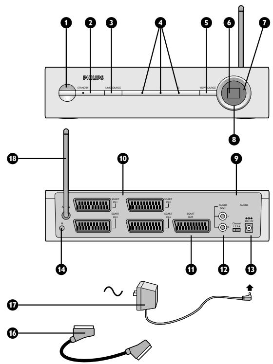
A)Transmitter unit SBC VL1400 (not supplied)
1 Power button
switches the transmitter between stand-by and on.
2 Power light
lights red in stand-by mode, green when power is on, flashes when receiving remote control commands
3 COPY SOURCE button
links SCART input 1,2,3 or SCART OUT to SCART in/output 4.
4 Copy source indication lights
indicate which SCART input (1,2 or 3) is linked to SCART in/output 4. When there is no light indication the SCART OUT is linked to SCART in/output 4.
5 VIEW SOURCE button
selects which SCART input (1-4) is viewed on the transmitter SCART output
6 View source indication display
indicates the SCART input number that is viewed on the transmitter output.
7 AUTO light
indicates if automatic SCART switching is enabled (on) or disabled (off).
8 Infra-red remote control blaster lights
transmit infra-red remote control signals from the receiver to the video source devices below.
9 Transmission channel switch
switches the frequency channel of the audio/video signal to minimize interference.
10 SCART input (1-4) connectors
for connection to SCART-enabled video source devices
11 SCART output connector
for connection to the main TV
12 RCA sound output connector
for connection to an audio amplifier
13 DC power input
for connection to the mains
14 Remote control blaster cord connector
15 Remote control blaster cord
four infra-red lights used instead of the infra-red remote control blaster lights (A-8) for a more precise control of the video sources.
16 SCART cable
17 Power adapter
18 Remote control antenna
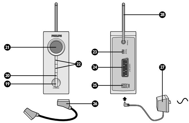
B) Receiver unit
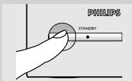
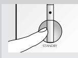
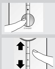
19 Power button
switches the receiver between stand-by and on. When the receiver unit is turned on or off the transmitter unit is automatically turned on or off as well.
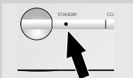
20 Power light
lights red in stand-by mode, green when power is on, flashes when receiving remote control commands
21 Remote control signal receiver
receives remote control commands which are sent to the transmitter unit to control the video sources.
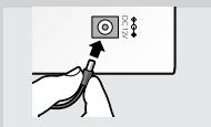
22 Input source up (+) / down (-) buttons
selects one of the four video sources connected to the transmitter unit for viewing on the third TV
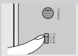
23 Transmission channel switch
switches the frequency channel of the audio/video signal to minimize interference.
24 SCART output connector
for connection to the third TV
25 DC power input
for connection to the mains
26 SCART cable
27 Power adapter
28 Remote control antenna
Getting your Wireless TV Link ready
Setting up the Wireless TV Link SBC VL1400
1 Set up transmitter and receiver unit of the Wireless TV Link as described in the instructions for use that came with the set.
Make sure both units are set to the same channel.
2 Switch on the transmitter unit.
You can now setup and test the additional receiver.
Setting up the receiver unit
1 Set the Transmission channel switch (B-23) to the same channel as the transmitter.
2 Position the additional receiver unit close to TV3.
Ensure that the front of the receiver unit is positioned to receive remote control commands.
3 Connect SCART cable from receiver unit to TV3.
4 Connect the power adapter to receiver unit.
5 Plug the power adapter of the additional receiver into mains socket.
Checking the remote control operation
1 Switch on TV3 and the receiver unit.
Make sure your transmitter is also switched on.
2 Point the video source's remote control unit at the receiver unit and switch between play and stop.
The power light (B-19) on the receiver unit flashes to show that it has received the remote control command.
3 Have a second person check that the power light (A-1) on the transmitter unit flashes.
This indicates that it is receiving the remote control signal from the receiver unit.
4 If the power light (A-1) does not flash, reposition the remote control antenna at the rear of the additional receiver unit (B-28).
The power light on the transmitter unit should now flash when a remote control command is given at the receiver side. If the VL1400 Wireless TV link was working correctly before you installed the additional VL1405 Receiver the video source should response.
5 If the video source does not respond to the remote command, try realigning the front of the transmitter unit with the front of the video source until you get a response.
6 If the video source still fails to respond install the remote control blaster cord as described in the instructions for use of the VL1400 Wireless TV link.
Using the wireless link with TV3
Watching and controlling video sources on TV3
1 Switch on TV3. This is the TV that is connected to the VL1405 receiver. It is not necessary to switch on TV1 to enjoy video programmes on TV3.
2 Press the power button (B-19) to switch on the receiver unit.
When the receiver unit is switched on, the transmitter unit switches on automatically and TV3 displays the signal on its SCART input.
3 Press the - or + buttons (B-22) on the receiver unit to select the video source to be displayed.
The selection cycle is SCART input 1 > 2 > 3 > 4
4 Aim the remote control at the receiver unit to control the video source.
| Problem solving | |
| If a fault occurs, first check the points listed below. If you are unable to remedy a problem by following these hints, contact the helpline (see "Need help?") or consult your dealer. Never try to open the set yourself as this will void the guarantee. First, check all cables to ensure that they are connected correctly. | |
| Problem | Solution |
| No picture on TV3 | ·Ensure that both units are switched on (A-2 and B-20 are green). ·Select the EXT or AV channel on TV3. ·Activate the video source (set-top box: power on; VCR/DVD: playback). ·Select the correct video source on the Receiver unit. ·Select the same frequency channel on both the Receiver and Transmitter units. ·If a VCR is the video source, ensure that the correct SCART connector of the VCR is used (Ext1 or Ext2 - check VCRs user manual). |
| Bad picture/sound quality on TV3 | ·Move the receiver unit around gently until you get good picture and sound quality. ·Move the transmitter unit around gently until you get good picture and sound quality. ·Change both units to another frequency channel. ·Reduce the distance between the transmitter and receiver unit (<30m). |
| The cable programme you are watching disappears after several minutes | ·Disable the auto standby mode of the VCR. (Check VCR's User Manual). |
| Wrong picture on TV3 | ·Select the EXT or AV channel on TV3. ·Select another video source on the receiver unit. ·Activate the video source (set-top box: power on; VCR/DVD: playback). ·Swap the SCART connectors on the transmitter unit. ·Switch to another frequency channel on both units. |
| Wrong picture on TV1 | ·Select the correct EXT or AV channel on TV1 (see TV instruction manual). ·Select the correct video source with the VIEW SOURCE button (A-5). ·Select a regular programme number. |
| No control of video sources from TV3 | • Aim the remote control directly at the receiver unit and ensure that there are no obstacles in between (B-19 must flash). • Ensure that there is no other wireless device (wireless headphones, speakers, RF control signals) interfering with the remote control. • The maximum operating distance between the remote control and the receiver unit is 6 metres*; make sure you are within this range. • Ensure that the transmitter and receiver unit are more than 5 metres apart. • Ensure that the remote control belonging to the video source is used to control it. • Reposition the remote control blaster cord light on the video source, or place the light 5-10 cm in front of the video source. |
| Buzzing sound when using the remote control | • Move the receiver unit around gently until the buzzing sound stops. • Move the transmitter unit around gently until the buzzing sound stops. • With some types of TV you will not be able to solve this problem. |
| Easylink feature doesn’t work | • Check that both your TV and VCR support this feature (check TV and VCRs user manuals). • Use Easylink compatible or fully wired SCART cables. |
| S-VHS video gives black and white pictures only | • Select CVBS video output format for your S-VHS VCR when using SCART input 1 or 2 (check the VCRs user manual). |
| DVD player gives no pictures on TV1, TV2 or TV3 | • Connect the DVD player to SCART input 3 or 4 (both support RGB). • Select CVBS video output format for your DVD player (check the DVD player’s user manual). * depends on remote control's signal strength and battery condition. |
General notes
- Picture and sound quality is influenced by the use of microwave ovens. Other wireless systems (Bluetooth, wireless LANs, etc.) can also adversely influence the quality of picture and sound, and vice versa.
- The Wireless TV Link is a Radio Frequency (RF) based product. As such its performance can suffer the same kinds of interference as GSMs, portable radios and other RF-based products.
- If the same video source is selected for both TVs, then you get the same programme on each TV.
- The Wireless TV link is not limited to just one room or house. You can use it anywhere in or around the house. Consequently, anybody in the vicinity of your house (up to the maximum operating range) who also owns a Wireless TV link set to the same channel, can watch the same programmes that are playing on your video source.
- In order to prevent the mixing of remote control commands it is not advisable to use a TV as a video source.
- Some built-in VCRs (TV-VCR combination) cannot be used with the transmitter unit (depends on brand and type).
- Video sources cannot be controlled remotely if the carrier frequency of the IR signal is outside the operation window of 32kHz to 57kHz .
- Radio wave safety: When switched on, the Philips Wireless TV Link transmits and receives radio waves. The Philips Wireless TV Link complies with the standards that are defined for it.
- The transmitter unit can support the channel downloading feature (also known as 'Follow-TV', 'Easylink', 'SmartLink', 'AV-Link', 'MEGALogic', 'TV-Link' or 'Q-Link') of high-end TVs and VCRs. Fully wired SCART cables that support this feature must be used.
- The Philips Wireless TV Link has an operating range of up to 100 metres in open air. Walls, ceilings and other large objects may limit the useable operating range to about 30 metres in the house.
| Technical specifications | ||
| General | Video standards supported: | PAL / NTSC / SECAM |
| Power supply: | 220 - 240V AC / 50Hz | |
| Operating consumption: | 7 W (both transmitter and receiver unit) | |
| Receiver unit | SCART Connector: | Output stereo audio/video: CVBS |
| Video standards supported: | PAL / NTSC / SECAM | |
| Operating range: | Up to 100 metres in open air; up to 30 metres indoors | |
| Dimensions: | 6.1 cm (W) x 14.6 cm (D) x 15 cm (H) | |
| Audio / Video transmission | Carrier frequency: | 2.4 GHz |
| Number of channels: | four (maybe fewer, depending on local regulations) | |
| Type of modulation: | FM | |
| Transmission power: | <10mW | |
| Antennas: | Built-in | |
| Remote control transmission | Carrier frequency: | 433.92 MHz |
| Type of modulation: | AM | |
| Transmission power: | <10 mW | |
| Range of IR reception: | Up to 6 metres | |
| Carrier frequency range | 32 kHz – 57 kHz | |
| Remote control blaster cord: | Yes, 4 infrared lights | |
| Remote control antenna: | Antennas at rear of receiver | |
Need Help?
In case you have any questions about the VL1405, please contact our helpline for assistance! You can find the number in the list on page 2.
Before you call, please read this manual carefully. You will be able to solve most of your problems.
The model number of the Wireless TV Link is VL1405.
Date of purchase: day /month /year
Liaison TV sans fil
SBC VL1405
Make sure your transmitter is also swiched on.
13 Inngang for likestrøm
25 Inngang for likestrøm
5 VIEW SOURCE -painike
www.philips.com
This document is printed on chlorine free produced paper
Data subject to change without notice
Printed in China
C∈0682①
