
SBCLM1000 - Bluetooth speaker PHILIPS - Free user manual and instructions
Find the device manual for free SBCLM1000 PHILIPS in PDF.

| Product type | Wireless PC-TV extender (transmitter/receiver) |
| Brand | PHILIPS |
| Model | SBCLM1000 |
| Dimensions (transmitter and receiver) | 14.3 cm (L) × 9.3 cm (W) × 4 cm (H) |
| Weight (approx. per unit) | Approx. 200 g |
| Power supply | 220-240 V ~ 50 Hz via 9 V DC/300 mA mains adapter |
| Power consumption (transmitter + receiver) | 3 W |
| Main functions | Wirelessly transmits audio/video signals from PC to TV (range up to 30 m indoors) |
| Supported video standards | PAL / NTSC / SECAM |
| Audio/video inputs (transmitter) | RCA connectors: video (yellow), left audio (white), right audio (red) + 3.5 mm jack socket |
| Audio/video outputs (receiver) | RCA connectors: video (yellow), left audio (white), right audio (red) + SCART adapter included |
| Transmission frequency | 2.4 GHz (FM modulation) |
| Number of channels | 4 (selectable via switch) |
| Maximum range | Up to 100 m in open space, 30 m indoors |
| Transmission power | < 10 mW |
| Antennas | Built-in |
| Maintenance and cleaning | Do not open the casing; clean with a dry cloth; do not expose to humidity or extreme heat |
| Safety | Use only the supplied adapter; do not cover the device; avoid interference with other RF equipment |
| Package contents | Transmitter, receiver, two mains adapters, RCA+jack audio/video cable, RCA audio and video cables, RCA-SCART adapter, jack splitter, remote control extender, manual |
| Availability of spare parts | Contact Philips service for adapters and cables |
| Repairability | Do not open; in case of failure, contact an authorized Philips service center |
| Warranty | Standard Philips (refer to manual) |
Frequently Asked Questions - SBCLM1000 PHILIPS
User questions about SBCLM1000 PHILIPS
0 question about this device. Answer the ones you know or ask your own.
Ask a new question about this device
Download the instructions for your Bluetooth speaker in PDF format for free! Find your manual SBCLM1000 - PHILIPS and take your electronic device back in hand. On this page are published all the documents necessary for the use of your device. SBCLM1000 by PHILIPS.
USER MANUAL SBCLM1000 PHILIPS
Instructions for use
English 4
Mode d'emploi
Français 14
R&TTE Directive 1999/5/EC
| BE √ | DK √ | GR √ | ES × | FR √ |
| IRE × | IT √ | LU √ | NL √ | AT √ |
| PT √ | FI √ | SE √ | UK × | NO√ |
| DE √ | CH √ |
SBC LM 1000/05
R&TTE Directive 1999/5/EC
| BE X | DK X | GR X | ES X | FR X |
| IRE √ | IT X | LU X | NL X | AT X |
| PT X | FI X | SE X | UK √ | NOX |
| DE X | CH X |
SBC LM 1000/16
R&TTE Directive 1999/5/EC
| BE X | DK X | GR X | ES √ | FR X |
| IRE X | IT X | LU X | NL X | AT X |
| PT X | FI X | SE X | UK X | NOX |
| DE X | CH X |

4 ENGLISH
Wireless PC-TV Link
SBC LM1000
Congratulations! The Philips Wireless PC-TV Link SBC LM1000 you have just purchased is manufactured to the highest standards and will give you years of trouble-free use.
To enable you to enjoy the best possible performance, the Philips Wireless PC-TV Link has a channel selector switch, which enables you to select the channel that provides optimum viewing. Pure wireless home convenience!
Note: The Wireless PC-TV Link does NOT give you control over PC and/ or audio/video content you are playing. You need to manually start/ stop playing videos or audio songs on your PC via the connected mouse or keyboard.
Contents
Helpline 2
Illustrations 3
Introduction. 4
- Important information.. 5
Safety precautions. 5
Packaging contents. 5
- Functional overview 6-7
A) Transmitter unit 6
B) Receiver unit 7
- Installation 8-10
Setting up the transmitter unit. 8
Connecting the receiver unit to the TV. 9
Channel selection 9
Optional connection to audio equipment. 9-10
- Operation 10
- Problem solving 11-12
- General notes. 12
- Technical specifications 13
1. Important information
- Please read the following instructions carefully, and retain this booklet for future reference.
-
Requirements:
-
TV with SCART or RCA connector(s).
-
Video requirements: PC with properly installed video card, supporting TV-out. The TV-Out connector should be an RCA connector.
- Audio requirements: PC with properly installed sound card with 3.5 mm jack.
Safety precautions
- Do not use this product in damp places or close to water.
- Do not expose this product to extreme heat.
- Do not open this product. In the event of technical difficulties take it to your Philips retailer.
- Do not cover this product.
- Only connect the AC power adapters to a power supply of 220-240 V AC/ 50Hz.
- Only use the AC power adapters included or a type that complies with safety standard EN60950 and that has the following specification: 9 V DC/ 300 mA.
- Inadequately protected or sensitive electronic equipment may be affected by the use of this product. This interference may lead to damage to either equipment. Please check whether or not surrounding equipment may be affected by this product before you start using it.
Packaging contents
Please check that the following items are packed in the Wireless PC-TV Link box.
They are provided to help you set up and use your Wireless PC-TV Link.
- Transmitter unit
- Receiver unit
- Two AC power adapters
- RCA+ 3.5 mm jack to RCA audio/video cable (yellow/red/white to yellow/black)
- RCA to RCA audio cable (red/white)
- RCA to RCA video cable (yellow)
- RCA to SCART adapter (not for U.S.A. version)
Audio splitter (3.5 mm jack) - Remote control blaster cord, used only in combination with an infra red PC remote control (not supplied in this package). Please store this cable for future use
- Instructions For Use
6 ENGLISH
2. Functional overview
A) Transmitter unit
1 Power light
Lights green when power is switched on.
2 Remote control receiver light
Indication light for (future) use, together with a PC with PC remote control functionality.
3 ON/OFF switch
Switches the transmitter unit on and off.
4 DC 9V -C-
DC power supply socket for connection to the mains.
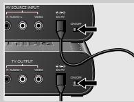
5 AV SOURCE INPUT connectors
For connecting the transmitter to the PC via the TV-Out output of your video card and the 3.5 mm stereo jack of your sound card (Audio Out).
VIDEO (yellow) - video input connector
R-AUDIO-L - left (L) and right (R) audio input connectors (R-red / L-white)
6 CHANNEL switch
Selects the desired frequency channel of the audio/video signal. The number of channels you can select may vary from country to country.
7 IR
Optional connector for (future) use, together with a PC with PC remote control functionality.
8 AC power adapter
9 RCA+ 3.5 mm jack to RCA audio/video cable (yellow/red/white to yellow/black)
For connecting the PC to the transmitter via the AV SOURCE INPUT connectors.
10 Audio splitter (3.5 mm jack)
For connecting the transmitter to the PC in case PC speakers are connected to the PC sound card.
B) Receiver unit
11 Power light
Lights green when power is switched on.
12 Remote control receiver light
Indication light for (future) use, together with a PC with PC remote control functionality.
13 ON/OFF switch
Switches the receiver unit on and off.
14 DC 9V ♦-G-
DC power supply socket for connection to the mains.
15 TV OUTPUT connectors
For connection the transmitter to an RCA or SCART enabled TV or stereo set.
VIDEO (yellow) - video output connector.
R-AUDIO-L - left (L) and right (R) audio output connectors
(R-red / L-white).
16 CHANNEL switch
Selects the desired frequency channel of the audio/video signal.
The number of channels you can select may vary per country.
17 AC Power adapter
18 RCA to RCA audio cable (red/white)
For connecting the receiver to audio inputs of the TV or audio equipment.
19 RCA to RCA video cable (yellow)
For connecting the receiver to the video inputs of the TV via the TV OUTPUT connectors.
20 RCA to SCART adapter (not for U.S.A. version)
For connecting the receiver to the audio/video inputs of the TV in case the TV is equipped with a SCART connector.
8 ENGLISH
3. Installation
Setting up the transmitter unit
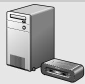
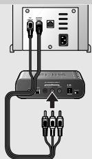
1 Position the transmitter unit near of the PC. Never place other devices on top of the transmitter unit.
2 Check the Instructions For Use of the PC sound card for the exact location of the audio output.
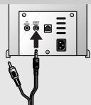
3 Connect the 3.5mm jack plug (black) of the audio/video cable (9) supplied to the audio output of the PC.
Please note that the rear of your PC may differ from the example in the illustration.
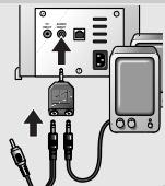
In case you have PC speakers connected to the PC
3a Remove the PC speaker plug from the audio output of the PC and connect it to the Audio splitter (10) supplied.
3b Connect the 3.5 mm jack plug (black) of the audio/video cable (9) supplied to the Audio splitter (10).
3c Connect the Audio splitter (10) to the audio output of the PC.
4 Connect the video plug (yellow) of the audio/video cable (9) supplied to the TV-Out output of the PC.
Read the Instructions For Use of the PC or video card on how to activate the TV-Out function. In case are not able to activate the TV-out of your video card, contact the helpdesk of the PC or videocard manufacturer
5 Connect the audio/video plugs at the other end of the audio/ video cable (9) supplied to the AV SOURCE INPUT connectors (5) on the transmitter unit.
Make sure to insert the yellow plug into the yellow video input and the white and red audio plugs into the left (L) and right (R) audio inputs.
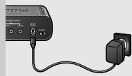
6 Connect the AC power adapter (8) to a mains socket and to the DC 9V -G - supply socket (4) of the transmitter unit.
Connecting the receiver unit to the TV
1 Position the receiver unit close to the TV.
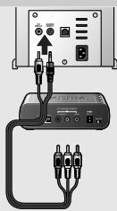
2 Connect the RCA to SCART adapter (20) supplied to the SCART connector of the TV.
3 Connect the video cable (19) and audio cable (18) supplied to both the adapter and the TV OUTPUT connectors (15) of the receiver.
Make sure to insert the yellow plugs into the yellow video in- and outputs and the red and white plugs into the red and white audio in- and outputs.
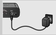
4 Connect the AC power adapter (17) to a mains socket and to the DC 9V -一 supply socket (14) of the receiver unit.
Note: In case your TV is equipped with RCA connectors you can directly connect the TV OUTPUT connectors (13) of the receiver to the corresponding RCA connectors of the TV. Make sure to insert the yellow, white and red plugs into the yellow, white and red inputs on both receiver and TV.
Channel selection
- Set the CHANNEL switches (6 and 16) on both units to channel 1.
- If interference occurs (e.g. degraded image) set both switches to another channel.
Both units are now ready for use.
Note: Both units must always be set to the same channel.
Optional connection to audio equipment
1 Connect one end of the video cable (19) supplied to the video input (yellow) of the SCART adapter (or directly to the yellow video input of the TV) and the other end to the VIDEO output (15) of the receiver.
2 Connect the audio cable (18) supplied to the AUX input of the audio equipment and the R-AUDIO-L outputs (15) of the receiver.
Make sure to insert the white and red plugs into the left (L) and right (R) inputs.
Read the Instructions For Use of the audio equipment for the correct input.
3 Connect the AC power adapter (17) to a mains socket and to the DC 9V -一 supply socket (14) of the receiver unit.
Audio information from the PC will now be heard via the audio equipment.
4 Play an audio file on the PC to check if the audio signal is available on the audio output.
4. Operation
1 Turn on the PC and select an audio or video file you want to play.
2 Start playback of the selected file. Refer to the Instructions For Use of your Windows operating system on how to select and play audio/video files.
3 Make sure you see the movie playing on your PC monitor or hear the music on the PC speakers, if connected.
4 Activate the TV-Out function of your PC video card and make sure you have video signal available on the TV-Out output. Refer to the Instructions For Use of your video card for details.
5 Turn on the TV.
6 Select the external input (EXT or AV) on your TV.
Read the Instructions For Use of your TV.
7 Set the ON/OFF switch on both transmitter (3) and receiver (13) to ON.
You can now watch the video source on your TV.
Notes:
- The Wireless PC-TV Link does NOT give you control over PC and/or audio/video content you are playing. You need to manually start/stop playing videos or audio songs on your PC via the connected mouse or keyboard.
- You should see the video you are playing on the PC on the TV screen, if not please check if you performed all steps correctly and make sure you have a video signal on the TV-out of your PC. If you have a TV-signal on the TV-out of your PC but no reception on the Reciever, refer to the troubleshooting section of this manual.
5. Problem solving
If a fault occurs, first check the points listed below. If you are unable to remedy a problem by following these hints, contact the helpline (see 'Need help?') or consult your dealer. Never try to open the set yourself as this will void the guarantee.
First, check all cables to ensure that they are connected correctly.
Problem
No picture on TV
- Turn on the PC and start playing a video file. Make sure the TV-Out output of the video card is activated and a video signal is present. Refer to the Instructions For Use of the video card on how to activate the TV-Out output of the video card.
- In case you have a portable TV you can check if a TV-out signal is present on your video card by transferring the TV to the PC and connect the TV-out directly to the TV.
Make sure both units are turned on (both green power lights (1 and 11) are lit). - Select the correct EXT or AV channel on TV. Refer to the Instructions For Use of the TV.
- Select the same channel on the receiver and transmitter units, using CHANNEL switches 6 and 16.
Bad picture/sound quality on TV
- Move the receiver unit around on the surface it is positioned on, centimetre by centimetre until you get good picture and sound quality.
- Carry out the same procedure for the transmitter unit.
- Change both units to another frequency channel, using CHANNEL switches 6 and 16.
Make sure that both units use the same frequency channel. - Reduce the distance between the transmitter and receiver units (less than 30 metres).
12 ENGLISH
Wrong picture on on TV
- Select the correct EXT or AV channel. Refer to the Instructions For Use of the TV.
- It is possible that a signal from another Wireless Link is being picked up. Switch to another channel on both units, using CHANNEL switches 6 and 16 to receive your own signal.
Make sure that the same channel is selected on both units!
Buzzing sound when using a remote control
- The buzzing sound could be caused by functionality implemented for future use. Move the transmitter unit around, centimetre by centimetre, until the buzzing sound disappears. In some cases you will not be able to overcome this problem.
- Move the transmitter unit around, centimetre by centimetre, until the buzzing sound disappears. In some cases you will not be able to overcome this problem.
TV gives black & white pictures
- Make sure your TV-out signal is in CVBS or Composite format. Refer to Instructions for use of your video card for details.
6. General notes
- Picture and sound quality is influenced by the use of microwave ovens. Other wireless systems (Bluetooth, wireless LANs, etc.) can also adversely influence the quality of picture and sound, and vice versa.
- The Wireless PC-TV Link is a Radio Frequency (RF) based product. As such its performance can suffer the same kinds of interference as GSMs, portable radios and other RF-based products.
- The Wireless PC-TV Link is not limited to just one room or house. You can use it anywhere in or around the house. Consequently, anybody in the vicinity of your house (up to the maximum operating range) who also owns a Wireless Link set to the same channel, can watch the same programmes that are playing on your video source.
- PC cannot be controlled remotely if the carrier frequency of the IR signal is outside the operation window of 32kHz to 40kHz . This infrastructure functionality is part of future functionality.
- Radio wave safety: When switched on, the Philips Wireless PC-TV Link transmits and receives radio waves. The Philips Wireless PC-TV Link complies with the standards that are defined for it.
-
The Philips Wireless PC-TV Link has an operating range of up to 100 metres in open air. Walls, ceilings and other large objects may limit the useable operating range up to 30 metres in the house.
-
Technical specifications
| General | Video standards supported | PAL / NTSC / SECAM |
| Power supply | 220 - 240V AC / 50Hz | |
| Operating consumption: | 3 W (both transmitter and receiver unit) | |
| Transmitter unit | Audio input: | Stereo audio (white/red RCA connectors) |
| Video input: | CVBS (yellow RCA connector) | |
| Dimensions | 14.3 cm (W) x 9.3 cm (D) x 4 cm (H) | |
| Receiver unit | Output (audio/video) | Stereo audio (white/red RCA connectors) |
| Operating range | CVBS (yellow RCA connector) | |
| Dimensions | Up to 100 metres in open air; up to 30 metres indoors | |
| Carrier frequency: | 2.4 GHz | |
| Number of channels: | four (may differ, depending on local regulations) | |
| Type of modulation: | FM | |
| Transmission power: | <10mW | |
| Antennas: | Built-in | |
| Audio / Video transmission | Carrier frequency: | 433.92 MHz |
| Type of modulation: | AM | |
| Transmission power: | <10 mW | |
| Range of IR reception: | Up to 5 metres | |
| Carrier frequency range | 32 kHz – 40 kHz | |
| Remote control blaster cord: | Yes, one infrared light |
Need Help?
In case you have any questions about the LM1000, please contact our helpline for assistance! You can find the number in the list on page 2.
Before you call, please read this manual carefully.
You will be able to solve most of your problems.
The model number of the Wireless PC-TV Link is LM1000.
Date of purchase: //
day /month /year
14 FRANÇAIS
5 AV SOURCE INPUT Anschlüsse
15 TV OUTPUT Anschlüsse
Imagens a preto e branco no television
- Verifique se o sinal TV-out está no formato CVBS ou Composto.
PpOaIaEiIaOaIaIaIaIa
DECLARATION OF CONFORMITY
We, Philips Consumer Electronics, Peripherals & Accessories: Building SBP6
(manufacturer's name)
P.O.Box 80002, 5600 JB Eindhoven, The Netherlands
(manufacturer's address)
declare under our responsibility that the radio product:
Philips
(name)
SBC LM1000 -/00, -/05, (Tx: SBC LM1002/00; Rx: LM1005/00)
(type or model)
RF Video Link System
product description)
to which this declaration relates is in conformity with the following standards:
EN 300 440 part 1&2, (2001-9).
EN 300 220 part1 & 2 (2000-9)
ETS 301 489 part 1&3 (2000-8)
EN 60950:2000
(title and/or number and date of issue of the standards)
following the provisions of 1999/5/EC (R&TTE Directive)
and is produced by a manufacturing organisation on ISO 9000 level.

Eindhoven, 04/02/2004
(place, date)
K.Rysman
Approbation manager
(signature, name and function)
AQ95-56F-524-PF
REPORT No.)
DECLARATION OF CONFORMITY
We, Philips Consumer Electronics, Peripherals & Accessories: Building SBP6
(manufacturer's name)
P.O.Box 80002,5600 JB Eindhoven, The Netherlands
(manufacturer's address)
declare under our responsibility that the radio product:
Philips
(name)
SBC LM1000 -/16, (Tx: SBC LM1002/16; Rx: LM1005/16)
(type or model)
RF Video Link System
product description)
to which this declaration relates is in conformity with the following standards:
EN 300 440 part 1&2, (2001-9).
EN 300 220 part1 & 2 (2000-9)
ETS 301 489 part 1& 3 (2000-8)
EN 60950:2000
(title and/or number and date of issue of the standards)
following the provisions of 1999/5/EC (R&TTE Directive) and is produced by a manufacturing organisation on ISO 9000 level.
Eindhoven, 04/02/2004
(place, date)
K.Rysman
Approbation manager
(signature, name and function)
Guaranteee certificate
Garantiebewijs
Certificado de garantia
Garantibevis
Certificat de garantie
Certificado de garantia
Eyyunon
Garantibevis
Garantieschein
Certificato di garanzia
Garanticertifikat
Takuutodistus

year warranty
année garantie
Jahr Garantie
jaar garantie
aano garantia
anno garanzia
xovoc ar garanti
ar garanti
ar garanti
vuosi takuu
ano garantia
Type: SBC LM1100
Serial nr:
Date of purchase - Date de la vente - Verkaufsdatum - Aankoopdatum - Fecha de compra - Date d'acquisito - Data da adquirência - Hερογίαν αγρός - Inkops datum - Anskaffesesdata - Kjøpedato - Oatopävä -
Dealer's name, address and signature
Nom, adresse et signature du revendeur
Name, Anschrift und Unterschrift des Handlers
Naam, adres en handtekening v.d. handelaar
Nombre, direction y firma del distribuctor
Nome, indirizzo e firma del fornitore
6 month guarantee on rechargeable batteries
6 mois de garantie sur les piles rechargeables
6 meses de garantia para las pilas recargables
6 Monate Garantie auf wiederaufladbare Batti
6 maanden garantie op oplaadbare batterijen
Garanzia di 6 messi sulle batterie ricaracibili
Ovoatae wmo, dieuovon kal uoypntou ept. npnent Aterforsaljarens namn, adress och signatur Forhandlers navn, adresse og underskrift Forhandlers navn, adresse og underskrift Jalleenmyyjan nimi, osoite ja allekirjoitus Nome, morada e assinature da loja
Pilhas recarregáveis com 6征求意见 of six degrees of guarantia
Eyyunon 6 mnuwov oε επανφορτιόμενες μηαταρίες
6 manaders garanti pā laddningsbateriier
6 manedes garanti pā genopladelige batterier
6 manedes garanti pā de oppladbare batteriene
Ladattavilla akulla on 6 kuukaarden takuu
www.philips.com
This document is printed on chlorine free produced paper
Data subject to change without notice
Printed in China
C∈0682①

- ENGLISH
- Wireless PC-TV Link
- SBC LM1000
- Contents
- Important information
- Safety precautions
- Packaging contents
- ENGLISH
- Functional overview
- A) Transmitter unit
- Power light
- Remote control receiver light
- ON/OFF switch
- DC 9V -C-
- AV SOURCE INPUT connectors
- CHANNEL switch
- IR
- AC power adapter
- RCA+ 3.5 mm jack to RCA audio/video cable (yellow/red/white to yellow/black)
- Audio splitter (3.5 mm jack)
- B) Receiver unit
- Power light
- Remote control receiver light
- ON/OFF switch
- DC 9V ♦-G-
- TV OUTPUT connectors
- CHANNEL switch
- AC Power adapter
- RCA to RCA audio cable (red/white)
- RCA to RCA video cable (yellow)
- RCA to SCART adapter (not for U.S.A. version)
- ENGLISH
- Installation
- Setting up the transmitter unit
- In case you have PC speakers connected to the PC
- Connecting the receiver unit to the TV
- Channel selection
- Optional connection to audio equipment
- Operation
- Problem solving
- Problem
- No picture on TV
- Bad picture/sound quality on TV
- ENGLISH
- Wrong picture on on TV
- Buzzing sound when using a remote control
- TV gives black & white pictures
- General notes
- Need Help?
- FRANÇAIS
- AV SOURCE INPUT Anschlüsse
- TV OUTPUT Anschlüsse
- Imagens a preto e branco no television
- PpOaIaEiIaOaIaIaIaIa
- DECLARATION OF CONFORMITY
Brand : PHILIPS
Model : SBCLM1000
Category : Bluetooth speaker