
SBCLI900 - Bluetooth speaker PHILIPS - Free user manual and instructions
Find the device manual for free SBCLI900 PHILIPS in PDF.

| Product type | Portable Bluetooth speaker |
| Brand | Philips |
| Model | SBCLI900 |
| Dimensions (W x D x H) | Approx. 150 x 60 x 60 mm |
| Weight | Approx. 300 g |
| Power supply | Rechargeable lithium-ion battery (via micro-USB cable) |
| Battery life | Up to 8 hours (depending on volume) |
| Connectivity | Bluetooth 4.0 or higher |
| Bluetooth range | Up to 10 meters |
| Speakers | 1 full-range speaker |
| Output power | 3 W RMS |
| Built-in microphone | Yes, for hands-free calls |
| Functions | Wireless audio playback, volume control, call management |
| Auxiliary input | Yes, 3.5 mm jack |
| LED indicator | Battery and connection status |
| Care and cleaning | Wipe with a soft, dry cloth. Do not use abrasive products. |
| Safety | Do not expose to water or humidity. Do not open the device. |
| Spare parts and repairability | Battery replaceable by a professional. Standard micro-USB cable. |
| General information | Indoor use. Operating temperature: 0°C to 40°C. |
Frequently Asked Questions - SBCLI900 PHILIPS
User questions about SBCLI900 PHILIPS
0 question about this device. Answer the ones you know or ask your own.
Ask a new question about this device
Download the instructions for your Bluetooth speaker in PDF format for free! Find your manual SBCLI900 - PHILIPS and take your electronic device back in hand. On this page are published all the documents necessary for the use of your device. SBCLI900 by PHILIPS.
USER MANUAL SBCLI900 PHILIPS
RF Extender-User guide Prolongateur de signal RF-Mode d'emploi HF Extender-Benutzeranleitung Extensor de RF-Guía del usuario RF-signaaluitbreider-Gebruiksaanwijzing
English 4
Français 13
Deutsch....22
Español 31
Nederlands....40
User Guide
Helpline
European regulations
This product has been designed, tested and manufactured according to the European R&TTE directive 1999/5/EC. Following this Directive, this product can be brought into service in the following countries:
SBC LI 900/00
R&TTE Directive 1999/5/EC
| BE √ | DK √ | GR √ | ES √ | FR √ |
| IRE ✘ | IT √ | LU √ | NL √ | AT √ |
| PT √ | FI √ | SE √ | UK ✘ | NO √ |
| DE √ | CH √ |
Nederland
053 4849106
Norge 2270 8258
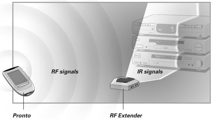
Note: In this user guide Pronto is used for both ProntoPro and Pronto remote controls. LI900 is compatible with RU950 and RU970.
About the LI900
Most remote control systems have to be operated by pointing the remote control directly towards a device. Any obstacle between the remote control and the device disturbs the operating signal. But what if you like to place your devices inside a closed cabinet, a closet or even in another room?
The LI900 provides the solution to overcome obstacles like furniture or walls. Your devices no longer have to be placed in line of sight but can be operated from virtually any location. The LI900 is a RF Extender that is used in combination with the Pronto Remote Control. The RF Extender receives radio frequency (RF) signals sent out by the Pronto and converts them into infrared (IR) signals. These IR signals are then sent out to your TV, DVD, preamplifier and so on.
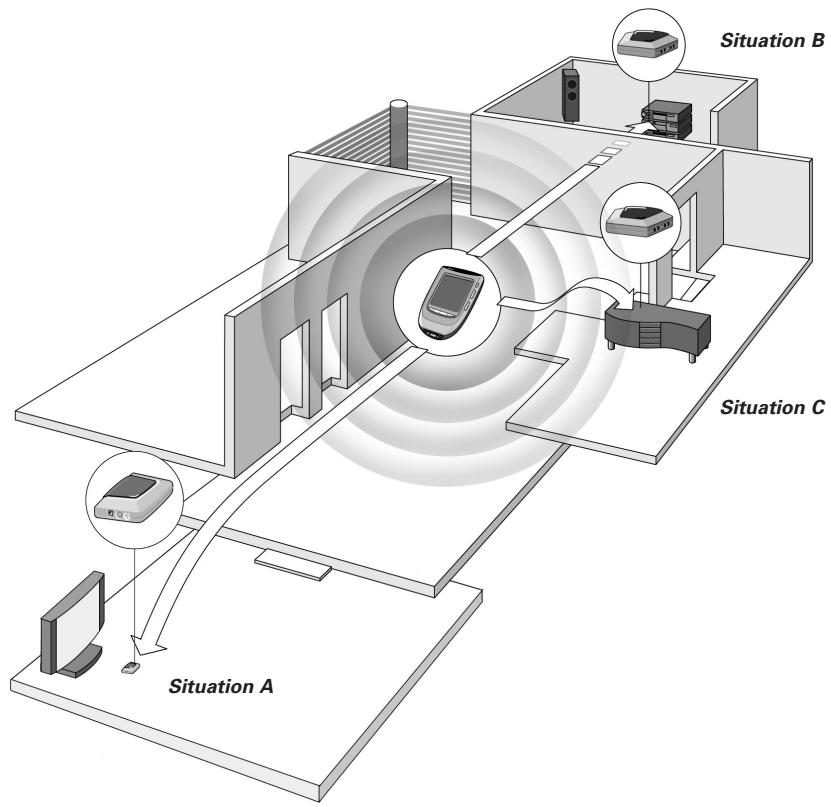
Possible Set-ups
The RF Extender can be used in several situations:
- Your devices can be remotely controlled while the RF Extender is placed in line of sight (situation A).
- The RF Extender controls devices placed in an adjacent room (situation B).
- The RF Extender is placed inside a closet, a rack or another piece of furniture together with your devices (situation C).
- The set-ups in situation A, B and C can be combined. If you want to control devices in different locations, you have to place a RF Extender in each location. You can control all RF Extenders with the same Pronto Remote Control. See Multiple RF Extenders on p. 9 to apply the necessary settings.
flowchart
graph TD
    A["Situation A"] --> B["Situation B"]
    B --> C["Situation C"]
    C --> D["Mobile Device"]
    D --> E["Computer"]
    style A fill:#f9f,stroke:#333
    style B fill:#ccf,stroke:#333
    style C fill:#cfc,stroke:#333
    style D fill:#fcc,stroke:#333
    style E fill:#ffc,stroke:#333
Installation
The following components should be present: RF Extender, power adapter, 4 dual IR emitters, mounting plate and 4 screws.
Before you install the RF Extender, you should decide which of the set-ups described on p. 5 apply to your needs. It is recommended to read through the entire User Guide.
Working Angle and Range of the IR blaster
Warning The IR signals sent out by the RF Extender always have to be able to reach the receiving eyes of your devices. Make sure that the IR blaster (dark plastic window on top of the RF Extender) is aimed at your devices.
To get optimal results, it is recommended to place the RF Extender horizontally with the IR blaster facing up or down.
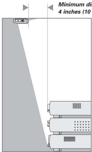
Figure 1: IR blaster facing down
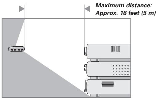
Figure 2: IR blaster facing up
Figure 1 represents the RF Extender mounted up side down inside a closet. Always maintain a minimum distance of 4 inches (10 cm) between the RF Extender and your devices.
Figure 2 represents the RF Extender with the IR blaster facing up. The RF Extender can be placed at a distance and higher than your devices. Make sure there are no objects between the RF Extender and the receiving eyes of the devices.
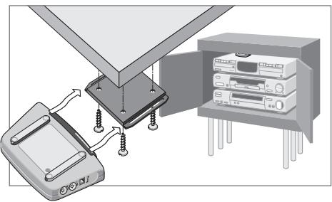
Mounting
The RF Extender can be mounted to a piece of furniture using the included mounting plate and the 4 screws. Take into account the range and the working angle of the IR blaster as explained on p. 6. Also make sure to place the RF Extender in a central position aimed directly at your devices.
Warning It is advised not to place the RF Extender inside or near a metal closet as RF signals can be disturbed by metal objects.
natural_image
Diagram showing a device connected to a server rack and an open storage unit (no text or symbols visible)1 Remove the mounting plate from the bottom of the RF Extender.
2 Screw the plate to a rack, closet or another piece of furniture. Provide sufficient space to connect the power adapter and to slide the RF Extender back on.
Note Depending on the surface, it may be possible to attach the RF Extender to the furniture using a piece of 2-sided tape. Look for the right position and make sure there is sufficient space.
3 Slide the RF Extender on the mounting plate.
Using the Dual IR Emitters
Like the IR blaster of the RF Extender, the dual IR emitters send out IR signals. You can use the dual IR emitters as an alternative for the IR blaster.
When to use the emitters
The IR emitters can control devices the IR blaster cannot reach, for instance when there is limited space around the receiving eyes of the devices, e.g. in a small closet.
Note The IR emitters can also be used in combination with the IR blaster of the RF Extender. Both send out IR signals simultaneously. This allows you to operate several devices using both the IR blaster and the IR emitters.
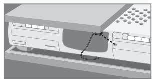
How to use the emitters
The dual IR emitters can be attached to the surrounding surface facing the receiving eyes or directly to the receiving eyes.
1 Attach the emitters to a surface above, below or in front of the receiving eyes of your devices (for aesthetic appearance or when it is difficult to locate the receiving eye). - or - Attach the emitters directly to the receiving eyes of your devices.
natural_image
Illustration of a computer monitor with a cable inserted into the screen (no text or symbols visible)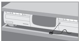
natural_image
Diagram of a car charging into a charging station with a cable, no text or symbols present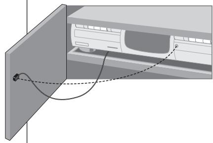
natural_image
Diagram of a car air conditioner unit with wiring and connection points (no text or symbols)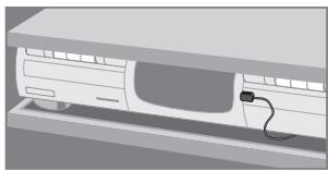
natural_image
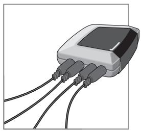
Illustration of a car interior with a cable inserted, no text or symbols present2 Plug the dual IR emitters into the RF Extender.
Note To avoid interference, the wires of the emitters should be kept away from the RF Extender as far as possible.
natural_image
Illustration of a connected electronic device with three cables (no text or symbols visible)User Guide
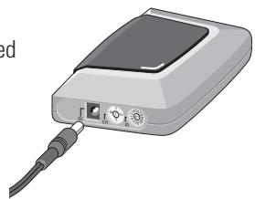
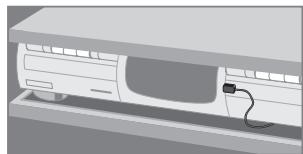
Connecting the Power Adapter
When connecting the power adapter it is recommended that you plug the adapter into the RF Extender before you plug it into the socket. When connected you will see a red LED on the RF Extender.
natural_image
Illustration of a portable electronic device with cables and ports (no text or symbols visible)Note To avoid interference, the adapter cable should be kept away from the RF Extender as far as possible.
Settings
As the RF Extender ‘communicates’ with the Pronto Remote Control, you have to set the same Extender ID (identity) on both appliances. The settings depend on whether you have a single RF Extender or multiple RF Extenders.
Single RF Extender
When you use only one RF Extender, you can accept the default setting for the Extender ID (ID=0). Make sure your Pronto Remote Control is set to the same default setting (see the Pronto User Guide for more details).
Multiple RF Extenders
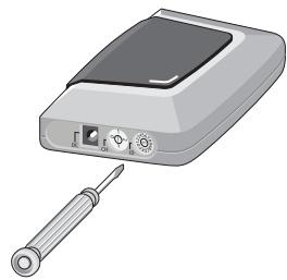
If you want to operate several of your devices independently, e.g. grouped on different locations, you will need multiple RF Extenders. When using several RF Extenders, it is important to assign a unique Extender ID to each RF Extender. 16 Extender IDs (from 0 to 9 and from A to F) can be assigned.
1 Choose an Extender ID for the RF Extender by turning the ID dial with a small screwdriver.
2 On the Pronto Remote Control, choose the same Extender ID for each device controlled by the RF Extender.
Refer to the Pronto User Guide for more information.
3 Try to operate your devices with the Pronto Remote Control.
The red LED will blink when the RF Extender receives a correct command.
4 Repeat this procedure for every RF Extender.
natural_image
Illustration of a handheld electronic device with a screwdriver inserted (no text or symbols visible)User Guide
RF Interference
If your devices are not responding to commands or if the red LED on the IR blaster is blinking without sending commands, it might be possible that there is RF interference. This can be the case when other RF appliances are operated nearby, for instance at your neighbours.
When you notice RF interference, you have to choose another channel on your RF Extender. 4 channels (CH from 0 to 3) can be assigned.
1 Choose a channel for the RF Extender by turning the CH dial with a small screwdriver.
2 On the Pronto Remote Control, choose the same channel for the devices controlled by the RF Extender.
Refer to the Pronto guide for more information.
3 Try to operate your devices with the Remote Control.
Troubleshooting
Devices do not respond properly
- Check if the power adapter is connected and the red LED is on.
- Check if the ID and channel numbers on the RF Extender match with the ID and channel numbers on the Pronto Remote Control (see p. 9). Refer to the Pronto User Guide for more details on the settings of the Remote Control.
- Check the placement of the RF Extender:
- Check the distance between the RF Extender and the Pronto Remote Control (see p. 6).
- Check the range and the working angle of the IR blaster (see p. 6).
- Check if the RF Extender is placed in a central position relative to your devices (see p. 7).
- Make sure that the distance between the RF Extender and your device is at least 4 inches (10 cm).
- Make sure that the distance between the RF Extender and your device is at most 16 feet (5 m).
- Make sure the IR signals between the RF Extender and the receiving eyes of your devices are not disturbed by any objects.
- Check if metal objects, for instance a metal closet, wires or cables, surrounding the RF Extender do not disturb the RF signals.
- If you are using the dual IR emitters, make sure they are connected properly and that they are placed within range of the receiving eyes (see p. 8).
- It might be possible that some commands cannot be sent out as RF signals. In that case you will have to reconfigure the Pronto Remote Control to operate your devices with IR signals again.
The red LED on the RF Extender blinks without using the Pronto Remote Control
- This indicates RF interference. Another device in the proximity is sending out RF signals. Change the channel (CH) on the RF Extender (see p. 10).
There is no red LED on my RF Extender
- Check if the power adapter is connected properly.
The dual IR emitters are no longer adhesive
- Replace the adhesive with a fresh piece of the 2-sided tape.
I cannot find the exact location of the device's receiving eye
- Check the manual of the device. When still in doubt, contact your supplier or the manufacturer.
Specifications
The specifications and design of this product are subject to change without notice.
| Hardware | Red LED (continuously on when powered, blinking during RF reception)16 IDs and 4 CHs4 outputs for IR emittersPossibility to have multiple RF extenders in one home not interferingPositioning: freestanding, mounted horizontally or hanging up side down |
| Dimensions | 4.5 x 3.2 x 1.2 inch (113 x 81 x 30 mm) |
| Operating temperature | 0°C to 50°C |
| Infrared (IR) | Operating distance: up to 16 feet (5 meters)IR frequency range: DC/flash codes, 36kHz-550kHz |
| Radio frequency (RF) | Operating distance: up to 100 feet (30 meters)depending on the surrounding conditionsFrequency: 433.92 MHz (Europe) |
| Dual IR emitters | Number of IR emitters: up to 8 (4x2), emitters wired in series3.5 mm mono mini-plugCable length: 10 feet (2.5 meters)Max. range: 3 feet (75 cm) |
| Accessories | 230V AC Power adapter (400mA/240V AC adapter, for UK) |
User Guide
Introduction
Installations possibles
natural_image
Diagram showing a device connected to a panel assembly with connectors and a server rack (no text or symbols visible)natural_image
Diagram of a computer monitor with an attached cable and indicator lights (no text or symbols)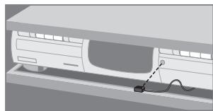
natural_image
Illustration of a car charging into a bus with a cable inserted (no text or symbols)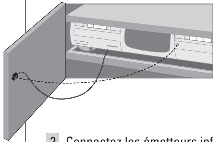
natural_image
Illustration of a washing machine with a cable inserted into the side panel (no text or symbols visible)natural_image
Illustration of a connected electronic device with three cables (no text or symbols visible)natural_image
Illustration of a gray electronic device with a cable and connector, no text or symbols visibleRemarque
natural_image
Illustration of a handheld electronic device with screwdriver and indicator lights (no text or symbols)natural_image
Diagram of a device assembly with a monitor, battery, and server unit (no text or symbols visible)natural_image
Illustration of a mechanical device with a cable inserted into a housing (no text or symbols visible)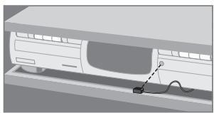
natural_image
Diagram of a car inside a vehicle showing a cable being inserted into the seat (no text or symbols present)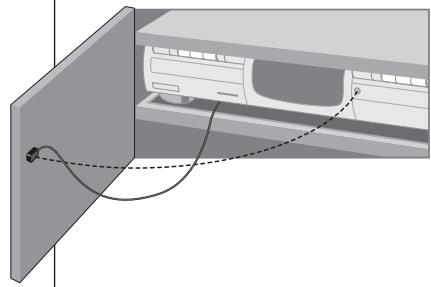
natural_image
Diagram of a car air conditioner unit with wiring and fan (no text or symbols)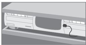
natural_image
Illustration of a vehicle chassis with a cable inserted, no text or symbols presentnatural_image
Illustration of a connected electronic device with three cables (no text or symbols visible)Benutzeranleitung
natural_image
Illustration of a portable electronic device with cable and ports (no text or symbols)natural_image
Illustration of a handheld electronic device with a screwdriver inserted (no text or symbols visible)natural_image
Diagram showing a device with screws inserted into a base, next to an open server rack (no text or symbols visible)natural_image
Diagram of a device with a cable inserted into a housing (no text or symbols visible)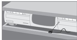
natural_image
Illustration of a car charging into a charging station with a cable (no text or symbols)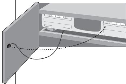
natural_image
Diagram of a washing machine with attached cable and fan (no text or symbols)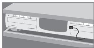
natural_image
Illustration of a car inside a vehicle chassis with a cable inserted (no text or symbols)natural_image
Illustration of a gray electronic device with a cable and connector, no text or symbols visiblenatural_image
Illustration of a handheld electronic device with a screwdriver inserted (no text or symbols visible)RF Interference
natural_image
Diagram showing a device connected to a server rack and an open storage unit (no text or symbols visible)natural_image
Illustration of a computer monitor with a cable inserted into the screen (no text or symbols visible)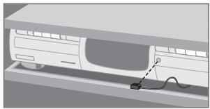
natural_image
Illustration of a car charging into a charging station with a power cord (no text or symbols)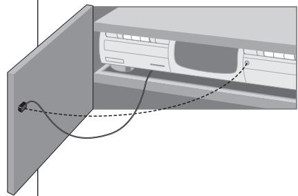
natural_image
Diagram of a computer monitor with cable routing and connection points (no text or symbols)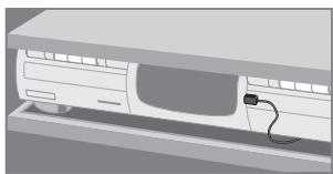
natural_image
Illustration of a car front panel with a cable inserted (no text or symbols)natural_image
Illustration of a connected electronic device with three cables (no text or symbols visible)Gebruiksaanwijzing
natural_image
Illustration of a portable electronic device with cables and ports (no text or symbols)Opmerking
natural_image
Illustration of a handheld electronic device with a screwdriver inserted (no text or symbols visible)Gebruiksaanwijzing
RF-interferentie
This document is printed on chlorine free produced paper Data subject to change without notice Printed in China
CE0682①
