
SBCLI910 - Bluetooth speaker PHILIPS - Free user manual and instructions
Find the device manual for free SBCLI910 PHILIPS in PDF.

User questions about SBCLI910 PHILIPS
0 question about this device. Answer the ones you know or ask your own.
Ask a new question about this device
Download the instructions for your Bluetooth speaker in PDF format for free! Find your manual SBCLI910 - PHILIPS and take your electronic device back in hand. On this page are published all the documents necessary for the use of your device. SBCLI910 by PHILIPS.
USER MANUAL SBCLI910 PHILIPS
natural_image
Two Philips Pento devices, one with antenna and one with earphone (no visible text or symbols on device body)User Guide
Gu'a del usuario
Mode dêmploi
RF Extender User Guide
User Guide RF Extender
© 2005 Royal Philips Electronics NV
Remark:
All rights are reserved. Reproduction in whole or in part is prohibited without prior consent of the copyright owner.
Royal Philips Electronics is not liable for omissions or for technical or editorial errors in this manual or for damages directly or indirectly resulting from the use of the RFX6500 / SBC LI910 RF Extender.
The information in this user guide may be subject to change without prior notice. All brand or product names are trademarks or registered trademarks of their respective companies or organizations.
Contents 2
How to Use the RF Extender 3
Introduction 3
How to Install the RF Extender 5
How to Connect the RF Extender 5
How to Position the Blaster Unit 6
How to Install the Dual IR Emitters 7
How to Position the Receiver Unit 9
How to Do More 12
How to Set the Extender IDs 12
How to Avoid Interference from Other Prontos 13
How to Use a Longer Connection Cable 13
How to Fine-Tune the Installation Using the Dip Switches 14
How to Turn Off the IR Blaster 14
How to Set the Dual IR Emitter Power Levels 14
Troubleshooting 16
Specifications 17
Introduction
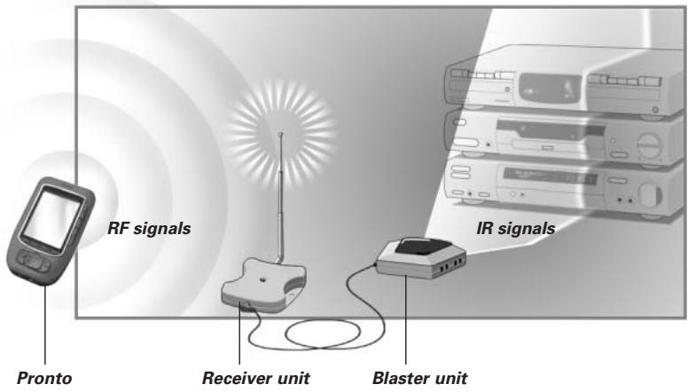
Infrared (IR) remote controls do not work properly when obstacles between the remote control and the audio/video devices disturb the operating signal. This problem can be solved using radio frequency (RF) as a carrier for IR commands. The Pronto Remote Control, in combination with the RF Extender, can operate audio/video devices from virtually any location.
The RF Extender consists of two units: a Receiver unit, and a Blaster unit. The Receiver unit receives RF signals sent out by the Pronto Remote Control. This unit is connected to the Blaster unit, which converts the signals into IR signals. The Blaster unit then transmits the IR signals to the audio/video devices.
When the Blaster unit cannot reach all devices or transmits with too much power, you can use the included Dual IR emitters. You can set up the Dual IR emitters in two ways:
■ The Dual IR emitters in combination with the Blaster unit.
When there is limited space around the IR receivers of the devices, for instance in a small closet.
■ The Dual IR emitters instead of the Blaster unit.
When you want to transmit IR signals very accurately, you turn off the Blaster unit, and control the devices by using the Dual IR emitters alone.
The arrangements in the situation shown above can also be combined. You can control all RF Extenders individually with one or more Pronto Remote Controls.
Make sure you have the following components: RF Extender Receiver unit, RF Extender Blaster unit, power adapter, connection cable, Dual IR emitters and screws.
The installation of the RF Extender consists of 4 main steps:
■ Connecting the RF Extender;
■ Positioning the Blaster unit;
■ Installing the Dual IR emitters;
■ Positioning the Receiver unit.
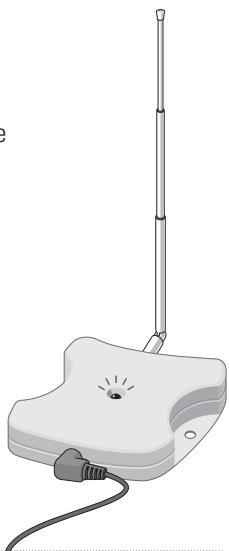
How to Connect the RF Extender
1 Plug the power cable into the Blaster unit.
2 Plug the power adapter into the mains wall socket. When connected, a red LED on the Blaster unit will start blinking. After a few seconds, the LED will stop blinking and stay on.
Remark The LED on the Blaster unit will also blink when the Blaster unit sends out IR signals to the audio/video devices.
3 Plug the connection cable into the Blaster unit until it clicks.
4 Plug the connection cable into the Receiver unit until it clicks. When connected, the LED on the Receiver unit will stay on for 3 seconds. Afterwards, the LED will go off.
natural_image
Illustration of a handheld electronic device with attached cables and a separate antenna, showing no text or symbols.How to Position the Blaster Unit
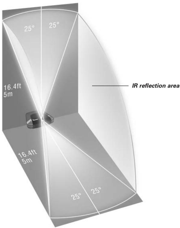
For optimal results, the Blaster unit should be positioned horizontally, either facing up, or facing down.
Make sure to place the Blaster unit in a central position aimed directly at the audio/video devices. The IR blaster (the dark plastic window on top of the Blaster unit) in particular should be aimed at the devices, since the IR signals sent out by the IR blaster must reach the IR receivers of the devices.
For optimal IR reception, position the Blaster unit so the devices are located within the working range of the Blaster unit, as shown in the picture below.
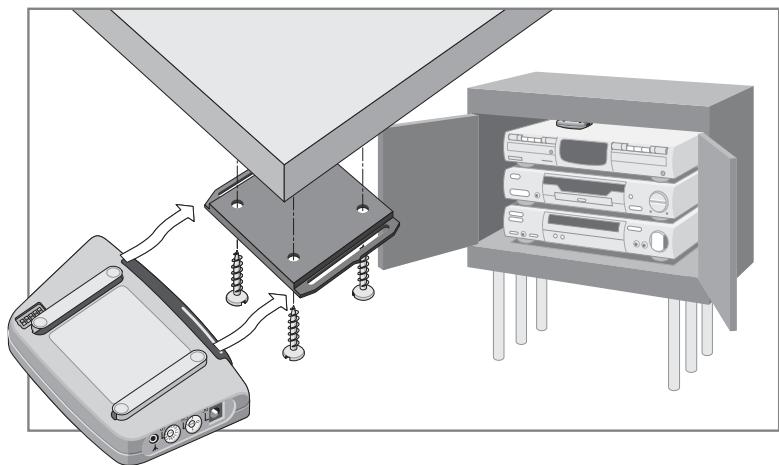
Once you have found the best position, you can optionally mount the Blaster unit onto a piece of furniture using the mounting plate and screws, which are included.
natural_image
Diagram showing a device with screws inserted into a panel, next to an open computer cabinet (no text or symbols visible)1 Screw the mounting plate to a rack, closet or another piece of furniture.
Provide sufficient space to connect the power adapter and to slide the Blaster unit back on.
Note Depending on the surface, it may be possible to attach the mounting plate to the furniture using a piece of 2-sided tape or velcro.
2 Slide the Blaster unit onto the mounting plate.
How to Install the Dual IR Emitters
The Dual IR emitters can be used in combination with, or as an alternative for the Blaster unit.
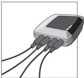
1 Plug the Dual IR emitters into the Blaster unit.
natural_image
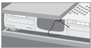
Illustration of a connected electronic device with three leads (no text or symbols visible)2 Attach the Dual IR emitters to a neighboring surface facing the IR receiver (for aesthetic purposes or when it is difficult to locate the IR receiver).
- OR -
Attach the Dual IR emitters directly to the IR receivers of the audio/video devices.
Make sure the Dual IR emitters are connected properly and that they are placed within range of the IR receivers.
natural_image
Diagram of a computer monitor with an attached cable and indicator lights (no text or symbols)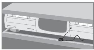
natural_image
Illustration of a car charging into a charging station with a cable (no text or symbols)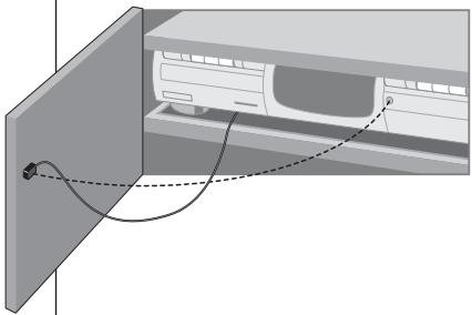
natural_image
Diagram of a car air conditioner unit with cooling panel and wiring (no text or symbols)
natural_image
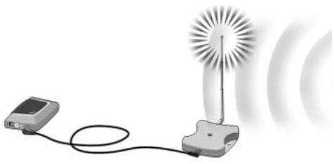
3D rendering of a white electronic device with a cable inserted into its side panel (no text or symbols visible)How to Position the Receiver Unit
For optimal performance, the Receiver unit should be placed in a location where there is little or no RF interference.
In most cases, however, you will notice no RF interference.
There may be RF interference when other appliances (such as WiFi base stations, audio/video devices, microwave ovens, or wireless telephones) are operated nearby.
The LED on the Receiver unit indicates the amount of RF interference.
The amount of RF interference present is indicated by the rate at which the LED blinks and the brightness of the LED when blinking (a higher rate of blinking and a brighter light means more RF interference).
To avoid interference, place the Receiver unit in a position in which the Receiver unit LED blinks and burns as little as possible.
natural_image
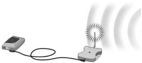
Illustration of a simple antenna device with a vertical pole and cable, no text or symbols present.Remark Do not operate the Pronto Remote Control while positioning the Receiver unit, since both RF interference and operation of the Pronto Remote Control will cause the LED of the Receiver unit to blink.
To find the position with the least amount of RF interference, try out the following steps:
1 Try to create the worst-case scenario, by turning on all devices that may cause RF interference. If the RF Extender and the Pronto Remote Control work properly in this scenario, they will certainly work in other situations.
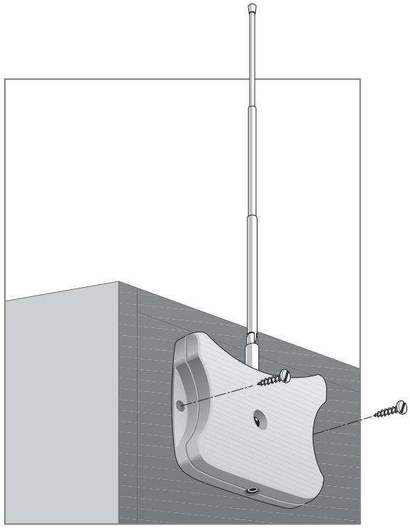
2 Extend the antenna of the Receiver unit, and direct it upwards.
natural_image
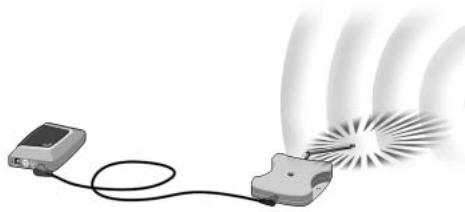
Illustration of a simple electric device connected to a light bulb with radiating waves (no text or symbols)3 Check the LED on the Receiver unit for RF interference.
If the LED does not blink, or blinks only sporadically, position the Receiver unit there, and continue with step 7. If the LED still blinks, continue with the next step.
Note When the LED blinks only sporadically, with low light intensity, there are no problems with RF interference.
4 Try out other positions moving the Receiver unit around, and check the LED for RF interference.
If the LED does not blink, or blinks only sporadically, mount the Receiver unit in that place, and continue with step 7. If the LED still blinks, continue with the next step.
Tip Do not position the Receiver unit:
Near audio/video devices, since these devices may cause RF interference. In particular, keep the Receiver unit away from optical audio/video devices, such as a DVD player.
- Near microwave ovens or wireless access points.
■ Inside a metal closet, since metal objects can disturb RF signals.
5 Retract the antenna, keeping it directed upwards.
Retracting in the antenna will cause the Receiver unit to be less sensitive to interference. It will also decrease the working range of the Pronto Remote Control.
natural_image
Illustration of a simple electrical device connected to a glowing light source with radiating waves (no text or symbols)6 Try out other positions moving the Receiver unit around, and check the LED for RF interference.
If the LED does not blink, or blinks only sporadically, mount the Receiver unit in that place.
7 Try out your Pronto Remote Control.
When sending commands with the Pronto Remote Control, the LEDs of both the Receiver unit and the Blaster unit should blink.
8 If necessary, aim the antenna in the direction where the Pronto Remote Control will be used, to improve the performance in that direction.
natural_image
Illustration of a device emitting a beam of light through a fan-like structure (no text or symbols)Once you have found the best position you can optionally mount the Receiver unit onto a piece of furniture using 2 screws.
natural_image
Technical illustration of a mechanical clamp or bracket assembly with a vertical pole and threaded base (no text or symbols)Tip Depending on the surface, it may be possible to attach the Receiver unit to the furniture using a piece of 2-sided tape or velcro. Find the right position and make sure there is sufficient space. When the cable for connecting the Receiver unit and the Blaster unit is too short, you can use a longer cable (see How to Use a Longer Connection Cable p. 13).
How to Set the Extender IDs
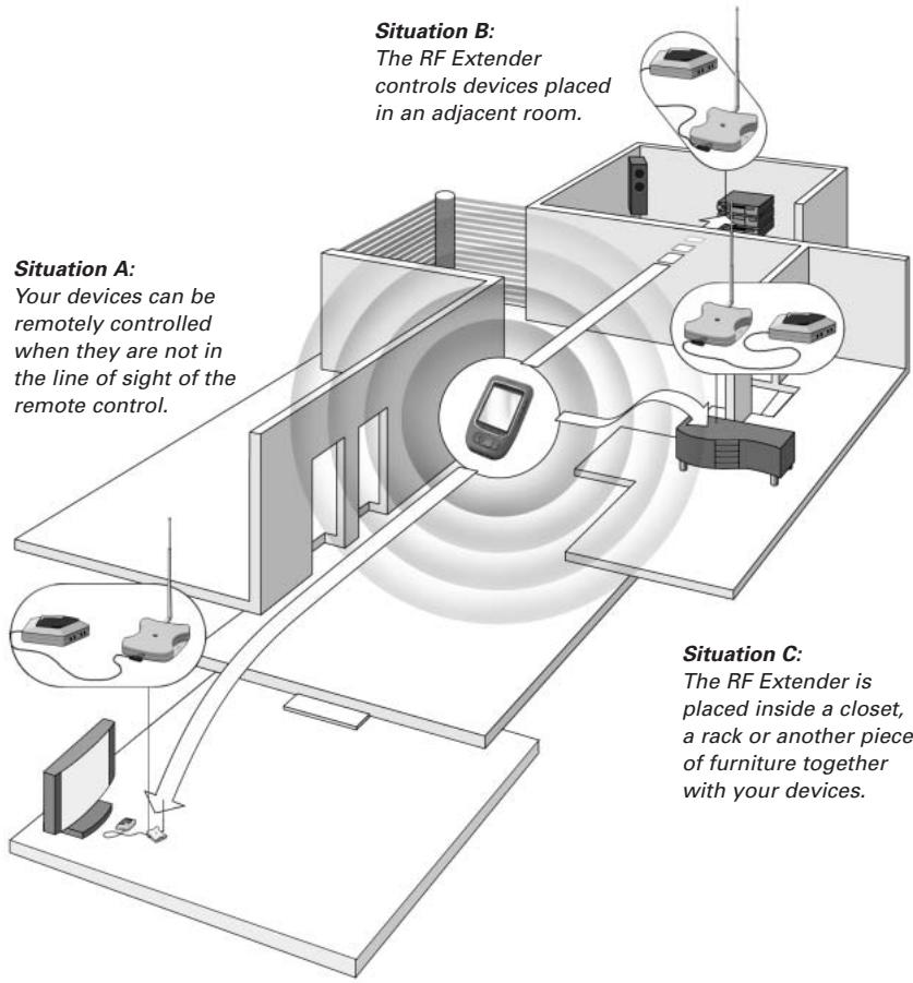
The RF Extender can be used in several situations as illustrated in the picture on p. 4: out of sight, in an adjacent room, or inside a closet.
Since the RF Extender ‘communicates’ with the Pronto Remote Control, you must set the same Extender ID (identity) on both appliances. The settings depend on whether you have a single RF Extender or multiple RF Extenders.
Single RF Extender
When you use only one RF Extender, you can accept the default setting for the Extender ID (ID=0).
On the Pronto Remote Control, choose the same Extender ID for each device controlled by the RF Extender.
Refer to the Pronto User Guide for more information.
Multiple RF Extenders
If you want to operate several of your devices independently, e.g. grouped in different locations, you need multiple RF Extenders. When using several RF Extenders, it is important to assign a unique Extender ID to each Blaster unit. You can assign 16 Extender IDs (from 0 to 9 and from A to F).
For the three RF Extenders in the picture on p. 4, you can set the Extender IDs as described below:
■ For situation A, set the Extender ID to 0;
■ For situation B, set the Extender ID to 1;
■ For situation C, set the Extender ID to 2.
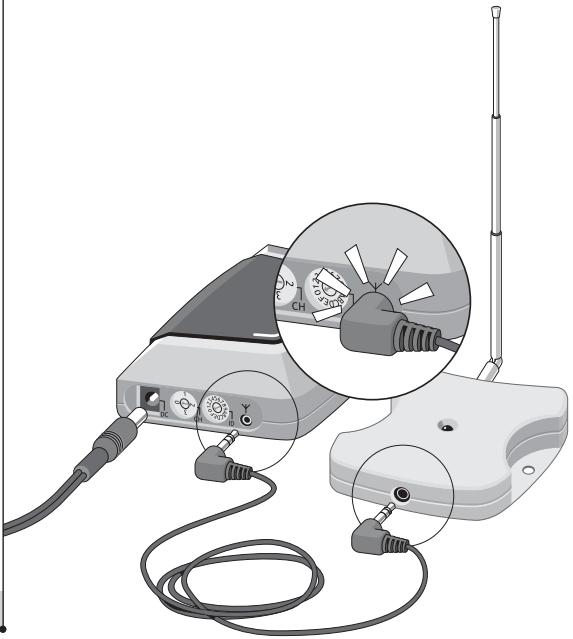
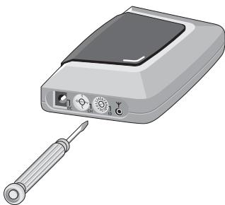
1 Choose an Extender ID for the Blaster unit by turning the ID dial with a small screwdriver.
natural_image
Illustration of a handheld electronic device with screwdriver and control panel (no text or symbols)2 On the Pronto Remote Control, choose the same Extender ID for each device controlled by the RF Extender.
Refer to the Pronto User Guide for more information.
3 Try to operate the devices with the Pronto Remote Control.
The red LED on the Blaster unit will blink when the RF Extender receives a correct command.
Note The LED of the Receiver unit will always blink when RF signals are being received, even when the extender ID of the Pronto Remote Control and the Extender ID of the blaster do not match.
The LED of the Blaster unit will blink only when the configuration of the Pronto Remote Control matches the Extender ID on the Blaster unit.
4 Repeat this procedure for every RF Extender.
How to Avoid Interference from Other Prontos
If the red LED on the Blaster unit is blinking without the Pronto Remote Control sending commands, the Receiver unit picks up signals from another Pronto Remote Control on the same channel. You can solve this problem by changing the channel.
You configure the channel on the Pronto Remote Control and on the Blaster unit. Both channels must be the same. Four channels (CH from 0 to 3) can be assigned.
1 Choose a channel on the Blaster unit by turning the CH dial with a small screwdriver.
2 On the Pronto Remote Control, choose the same channel. Refer to the Pronto manual for more information.
3 Try to operate your devices with the Remote Control.
How to Use a Longer Connection Cable
When the connection cable included is not long enough to connect the Receiver unit to the Blaster unit, you can use a longer cable (up to 20 ft / 6 m). You can connect the Receiver unit to the Blaster unit with a standard shielded stereo audio cable with 2.5 mm male jacks on both sides.
How to Fine-Tune the Installation Using the Dip Switches
At the bottom of the Blaster unit, you find 5 dip switches (numbered 1-5). When you use Dual IR emitters to send the IR signals to the audio/video devices, configure the dip switches to:
■ Turn the IR blaster on or off (independently from the Dual IR emitters);
- Configure the power levels of the Dual IR emitters, e.g.:
- When you configure the Dual IR emitters in wired IR solutions using a connecting block.
In this case, you can adjust the power levels of the Dual IR emitters.
- When you use a device that interferes with IR signals, such as a plasma TV set.
In this case, you can raise the power levels of the Dual IR emitters, since plasma technology might cause IR interference.
- When you want to operate 2 identical devices that are placed next to each other using 2 RF Extenders.
In this case, you can lower the power levels of the Dual IR emitters, in order to prevent the devices from receiving IR signals intended for another device.
| Switch | Switches 1 + 2 | Switches 3 + 4 | Switch 5 |
| Function | Dual IR emitters 1 - 2Power level | Dual IR emitters 3 - 4Power level | IR blasterOn/Off |
By default, all dip switches are set to 1 (On).
How to Turn Off the IR Blaster
When you decide to control the audio/video devices with Dual IR emitters only, you can turn off the IR blaster of the Blaster unit.
■ To turn off the IR blaster, set switch 5 to 0 (Off).
How to Set the Dual IR Emitter Power Levels
You can use dip switches 1 to 4 to set the power level of the Dual IR emitters. To set the power level:
■ For Dual IR emitters 1 and 2, use switches 1 and 2;
■ For Dual IR emitters 3 and 4, use switches 3 and 4.
You can choose between 4 power levels (0, 1, 2 and 3). By default, power level 3 is selected for each group of Dual IR emitters.
You can set the power level as indicated below:
| Power level(Operating distance) | Switch 1 | Switch 2 | Switch 3 | Switch 4 |
| 0 (0.7 m) | 0 (Off) | 0 (Off) | 0 (Off) | 0 (Off) |
| 1 (1.5 m) | 0 (Off) | 1 (On) | 0 (Off) | 1 (On) |
| 2 (2.0 m) | 1 (On) | 0 (Off) | 1 (On) | 0 (Off) |
| 3 (2.5 m - default setting) | 1 (On) | 1 (On) | 1 (On) | 1 (On) |
Remark The Dual IR emitters still send out IR signals when the power level is set to zero. The emission is never completely turned off.
The red LED on the Receiver unit blinks when the Pronto Remote Control is not being used
This indicates RF interference. See p. 9.
The red LED on the Blaster unit blinks when the Pronto Remote Control is not being used
This indicates that another Pronto Remote Control is being used in the proximity of the Receiver unit. See p. 13.
There is no red LED on my Blaster unit
■ Make sure the power adapter is connected properly. See p. 5.
The red LED on the Receiver unit does not blink when connecting it to the Blaster unit
■ Make sure the power adapter is connected properly to the Blaster unit. See p. 5.
■ Make sure the connection cable between the Receiver unit and the Blaster unit is connected properly. See p. 5.
The Dual IR emitters are no longer adhesive
- Replace the adhesive with a fresh piece of transparent 2-sided tape.
I cannot find the exact location of the device's IR receiver
- Set the Dual IR emitters to the minimal power level, and hold one of the emitters 0.4 - 0.8 inch / 1 - 2 cm in front of the device.
Move the emitter across the front panel, and take note of when the device reacts to the IR signals of the emitter.
When the device reacts, position the emitter in that place. - Check the manual for the device.
If you are still in doubt, contact your supplier or the manufacturer.
The specifications and design of this product are subject to change without notice.
| Hardware Blaster unit | Red LED (continuously on when powered, blinking during IR emission) |
| 16 IDs and 4 CHs | |
| 4 outputs for IR emitters | |
| Input for Receiver unit | |
| Possibility of having multiple RF extenders in one home not interfering | |
| Positioning: freestanding, mounted horizontally or hanging up side down | |
| Hardware Receiver unit | Red LED (blinking when receiving RF commands and RF interference) |
| Output for Blaster unit | |
| RF antenna | |
| Dimensions Blaster unit | 4.5 x 3.2 x 1.1 inch (112.9 x 81.2 x 26.8 mm) |
| Dimensions Receiver unit | 3.0 x 2.9 x 0.9 inch (77 x 73 x 23.5 mm) |
| Dimensions antenna | Extended: 0.7 inch (17.7 mm) |
| Retracted: 0.4 inch (9.7 mm) | |
| Fully rotatable (360°) | |
| Operating temperature | 32°F to 122°F (0°C to 50°C) |
| Infrared (IR) | Operating distance: 16.4 ft – 22.9 ft (5-7 meters) |
| IR frequency range: DC/flash codes, 25kHz-100kHz | |
| Radio Frequency (RF) | Operating distance: 147.6 ft (45 m) outdoor |
| Dual IR emitters | Number of IR emitters : up to 8 (4x2), emitters wired in series |
| 3.5 mm mono mini-plug | |
| Cable length: 10 ft (2.5 meters) | |
| Min. range: 3 ft (75 cm) | |
| Power adapter | RFX 6500: 120V / 60 Hz AC Power adapter (400mA/12V DC adapter, UL-approved) |
| SBC LI910: 230V / 50 Hz AC Power adapter (400mA/12V DC adapter, CE-approved) | |
| Accessories | Connection cable (standard shielded stereo audio cable, 2.5 mm male jacks on both sides, up to 20 ft / 6 m) |
| Dual IR emitters | |
| Power adapter | |
| Mounting kit (Plate and screws) |
natural_image
Diagram showing a device with screws inserted into a panel, next to an open server rack (no text or symbols present)natural_image
Illustration of a connected electronic device with three cables (no text or symbols visible)natural_image
Illustration of a wireless antenna with a vertical pole and cable, no text or symbols presentObservaciones
natural_image
Illustration of a wireless device with a sun source and connected cable, emitting sound waves (no text or symbols)natural_image
Illustration of a device connected to a speaker with a radiating light source, emitting sound waves (no text or symbols)natural_image
Illustration of a device emitting a light beam with radiating waves (no text or symbols)natural_image
3D mechanical assembly diagram showing a bracket with a vertical pole and threaded fastener (no text or symbols)Consejos prácticos
natural_image
Illustration of a handheld electronic device with screwdriver and ports (no text or symbols)natural_image
Diagram showing a device connected to a panel assembly with screws, next to an open computer case (no text or symbols present)natural_image
Illustration of a small electronic device with three leads and a screen, no text or symbols presentnatural_image
Diagram of a device with a cable inserted into a container (no text or symbols visible)
natural_image
Illustration of a car charging into a charging station with a cable (no text or symbols)
natural_image
Diagram of a car air conditioner unit with cooling system and wiring (no text or symbols)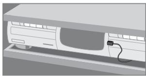
natural_image
3D rendering of a white electronic device with a cable inserted into its side panel (no text or symbols visible)natural_image
Illustration of a wireless antenna with a vertical pole and cable (no text or symbols)Remarque
natural_image
Illustration of a wireless signal detection device with a sensor and antenna, emitting sound waves (no text or symbols)natural_image
Illustration of a device connected to a speaker with a radiating light source, emitting sound waves (no text or symbols)natural_image
Illustration of a device emitting a laser beam with radiating waves (no text or symbols)natural_image
Technical diagram of a mechanical assembly with a vertical rod and mounting base (no text or symbols)natural_image
Illustration of a handheld electronic device with screwdriver and control panel (no text or symbols)This device complies with Part 15 of the FCC Rules. Operation is subject to the following two conditions:
■ This device should not cause harmful interference.
This device must accept any interference received, including interference that may cause undesired operation.
This equipment has been tested and found to comply with the limits for a Class B digital device, pursuant to part 15 of the FCC rule and ICES 003 in Canada.
These limits are designed to provide reasonable protection against harmful interference in residential installations. This equipment generates, uses, and can radiate radio frequency energy and, if not installed and used in accordance with the instructions, may cause harmful interference to radio communications.
However, there is no guarantee that interference will not occur in a particular installation. If the equipment does cause harmful interference to radio or television reception, which can be determined by turning thee equipment off and on, the user is encouraged to try to correct the interference by using one or more of the following measures:
■ Reorient or relocate the receiving antenna.
■ Increase the separation between the equipment and receiver.
■ Connect the equipment into to an outlet on a different circuit from the receiver.
- Consult the dealer or an experienced radio/TV technician for help.
CAUTION: User changes or modifications not expressly approved by the party responsible for compliance may void the user's authority to operate the equipment.
This Class B digital apparatus complies with Canadian ICES-003.
CE Regulations According to R&TTE
Declaration of Conformity
Hereby, Philips Consumer Electronics, Business Line Home Control, Interleuvenlaan 74-82, 3001 Leuven, Belgium declares under his responsibility that the RF extender SBCLI910 is in compliance with the essential requirements and other relevant provisions of Directive 1999/5/EC:
■ EMC: ETSI EN 301 489-1 and ETSI EN 301 489-3
Safety: IEC 60065
This device complies also to the WEEE Directive 2002/96/EC
Name & Signature,
Heysse Gert
Approbation & Safety Manager
Date:1-09-2005
Note: for Europe only
Disposal of Your Old Product
Your product is designed and manufactured with high quality materials and components, which can be recycled and reused. Please inform yourself about the local separate collection system for electrical and electronic products, including those marked by following symbol:

| Finnish | Philips Consumer Electronics, Business Line Home Control vakuuttaa täten että SBC LI910typpinen laite on direktiivin 1999/5/EY oleellisten vaatimusten ja sitä koskevien direktiivin muiden ehtojen mukainen. |
| Dutch | Hierbij verklaart, Philips Consumer Electronics, Business Line Home Control dat het toestel SBC LI910 in overeenstemming is met de essentiële eisen en de andere relevante bepalingen van richtlijn 1999/5/EG. |
| French | Par la présente, Philips Consumer Electronics, Business Line Home Control, déclare que l'appareil SBC LI910 est conforme aux exigences essentielles et aux autres dispositions pertinentes de la directive 1999/5/CE |
| Swedish | Härmed intygar, Philips Consumer Electronics, Business Line Home Control, att denna SBC LI910 står I överensstämmelse med de väsentliga egenskapskrav och övriga relevanta bestämmelser som framgår av direktiv 1999/5/EG. |
| Danish | Undertegnede Philips Consumer Electronics, Business Line Home Control erklærer herved, at følgende udstyr SBC LI910 overholder de væsentlige krav og øvrige relevante krav i direktiv 1999/5/EF |
| German | Hiermit erklärt Philips Consumer Electronics, Business Line Home Control die Übereinstimmung des Gerätes SBC LI910 mit den grundlegenden Anforderungen und den anderen relevanten Festlegungen der Richtlinie 1999/5/EG. |
| Greek | ME THN ΠΑΡΟΥΣΑ Philips Consumer Electronics, Business Line Home Control ΔΗΛΩΝΕΙ OTI SBC LI910 ΣΥΜΜΟΡΦΩΝΕΤΑΙ ΠΡΟΣ ΤΙΣ ΟΥΣΙΩΔΕΙΣ ΑΠΑΙΤΗΣΕΙΣ ΚΑΙ ΤΙΣ ΛΟΙΠΕΣ ΣΧΕΤΙΚΕΣ ΔΙΑΤΑΞΕΙΣ ΤΗΣ ΟΔΗΛΙΑΣ 1999/5/ΕΚ. |
| Italian | Con la presente Philips Consumer Electronics, Business Line Home Control dichiara che questo SBC LI910 è conforme ai requisiti essenziali ed alle altre disposizioni pertinenti stabilite dalla direttiva 1999/5/CE. |
| Spanish | Por medio de la presente, Philips Consumer Electronics, Business Line Home Control, declara que el SBC LI910 cumple con los requisitos esenciales y cualesquiera otras disposiciones aplicables o exigibles de la Directiva 1999/5/CE |
| Portuguese | Philips Consumer Electronics, Business Line Home Control declara que este SBC LI910 está conforme com os requisitos essenciais e outras disposições da Directiva 1999/5/CE. |
Notes - Notas - Notes
Notes - Notas - Notes