TVVR36100 - Surveillance Camera ABUS - Free user manual and instructions
Find the device manual for free TVVR36100 ABUS in PDF.
User questions about TVVR36100 ABUS
0 question about this device. Answer the ones you know or ask your own.
Ask a new question about this device
Download the instructions for your Surveillance Camera in PDF format for free! Find your manual TVVR36100 - ABUS and take your electronic device back in hand. On this page are published all the documents necessary for the use of your device. TVVR36100 by ABUS.
USER MANUAL TVVR36100 ABUS
natural_image
White wireless router device with a blue stripe and logo (no visible text or symbols)D Bedienungsanleitung
GB User guide
NL Gebruikershandleiding
FR Notice d'utilisation
DK Betjeningsvejledning
E Manual de instrucciones
PL Instrukcja obsługi
s Bruksanvisning
① Istruzioni per l'uso
RU Инструкция по эксплуатации
Version 1.0
CE
Deutsch
This user guide contains important information on starting operation and using the device.
Make sure that this user guide is handed over when the product is given to other persons.
Keep this user guide to consult later.
A list of contents with the corresponding page number can be found in the index.
Français
text_image
1 2 3 4 5 6 7 8 9 0 Q W E R T Y U I O P A S D F G H J K L Z X C V B N M a Space Enter ESCtext_image
Assistant Admin Password ***** Neues Admin Pass ... Nurses Password Bandafarge Zurück Nachsto Abbrechennatural_image
Exterior view of a modern white building with a red logo on the facade, surrounded by greenery and trees (no readable text or symbols)text_image
Dover ① ② ③ ④text_image
10 11 12 13 14 15 16 ↓ ↓ ↓ ↓ ↓ ↓ ↓ ↓ ↓ ↓ ↓ ↓ ↓ ↓ ↓ ↓ ↓ ↓ ↓ ↓ ↓ ↓ ↓ ↓ ↓ ↓ ↓ ↓ ↓ ↓ ↓ ↓ ↓ ↓ ↓ ↓ ↓ ↓ ↓ ↓ ↓ ↓ ↓ ↓ ↓ ↓ ↓ ↓ ↓ ↓ ↓ ↓ ↓ ↓ ↓ ↓ ↓ ↓ ↓ ↓ ↓ ↓ ↓ ↓ ↓ ↓ ↓ ↓ ↓ ↓ ↓ ↓ ↓ ↓ ↓ ↓ ↓ ↓ ↓ ↓ ↓ ↓ ↓ ↓ ↓ ↓ ↓ ↓ ↓ ↓ ↓ ↓ ↓ ↓ ↓ ↓ ↓ ↓ ↓ ↓ ↓ ↑ ↑ ↑ ↑ ↑ ↑ ↑ ↑ ↑ ↑ ↑ ↑ ↑ ↑ ↑ ↑ ↑ ↑ ↑ ↑ ↑ ↑ ↑ ↑ ↑ ↑ ↑ ↑ ↑ ↑ ↑ ↑ ↑ ↑ ↑ ↑ ↑ ↑ ↑ ↑ ↑ ↑ ↑ ↑ ↑ ↑ ↑ ↑ ↑ ↑ ↑ ↑ ↑ ↑ ↑ ↑ ↑ ↑ ↑ ↑ ↑ ↑ ↑ ↑ ↑ ↑ ↑ ↑ ↑ ↑ ↑ ↑ ↑ ↑ ↑ ↑ ↑ ↑ ↑ ↑ ↑ ↑ ↑ ↑ ↑ ↑ ↑ ↑ ↑ ↑ ↑ ↑ ↑ ↑ ↑ ↑ ↑ ↑ ↑ ↑ →(9) (10)(11) (12) (13) (14) (15) (16)(17)

text_image
19 20 21 22 23 24(18)(19)
text_image
Configuration Algorithms Network Networks Networks Warning Router Algorithms PPPOC USB MIP Email GPSF Webnet Einklekingen COMPS Advanced CPU Type ALBIS COUNG Other Advanced www.albis.com.cn Other Advanced Local Connections Local Connections Local Connections Local Connections Local Connections Local Connections Local Connections Local Connections Local Connections Local Connections Local Connections Local Connections Local Connections Local Connections Local Connections Local Connections Local Connections Local Connections Local Connections Local Connections Local Connections Local Connections Local Connections Local Connections Local Connections Local Connections Local Connections Local Connections Local Connections Local Connections Local Connections Local Connections Local Connections Local Connectionstext_image
Wertung File Edit File Edit Tools Help Import / Export Up data Standard Network Project Manager Tools Help Description: USB1-1 Name: Edit Type: Downloading/Download: Date: 2013-06-28 User: New Order Import Export Quicki
Hinweis
text_image
Packet Export Abbrechen,Network Time Protokoll'
,Universal Serial Bus'
86444 Affing (Germany)
ABUS 4-channel network recorder TVVR36000

natural_image
White wireless router device with a blue cable and logo on top (no visible text or symbols)User guide
Version 1.0
CE
English
This user guide contains important information on starting operation and using the device.
Make sure that this user guide is handed over when the product is given to other persons.
Keep this user guide to consult later.
A list of contents with the corresponding page number can be found in the index.
Device overview

See page 66.
Rearside
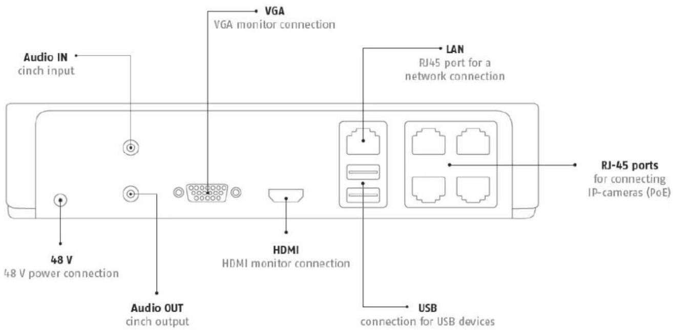
text_image
Audio IN cinch input 48 V 48 V power connection Audio OUT cinch output VGA VGA monitor connection LAN RJ45 port for a network connection HDMI HDMI monitor connection USB connection for USB devices RJ-45 ports for connecting IP-cameras (PoE)LED illumination

text_image
ABUSSystem operation
General information
The device can be controlled as follows:
• Using the USB mouse
Connections on the rear of the device

Note
Pay attention to the overview on page 65.
| No. | NameFunction |
| 1 | AUDIO IN: Cinch audio input |
| 2 | VGA:• VGA monitor connection (9-pin), video output signal |
| 3 | LAN:• Ethernet LAN connection |
| 4 | RJ45 connections:• Connection of up to four PoE cameras |
| 5 | USB:• USB connections for operating with a mouse and data export |
| 6 | HDMI• HDMI monitor connection |
| 7 | AUDIO OUT:• Cinch audio output (synchronised with the video output) |
| 8 | POWER SUPPLY• 48 V DC connection for power supply |
Mouse operation
i
Note
Further descriptions in these operating instructions are made with the mouse.
The device is suitable for use with a USB mouse. Connect the mouse to the USB port.
| Button | Function |
| Left | Single-click:Selection in the menu, activation of an input field or a TAB, display of the Quick Set menuDouble-click:Switches between the screen display of single and multiple images in the live view and during playbackClick and drag:Set-up of alarm areas or zones |
| Right | Single-click:Calls up the pop-up menu |
| Scroll wheel | In the live view:Shows previous / next camera |
Device overview 64
System operation....65
General information 65
Connections on the rear of the device 65
Mouse operation....66
Quick guide....70
Before you start....70
Installing the HDD 70
Establishing the connections 70
Configuring the device 70
Important safety information....71
Explanation of symbols....71
Proper use 71
General information 71
Power supply 71
Overloading / overvoltage 72
Cables 72
Installation location / operating environment ....72
Remote control....72
Care and maintenance....73
Accessories....73
Putting into operation....73
Children and the device 73
Introduction 74
General information 74
Unpacking the device....74
Scope of delivery 74
On-screen keyboard 75
Starting the device 75
Switching off, locking and rebooting the device....75
Status displays....76
General information ....76
DVR LED status bar....76
Display on the monitor 76
Setup wizard....77
Setting up the system 77
Setting up the administrator....77
Time / Date 77
Network Settings....78
HDD Management....78
Camera assistant....78
Camera recording 79
Live view 80
Overview 80
Status symbols 80
Pop-up menu for mouse operation 80
Selection bar in the camera image 81
Settings 82
Setting the camera output 82
Playback....83
Contents
General information 83
Playback screen....83
Using the control panel....83
Selecting playback type....84
Main menu 85
Menu overview 85
Menu description 85
Menu description 86
Configuration......87
Overview....87
General 87
Terms and definitions 88
Network layout....89
Network-configuration 89
Alarm....93
Warning....94
User....95
Camera....97
Camera 97
OSD 97
Image 97
Motion 97
Handling....98
Private Zone....98
Tamper monitoring....99
Video signal loss....99
Record....101
Setting up....101
Schedule....101
Encoding....102
Record....102
TAB Substream....102
Advanced settings 103
Holidays....103
HDD 104
HDDs....104
Installing the HDD 104
HDD Management parameters ....104
HDD settings of the cameras....105
Panic recording....106
Recording....106
Alarm....106
Video Export......107
Duration....107
Event (event type 'Motion') 108
Maintenance ....109
System Info 109
Log Search....109
Import / Export 110
Upgrade 110
Default....111
Network....111
S.M.A.R.T....113
Checking the hard disk drive status ....113
Shutdown....114
Display....114
Settings: Recording 114
Settings: Network 114
Troubleshooting....115
Device cleaning and care....115
Note....115
Technical data 116
Disposal 117
Glossary....118
Overview of specialist terms 118
Internal HDD 120
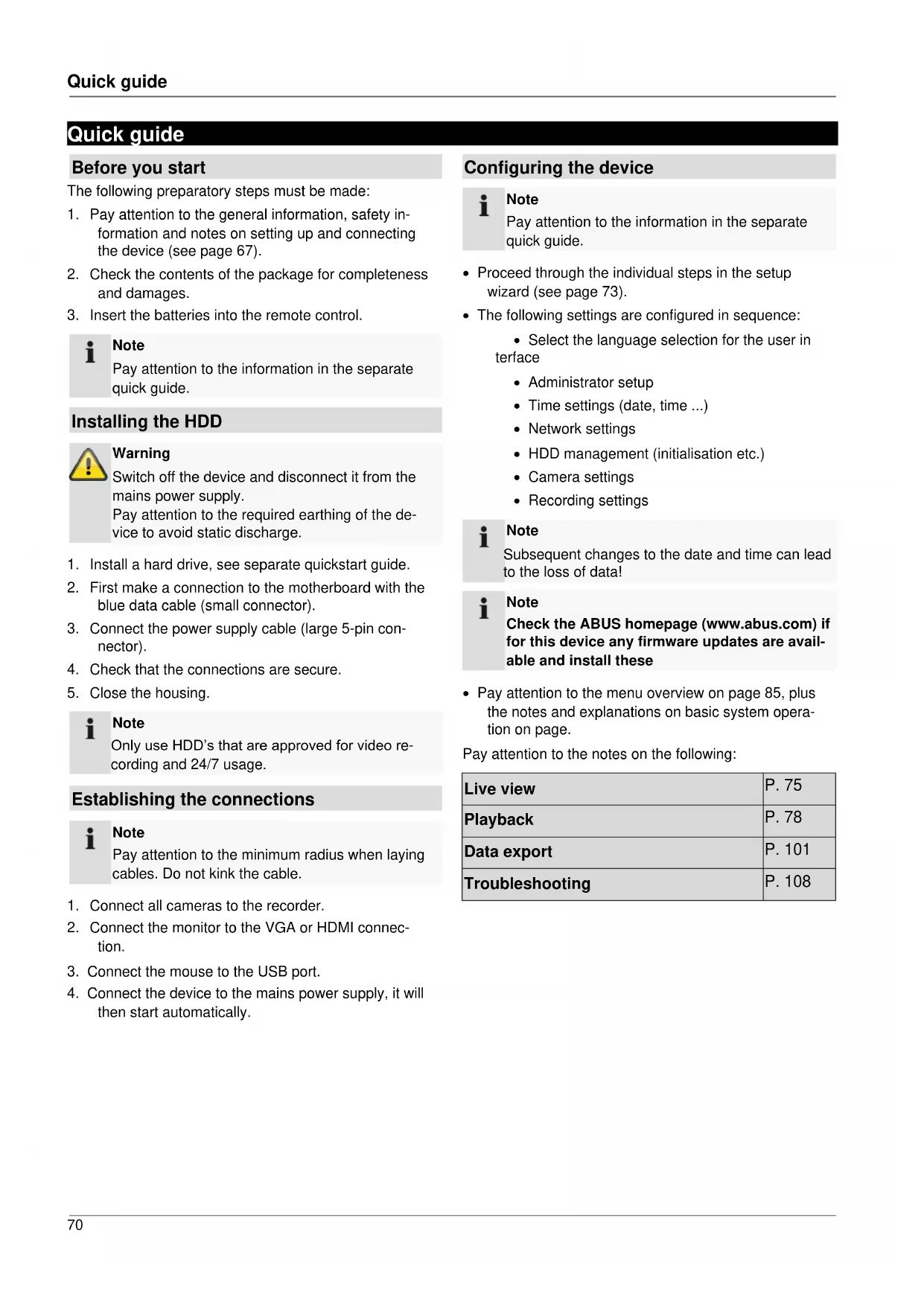
Quick guide
Before you start
The following preparatory steps must be made:
- Pay attention to the general information, safety information and notes on setting up and connecting the device (see page 67).
- Check the contents of the package for completeness and damages.
- Insert the batteries into the remote control.

Note
Pay attention to the information in the separate quick guide.
Installing the HDD

Warning
Switch off the device and disconnect it from the mains power supply. Pay attention to the required earthing of the device to avoid static discharge.
- Install a hard drive, see separate quickstart guide.
- First make a connection to the motherboard with the blue data cable (small connector).
- Connect the power supply cable (large 5-pin connector).
- Check that the connections are secure.
- Close the housing.

Note
Only use HDD's that are approved for video recording and 24/7 usage.
Establishing the connections

Note
Pay attention to the minimum radius when laying cables. Do not kink the cable.
- Connect all cameras to the recorder.
- Connect the monitor to the VGA or HDMI connection.
- Connect the mouse to the USB port.
- Connect the device to the mains power supply, it will then start automatically.
Configuring the device

Note
Pay attention to the information in the separate quick guide.
- Proceed through the individual steps in the setup wizard (see page 73).
-
The following settings are configured in sequence:
-
Select the language selection for the user interface
- Administrator setup
• Time settings (date, time ...)
• Network settings
• HDD management (initialisation etc.) - Camera settings
- Recording settings

Note
Subsequent changes to the date and time can lead to the loss of data!

Note
Check the ABUS homepage (www.abus.com) if for this device any firmware updates are available and install these
- Pay attention to the menu overview on page 85, plus the notes and explanations on basic system operation on page.
Pay attention to the notes on the following:
| Live view | P. 75 |
| Playback | P. 78 |
| Data export | P. 101 |
| Troubleshooting | P. 108 |
Important safety information
Explanation of symbols
The following symbols are used in this manual and on the device:
Symbol Signal word Meaning


Warning Indicates a risk of injury or health hazards.
Warning Indicates a risk of injury or health hazards caused by electrical voltage.
Important Indicates possible damage to the device/accessories.
Note Indicates important information.
The following labels are used in the text:
| Meaning | |
| 1.... | Set of tasks or instructions with a defined sequence in the text |
| 2.... | |
| ... | Set of points or warnings without a defined sequence in the text |
| ... |
Proper use
Only use the device for the purpose which it was designed and built for. Any other use is considered inappropriate.
This device may only be used for the following purpose(s):
- This 4-channel network recorder is used in combination with connected video signal sources (network cameras) and video output devices (TFT monitors) for object surveillance.

Note
Data storage is subject to national data-protection guidelines.
During installation, inform your customers regarding the existence of these guidelines.
General information
Before using the device for the first time, read the following instructions carefully and pay attention to all warnings, even if you are already familiar with electronic devices.

Warning
All guarantee claims become invalid for damages caused by non-compliance with these operating instructions.
We cannot be held liable for resulting damages.

Warning
We cannot be held liable in the event of material or personal damage caused by improper operation or non-compliance with the safety information.
All guarantee claims are invalid in such cases.
Keep this manual in a safe place for future reference.
If you pass on or sell the device, you must also include this user manual.
This device has been manufactured in accordance with international safety standards.
Power supply
- Only operate this device through a power source which supplies the mains power specified on the type plate.
- If you are unsure of the power supply at the installation location, contact your power supply company.

Warning
Avoid data loss!
Always use an uninterruptible power supply (UPS) with overvoltage protection.
- Disconnect the device from the mains power supply before carrying out maintenance or installation work.
- The on/off switch does not completely disconnect the device from the mains power supply.
- To disconnect the device completely from the mains power supply, the plug must be disconnected from the mains socket. Therefore, the device should be positioned so that direct and unobstructed access to the mains socket is guaranteed at all times and the plug can be disconnected immediately in an emergency.
To avoid the possibility of fires, the plug should always be disconnected from the network socket if the device is not used for long periods. Disconnect the device from the mains power supply before impending electrical storms, or use an uninterruptible power supply.

Warning
Never open the device on your own! There is a risk of electric shocks!
If it is necessary to open the device, consult trained personnel or your local maintenance specialist.
- The installation or modification of a HDD should only be made by trained personnel or your local maintenance specialist.

Warning
The installation of additional equipment or modification of the device invalidates your guarantee if not carried out by trained personnel.
We recommend having the HDD installed by a maintenance specialist.
Your guarantee is invalidated in the event of improper installation of the HDD.
Overloading / overvoltage
- Avoid overloading of mains sockets, extension cables and adapters as this can result in fires or electric shocks.
- Use overvoltage protection to prevent damages caused by overvoltage (e.g. electrical storms).
Cables
- Always hold cables by the connector, and do not pull the cable itself.
- Never touch the mains cable with wet hands, as this can lead to a short circuit or electric shock.
- Never position the device, furniture or other heavy items on the cable. Ensure that the cable does not become kinked, especially on the connector and sockets.
- Never knot the cable, and do not tie it to other cables.
- All cables should be laid so that they cannot be stepped on or cause an obstruction.
- A damaged mains cable can cause a fire or electric shock. Check the mains cable from time to time.
- Never modify or manipulate the mains cable or plug.
- Do not use plug adapters or extension cables that do not conform to the applicable safety standards, and do not make alterations to power supply cables or mains cables.
Installation location / operating environment
- Position the device on a firm, level surface and do not place any heavy objects on the device.
- The device is not designed for operation in rooms subject to high temperatures or moisture (e.g. bathrooms), or in excessively dusty rooms.
- Operating temperature and ambient humidity: -10 °C to 55 °C, maximum 85% relative humidity. The device may only be operated in moderate climate conditions.
Ensure the following:
- Sufficient ventilation must be present at all times (do not place the device in a storage rack, on thick carpets, on a bed or anywhere where the ventilation slots are covered. Make sure that a gap of at least 10 cm is present on all sides).
- The device must not be exposed to direct heat sources (e.g. heaters).
- The device must not be exposed to direct sunlight or strong artificial light.
- The device must not be placed in close proximity to magnetic fields (e.g. loudspeakers).
- Naked flames (e.g. candles) must not be placed on or near the device.
- Contact with spraying or dripping water and aggressive liquids must be avoided.
- The device must not be operated in close proximity to water, and must not be submerged under any circumstances (do not place objects containing water on or near the device, such as vases or drinks).
- Foreign objects must not penetrate the device.
- The device must not be exposed to strong variations in temperature, as this can lead to condensation and electrical short circuits.
- The device must not be exposed to excessive jolts or vibrations.
Remote control
- Remove all batteries if the device will not be used for a sustained period, as these can leak and damage the device.
Care and maintenance
Maintenance is necessary if the device has been damaged. This includes damage to the plug, mains cable and housing, penetration of the interior by liquids or foreign objects, exposure to rain or moisture or when the device does not work properly or has fallen.
- Disconnect the device from the mains power supply before maintenance (e.g. cleaning).
- If smoke develops or unusual noises or odours are detected, then switch off the device immediately and pull the mains plug from the socket. In such cases, the device should not be used until it has been inspected by a qualified technician.
- Maintenance work should only be carried out by qualified specialists.
- Never open the housing on the device or accessories. There is a risk of fatal injury due to an electric shock when the housing is opened.
- Clean the device housing and remote control with a damp cloth.
- Do not use solvents, white spirit or thinners as these can damage the surface of the device.
- Do not use any of the following substances:
- Salt water, insecticides, solvents containing chlorine or acids (ammonium chloride) or scouring powder.
- Gently rub the surface with a cotton cloth until it is completely dry.

Warning
The device works under dangerous voltages. The device must only be opened by authorised specialists. All maintenance and service work must be carried out by authorised firms. Improper repairs can expose device users to the risk of fatal injury.
Accessories
- Only connect devices that are suitable for the intended purpose. Otherwise, hazardous situations or damage to the device can occur.
Putting into operation
- Observe all safety and operating instructions before putting the device into operation for the first time.
- Only open the housing to install the HDD.

Warning
When installing the device in an existing video surveillance system, ensure that all devices are disconnected from the mains power supply and low-voltage circuit.

Warning
If in doubt, have a specialist technician carry out assembly, installation and connection of the device.
Improper or unprofessional work on the mains power supply or domestic installation puts both you and other persons at risk.
Connect the installations so that the mains power circuit and low-voltage circuit always run separately from each other. They should not be connected at any point or become connected as a result of a malfunction.
Children and the device
- Do not allow children access to electrical devices. Never allow children to use electrical devices without supervision. Children may not be able to accurately detect possible risks. Small parts can be life-threatening if swallowed.
- Keep batteries away from small children. Call for medical assistance immediately if a battery is swallowed.
- Keep packaging materials away from children (danger of suffocation).
- This device should not be used by children. If used improperly, spring-loaded parts can be ejected and cause injuries to children (e.g. eye injuries).
Introduction
Dear customers,
This device complies with the requirements of the applicable EU directives.
The declaration of conformity can be ordered from:
To maintain this status and to guarantee safe operation, it is your obligation to observe these operating instructions!
Read the entire operating manual carefully before putting the product into operation and pay attention to all operating and safety information!
All company names and product descriptions are trademarks of the corresponding owner. All rights reserved.
In the event of questions, please contact your local maintenance specialist or dealer.

Disclaimer
These operating instructions have been produced with the greatest care. Should you discover any missing information or inaccuracies, please contact us under the address shown on the back of the manual. ABUS Security-Center GmbH does not accept any liability for technical and typographical errors, and reserves the right to make changes to the product and operating instructions at any time and without prior warning. ABUS Security-Center GmbH is not liable or responsible for direct or indirect damages resulting from the equipment, performance and use of this product. No forms of guarantee are accepted for the contents of this document.
General information
In order to use the device correctly, read this user manual carefully and keep it in a safe place for later use.
This manual contains instructions on recorder operation and maintenance. Consult an authorised specialist if the device needs to be repaired.
Unpacking the device
Handle the device with extreme care when unpacking it.
The packaging is made of reusable materials, and should always be passed on for recycling.
We recommend the following:
Paper, plastic packaging, cardboard and corrugated cardboard should be disposed of in the appropriate recycling containers.
If recycling containers are not available in your local area, then you can dispose of these materials as domestic waste.
If the original packaging has been damaged, inspect the device. If the device shows signs of damage, then return it in the original packaging and contact the manufacturer.
Scope of delivery
• ABUS 4-channel network video recorder
- Power supply unit
- USB mouse
- SATA cable and screws for hard drives
• CD
- User manual
- Quick guide
On-screen keyboard
The on-screen keyboard appears after clicking on a text entry field with the mouse:

text_image
1 2 3 4 5 6 7 8 9 0 Q W E R T Y U I O P A S D F G H J K L Z X C V B N M a Space Enter ESCThe following screen keyboard appears during mere numerical entry:

text_image
1 2 3 4 5 6 7 8 9 . 0 Space Enter ESCThe keys have the same function as on a computer keyboard.
• To enter the character, left-click the mouse.
• To finish data entry, press Enter.
- To delete the character in front of the cursor, click on ←.
- To switch between upper and lower case, click on the framed a symbol. The current setting is displayed above the keyboard.
- To cancel the entry or exit the field, press ESC.
Starting the device

Important
The device must only be operated with the mains power specified on the type plate.
For safety reasons, use an uninterruptible power supply (UPS).
When the device is connected to the power supply, it starts up automatically and the LED status bar glows.
- The device carries out a self-test during the start-up procedure.
- The setup wizard appears. Exit the wizard to access the live view.
Switching off, locking and rebooting the device
Click on "Shutdown" in the main menu. The overview appears.
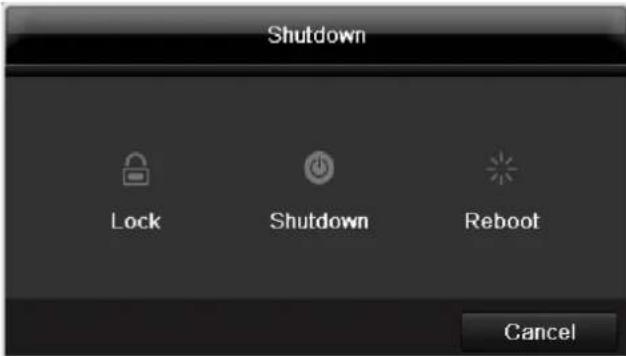
text_image
Shutdown Lock Shutdown Reboot Cancel-
To switch off the device, select ShutDown and confirm by pressing Yes. The device is then switched off.
-
Do not press any keys during the shutdown procedure.
-
Now pull out the plug of the power supply unit.
-
To lock the system, select the corresponding Lock symbol on the left. The user interface is now locked and a password must be entered to access the menu.
- To reboot the device, select the corresponding Re-boot symbol on the right. The device is then rebooted.
Switching on the device
- Plug in the power supply unit to start the device.
Status displays
General information
The following status displays indicate the current operating state:
• LEDs on the front of the device
• Acoustic signal tones
- Icons (display elements) on the monitor

Note
Pay attention to the information in the separate quick guide.
DVR LED status bar
| State | Function |
| Blue (constantly lit) | System status is OK |
| Off | The device is switched off or the status display has been manually deactivated in the display. |
Display on the monitor
The device shows the date and time, camera name and whether a recording is in progress.
• Continuous recording: blue "R"
- Motion detection recording yellow "R"
Setup wizard
Setting up the system
The setup wizard guides you through the necessary basic system settings. The network video recorder is then set up for recording and surveillance.

Note
All detailed settings can be found in the device menu (see overview on page 60).
The language selection appears after switching on for the first time:
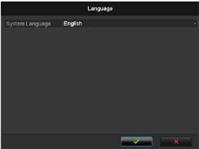
text_image
Language System Language English- Click the entry field and select the desired language from the list. Click √ to confirm the message. The following query appears:
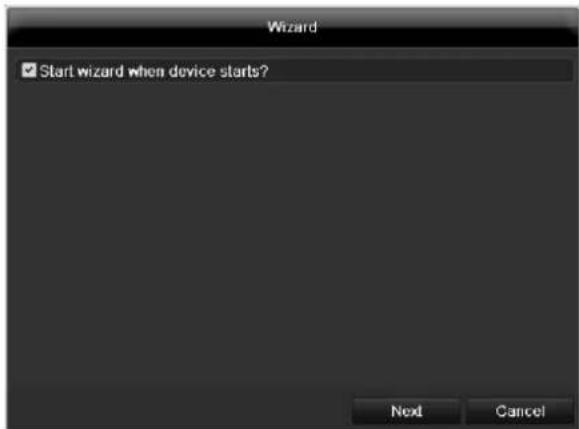
text_image
Wizard ✓ Start wizard when device starts? Next Cancel- Click on Next to start the wizard.

Note
After the system is set up, you can untick the box. The setup wizard is then no longer started automatically.
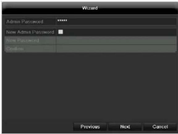
Setting up the administrator

Warning
Note down the admin password. The following password is preset
“1 2 3 4 5”
text_image
Wizard Admin Password ****** New Admin Password * New Password Continu Previous Next Cancel- Click the entry field and enter your admin password.
- To assign a new password, tick the box next to New Admin Password.
- Enter the new password and confirm in the field below.
- Click on Next.
Time / Date
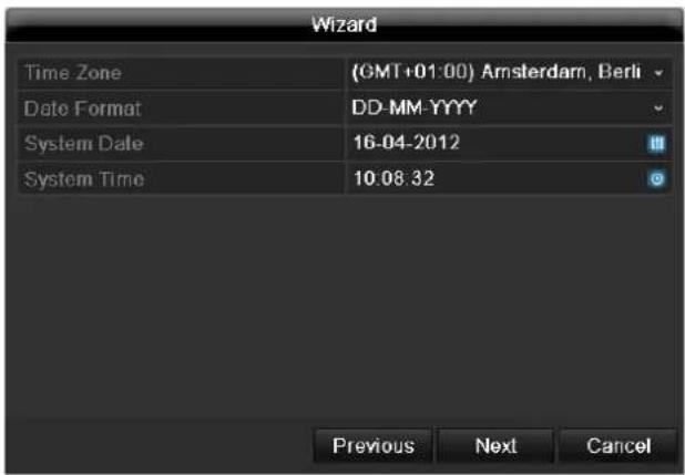
text_image
Wizard Time Zone (GMT+01:00) Amsterdam, Berli Date Format DD-MM-YYYY System Date 16-04-2012 System Time 10:08:32 Previous Next CancelEnter the system time (date and time). Click on Next to accept the data.
Network Settings
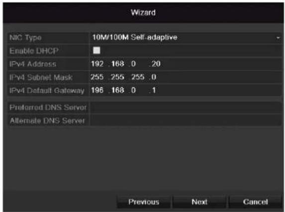
text_image
Wizard NIC Type 10M/100M Self-adaptive Enable DHCP IPv4 Address 192 .168 .0 .20 IPv4 Subnet Mask 255 .255 .255 .0 IPv4 Default Gateway 196 .168 .0 .1 Preferred DNS Server Alternate DNS Server Previous Next Canceli
Note
To check whether DHCP can be selected (or if you have to set the IP address and other settings manually), consult your network administrator.
- DHCP activated: If DHCP is set up in the network router, then tick the DHCP box. All network settings are then made automatically.
- DHCP not activated: Enter the data manually (IPv4 address, IPv4 subnet mask and IPv4default gateway = IPv4 address of the router). You can also optionally enter the address of the DNS server that you need for sending the E-mail.
A typical address specification is as follows:
• IPv4 address: 192.168.0.50
• IPv4 Subnet mask: 255.255.255.0
• IPv4 Default gateway: 192.168.0.1
• Preferred DNS server: 192.168.0.1
i
Note
When the device is accessed remotely via the internet, it should be given a fixed network address.
i
Note
The following cameras are fully integrated with the ABUS protocol and can be configured using the setup wizard: TVIP11560, TVIP41500, TVIP61500, TVIP61550.
HDD Management
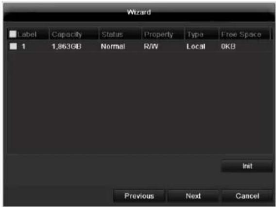
text_image
Wizard Label Capacity Status Property Way Type Free Space 1 1,863GB Normal R/W Local 0KB Init Previous Next Cancel- To set up a new hard disc, activate the "Check box" with a left click and then click on Init.

Warning
All data on the drive is deleted!
- Confirm the prompt by pressing OK. The HDD is then set up for operation. The progress is displayed on the status bar.
- Exit the setting by pressing Next.
Camera assistant
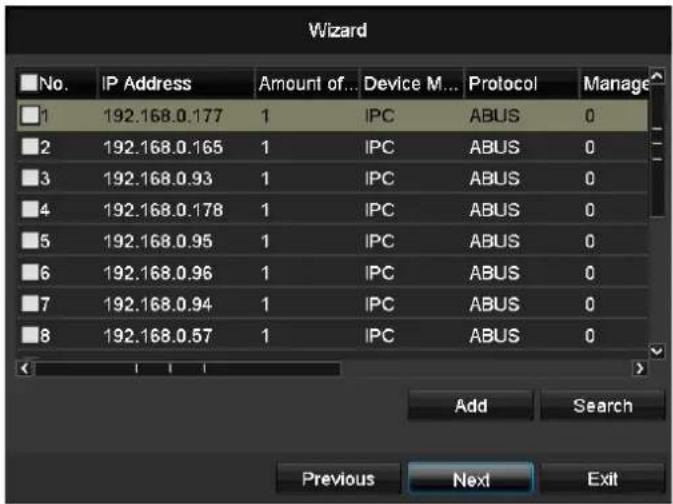
text_image
Wizard No. IP Address Amount of... Device M... Protocol Manage 1 192.168.0.177 1 IPC ABUS 0 2 192.168.0.165 1 IPC ABUS 0 3 192.168.0.93 1 IPC ABUS 0 4 192.168.0.178 1 IPC ABUS 0 5 192.168.0.95 1 IPC ABUS 0 6 192.168.0.96 1 IPC ABUS 0 7 192.168.0.94 1 IPC ABUS 0 8 192.168.0.57 1 IPC ABUS 0 Add Search Previous Next Exit- Click Search to see the network cameras in your network.
- To add network cameras, activate the required cameras and click Add.
- Click Next to proceed with the setup.
Camera recording
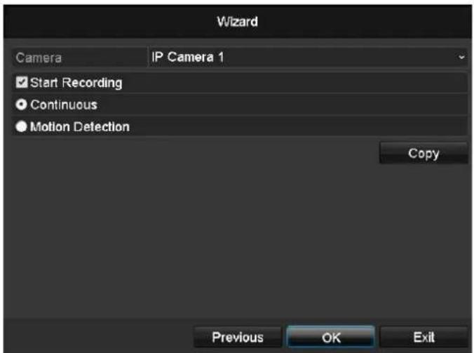
text_image
Wizard Camera IP Camera 1 ✓ Start Recording ● Continuous ● Motion Detection Copy Previous OK Exit- For "Camera", select a network camera which you want to record with
- Activate the check box "Start recording".
- Select the type of recording. You can choose between "Time plan" and "Motion recognition". Arm the motion detection inside the camera for recording motion.
- Press Copy to take on the setting for other cameras. For this, select the cameras that appear in the new window. Activate the respective check box with a mouse click.
- Finalize the setting and end the installation assistant with OK.
Live view
Overview
The live view starts automatically after the device is switched on.
You can also go back to the live view by pressing the Menu key repeatedly.
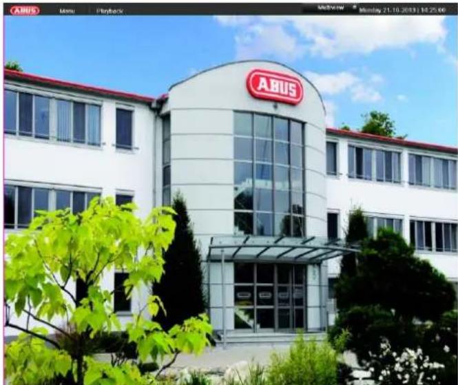
natural_image
Exterior view of a modern white building with a red 'ABUS' logo on the facade, surrounded by greenery and trees (no signage text in focus)The following menus are found in the screen header:
- Menu
- Playback
- PTZ
The view pop-up menu is found on the right. The time and date are displayed on the right.
- Click on the symbol to open the pop-up menu of the multi view.
- Click on one of the symbols to switch between the different views.


The signals of the connected cameras are displayed on the main screen.
- By double-clicking the left mouse key, you can display the camera image as a full-screen view or switch back to the original view.
Status symbols
- The following symbols are displayed depending on the operating status of the device:
| Symbol | Meaning |
| R | Yellow: Motion RecordingRecording at motion detection |
| R | Blue: RecordingContinuous recording |
Pop-up menu for mouse operation

Note
Press the right mouse button when the cursor is positioned on a live image.
The following settings can be made. The arrow pointing to the right indicates that a sub-menu is opened for selection:
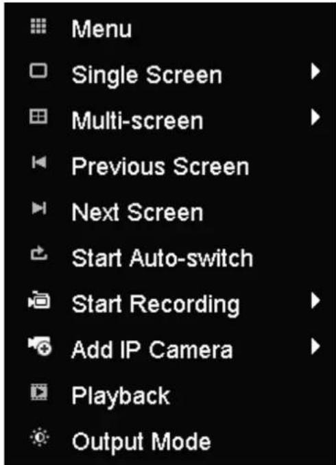
text_image
Menu Single Screen Multi-screen Previous Screen Next Screen Start Auto-switch Start Recording Add IP Camera Playback Output Mode| Menu | Opens the main menu |
| Single Screen | Full-screen view for selected camera |
| Multi Screen | Various camera layouts |
| Previous Screen | Changing the presentation of the previous camera |
| Next Screen | Displays the next camera(s) |
| Start Auto-Switch | Starts the camera sequence |
| Start Recording | Starts motion detection or the schedule for the entire day |
| Add network camera | Adds a network camera |
| Playback | Switches to playback mode |
| Activate the audio | Activates the audio output (VGA/HDMI) for the live view. |

Note
Stop Auto-switch:
Specify the delay in the image sequence in the display settings.
Selection bar in the camera image
Click on the camera image in single or multi view. A selection bar appears:
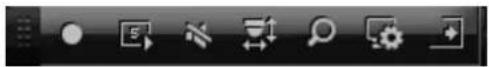
(1)
(2)
(3)
(4)
(5)
(6)
(7)
| No. | Meaning/function |
| (1) | Area for moving the miniature bar |
| (2) | Activate/deactivate manual recording |
| (3) | Instant playback of the last 5 minutes |
| (4) | Activate/deactivate the audio function |
| (5) | Digital zoom |
| (6) | Picture display settings |
| (7) | Close the selection list |
Settings

Note
The live view can be set as follows.
Open the main menu, then click on "Configuration". Then click on "Liveview":
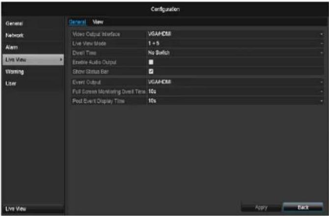
text_image
Configuration General New Network Alarm Live View Warning User Video Output Interface VGA/HDMI Live View Mode 1 + 5 Dwell Time No Switch Enable Audio Output Show Status Bar ✓ Event Output VGA/HDMI Full Screen Monitoring Over Time 10s Post Event Display Time 10s Live View Apply BackThe following settings are available in the TAB "General":
| Video Output Interface | VGA/HDMISelect the connection where the settings are changed |
| Live View Mode | Different camera layouts1x1, 2x2, 1x5 |
| Dwell Time | Switching time between the individual cameras and the sequence display |
| Activate the audio | Activates the audio output (VGA/HDMI) for the live view. |
| Display the status bar | Activate/deactivate the status bar |
| Event Output | Allocate monitor for the output of events |
| Full Screen Monitoring Duration | in seconds, where the event on the allocated monitor will be displayed. |
| Post Event Display Time | in seconds, the duration of the Pop-up window when an event occurs. |

Note VGA monitor connected:
A connected VGA monitor automatically becomes the main monitor where the audio output is also assigned. The BNC output Video Spot Out output displays the cameras in sequence and in full screen.
No HDMI monitor connected:
If the HDMI cable is not connected to the monitor at the start, the main video signal is emitted at the Main VGA connection. Connect the VGA cable and start the recorder again to perform the automatic detection.
Setting the camera output
You can display a maximum of 4 cameras simultaneously in the live view.
- Click on the TAB "View".
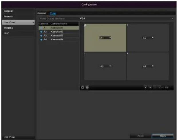
text_image
Configuration General Network Live View Warning Clear Video Output Options VSM Camera Camom Kama A1 Kamera B1 A2 Kamera B2 A3 Kamera B3 A4 Kamera B4 A1 A2 A3 A4 Live View Apply Help-
Select the display mode.
-
1 × 1
- 2×2
-
1×5
-
The camera signal is assigned to the corresponding image section using the navigation keys.
- "X" means that this camera is not displayed.
- Click on Apply to accept the settings.
Playback
General information
Playback can be made in three different ways:
• Through the video search in the main menu
- From the live view
• Through the log file in the maintenance menu
i
Note
The buttons "previous file/day/event" are used differently depending on the playback mode:
Normal playback:
By pressing the button the playback jumps to the previous/next day.
Video Search:
By pressing the button the playback jumps to the previous/next event day.
Video Export:
By pressing the button the playback jumps to the previous/next file.
i
Note
It is possible to start a simultaneous playback with up to 4/8 cameras.
Playback screen
Playback is controlled on the control panel:
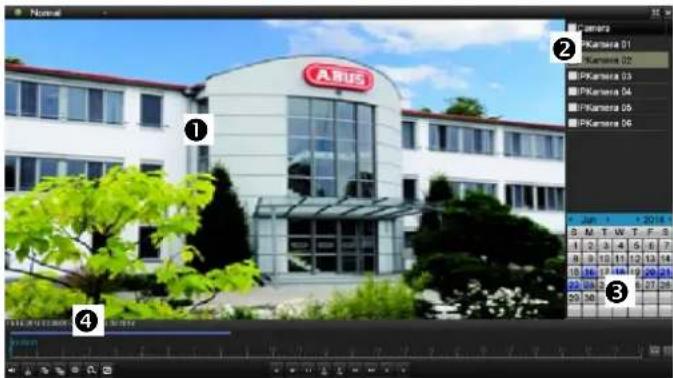
text_image
Normal Camera PKamera 01 PKamera 02 PKamera 03 PKamera 04 PKamera 05 PKamera 06 PKamera 07 A.HUS 3 1 2 3 4 5 6 7 8 9 10 11 12 13 14 15 16 17 18 19 20 21 22 23 24 25 26 27 28 29 30 31 32 33 34 35 36 37 38 39 40 41 42 43 44 45 46 47 48 49 50 51 52 53 54 55 56 57 58 59 60 61 62 63 64 65 66 67 68 69 70 71 72 73 74 75 76 77 78 79 80 81 82 83 84 85 86 87 88 89 90 91 92 93 94 95 96 97 98 99 100| No. | Area |
| 1 | Running playback with date and time |
| 2 | Used to select the camera for feedback |
| 3 | Calendar with recording type |
| 4 | Control panel with time bar (see right) |
Using the control panel
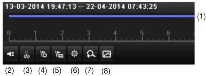
The control panel (4) is used for controlling the running playback. The symbols have the following meaning
text_image
13-03-2014 19:47:13 -- 22-04-2014 07:43:25 (1) 0 1 2 3 4 5 6 (2) (3) (4) (5) (6) (7) (8)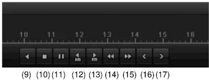
text_image
(9) (10) (11) (12) (13) (14) (15) (16) (17)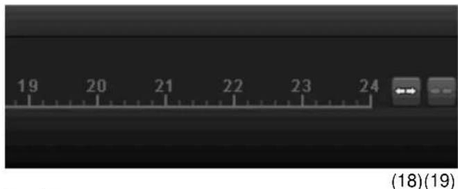
text_image
19 20 21 22 23 24 (18)(19)| No. | Meaning/function |
| 1 | Time bar:Click on the time bar with the mouse to continue playback from another pointTo start playback from a specific time, click on the slider and drag it to the required time |
| 2 | Activate/deactivate audios |
| 3 | Start/stop the video clip export. When exiting playback, the clip is displayed in the export dialog. |
| 4 | Add marking (see “Marking” playback type) |
| 5 | Add user-defined marking (see “Marking” play-back type) |
| 6 | Manage markings |
| 7 | Digital zoom |
| 8 | Smart search:By creating a search window, motion data is shown from the recordings in the selected viewing area in the time scale.Note:The smart search is only possible for one camera's playback. |
| 9 | Reverse playback |
| 10 | Stops playback |
| 11 | Starts/pauses playback |
| 12 | Goes back 30 seconds |
| 13 | Advances 30 seconds |
| 14 | Slow-motion advance (16x → 1x) |
| 15 | Fast-forward advance (1x → 16x) |
| 16 | Previous day |
| 17 | Next day |
| 18 | Minimise time scale section |
| 19 | Maximise time scale section |
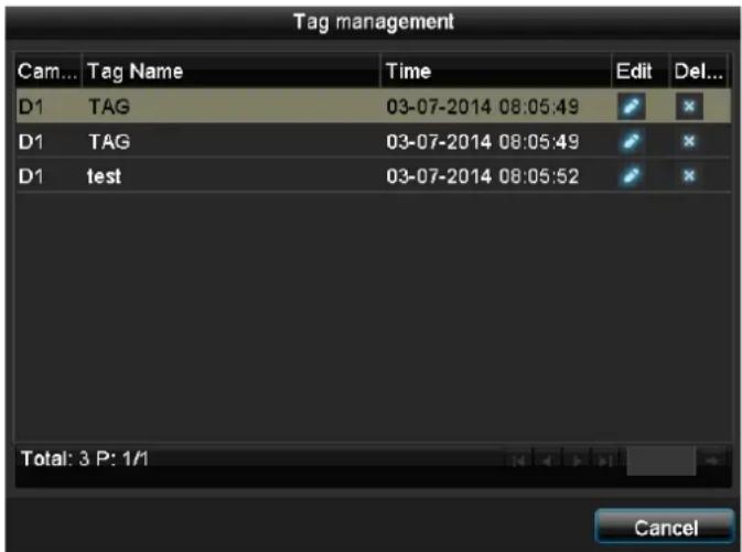
Please klick on, Tag management' (6):
text_image
Tag management Cam... Tag Name Time Edit Del... D1 TAG 03-07-2014 08:05:49 D1 TAG 03-07-2014 08:05:49 D1 test 03-07-2014 08:05:52 Total: 3 P: 1/1 Cancel- In order to change the description of your marking, click on the process symbol. To remove, click on the delete symbol.
Selecting playback type
By selecting the type of playback (5), various types of recordings and events can be displayed and filtered in the playback view.
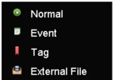
text_image
Normal Event Tag External FileThe following menus are available:
| Type | Description |
| Permanent | Recorded video data playback |
| Event | Searching and playing video data which was recorded by means of motion detection or alarm input. |
| Marking | Searching and playing video data which was provided by means of marking. |
| External file | Searching and playing video data which was found on an external data storage device (USB). |
Main menu
Menu overview
The following overview shows the main menus used to set and control the device.
Furthermore you can find important information regarding the device on the right side of the menu.
- Click on the menu to open it.
- Click Exit to close the menu overview.
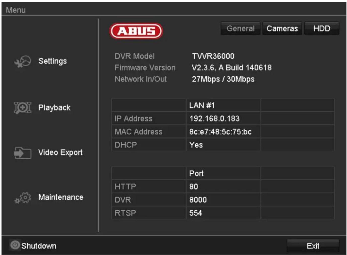
text_image
Menu Settings Playback Video Export Maintenance ABUS General Cameras HDD DVR Model TVWR36000 Firmware Version V2.3.6, A Build 140618 Network In/Out 27Mbps / 30Mbps LAN #1 IP Address 192.168.0.183 MAC Address 8c:e7:48:5c:75:bc DHCP Yes Port HTTP 80 DVR 8000 RTSP 554 Shutdown ExitMenu description
| Menu | Description | See page... |
| Settings | Includes the menus Configuration, Camera, Record, HDD, Playback. | 81 |
| Playback | Parameter-controlled search for video and image recordings which were triggered by events such as motion detection, as well as markings set in playback. | 100 |
| Video Export | Parameter-controlled search for video and image recordings which were triggered by events such as alarms or motion detection, as well as alarm events and markings set in playback. | 101 |
| Maintenance | System information, searching logs, importing/exporting configurations, device maintenance such as updating new firmware, loading factory settings, displaying network loads. | 103 |
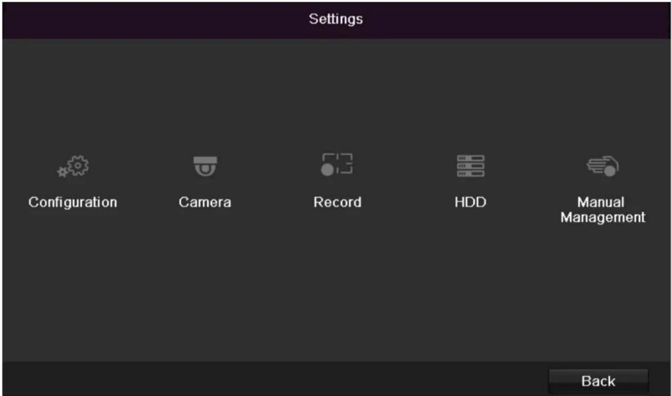
text_image
Settings Configuration Camera Record HDD Manual Management BackMenu description
| Menu | description | page |
| Configuration | Used for managing all device settings (General, Network, Live View, Exception, User). | 82 |
| Camera | Menu for setting camera parameters (OSD configuration, image mode, motion recognition, Private Zone, Tamper Monitoring, Video Loss). | 90 |
| Record | Menu to set recording parameters (time plan, camera resolution, camera stream etc.). | 94 |
| HDD | Used for initialising or managing installed HDD (assigning read/write functions, cameras, network HDD management etc.). | 97 |
| Manual Management | Menu for setting manual recordings. | 99 |
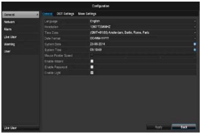
Configuration
text_image
Configuration General DGT Settings More Settings Language English Resolution 126C72046HZ Time Zone (GMT+01.00) Amsterdam, Berlin, Rome, Paris Date Format DO/MM/YYYY System Date 23-06-2014 System Time 09:10:49 Mouse Printer Speed Enable Wizard Enable Password Enable Light Apply Back Live View
Note
The "Configuration" menu is used to manage all device settings.

Warning
Ensure that the date and time are set correctly. IMPORTANT:
Subsequent changes to the settings can lead to data loss!
Ensure a data backup has been made in good time beforehand.
Overview
| Menu | Setting | Page |
| General | Language, video, time, date, mouse pointer, password, time zones and other settings | 82 |
| Network | Required network settings (manual IP, DHCP, PPPOE, DDNS etc.) and network status overview | 83 |
| Alarm | Settings for the alarm I/Os of the network camera | 83 |
| Live cast | Display settings and assignment of the event output | 85 |
| Warning | Behaviour of the device in exceptional cases (HDD full, network disconnected etc.) | 88 |
| User | Adding and changing users, assigning authorisation rights | 88 |

Note
Pay attention to the instructions in the corresponding sections.
General
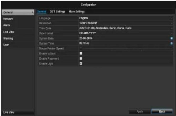
text_image
Configuration General DST Settings More Settings Language English Resolution 1230°720/50HZ Time Zone (GMT+01:30) Amsterdam, Berlin, Rome, Paris Date Format DD/MM/YYYY System Date 23-06-2014 System Time 09:10:49 Mouse Pointer Speed Enable Wizard Enable Password Enable Light Apply Back Live View| “General” tab | Setting |
| Language | Language on the OSD |
| Resolution | Resolution on the monitor |
| Time Zone | GMT (Greenwich Mean Time) |
| Date Format | MM-DD-YYYY, DD-MM-YYYY, YYYY-MM-DD |
| System Date/Time | Date and time |
| Mouse Pointer Speed | Set on the scroll bar (left = low speed; right = high speed) |
| Enable Wizard | Box ticked:Wizard will appear after restart of the device. |
| Enable ID Authentication | Box not ticked:In order to enter a menu no password has to be entered. At access by network the password has to be entered.Box ticked:Password must be entered in order to use the menu. |
| Activating LED status bar | Box not ticked:The LED status display is deactivated.Box ticked:The LED status display glows blue when the recorder is on. |
| Activate remote access | Box ticked: Access for remote configuration is activated for technical support. |
| TAB “DST settings” | Setting |
| Auto DST Adjustment | With an activated check box, the device converts automatically to summer time. |
| Enable DST | With an activated check box, an exact start / end date can be selected |
| From / To | Date of DST start / end |
| DST Bias | Daylight Saving Time Bias: Correction of the DST to the reference time |
| TAB “More Settings” | Setting |
| Device Name | Unique specification of the device |
| Device Number | Used for unique identification when using CMS software |
| Auto. log off | Never / 1 to 30 minutes – regulates how long the menu is shown |
| Event message | Box ticked:Automatic alarming when notifications such as motion detection , HDD full, etc. occur. |
Confirm the settings by clicking Apply and leave the menu with OK.
Network configuration
Correct network settings are essential in the following cases:
- When using remote control of the device and surveillance over your server
i
Note
Please read the following basic instructions before setting up the device.
A network is a connection of at least two network-capable devices.
Transmission types:
- Wired networks (e.g. CAT5 cable)
• Wireless networks (WLAN)
• Other transmission types (Powerline)
All systems have certain similarities, but can also differ in many ways.
Terms and definitions
An overview of relevant terms when using the device in a network can be found below.
| Parameter | Setting |
| IP address | An IP address is the unique address of a network device within a network.This address may only appear once within a network. Certain IP address ranges are reserved for public networks (e.g. the Internet). |
| Private address range | e.g. 10.0.0.0 – 10.255.255.255Subnet mask: 255.0.0.0172.16.0.0 - 172.31.255.255Subnet mask: 255.255.0.0192.168.0.0 - 192.168.255.255Subnet mask: 255.255.255.0 |
| Subnet mask | A subnet mask is a bit mask used for making decisions and assignments during routing.255.255.255.0 is the standard subnet mask in home networks. |
| Gateway | A gateway is a network device which allows all other network devices to access the Internet.This can be the computer connected to the DSL modem or – usually – the router or access point within the network. |
| Parameter | Setting |
| Name server | The name server is responsible for assigning a unique IP address to a web address or URL (e.g. www.google.de). Also known as DNS (Domain Name Server).When a domain name is entered into a browser, the DNS searches for the corresponding IP address of the server and forwards the query on.The IP of the provider's DNS can be entered here. However, it is often sufficient to select the IP of the gateway. This then forwards the queries independently to the provider DNS. |
| DHCP | The DHCP server automatically assigns the IP address, subnet mask, gateway and name server to a network device.DHCPs are available in current routers. The DHCP service must be specially set and activated (see the corresponding manual for more information).Note:When using fixed IP addresses and a DHCP server, make sure that the fixed IP addresses are outside the address range assigned by DHCP. Otherwise, problems could occur. |
| Port | A port is an interface used for communication by different programs. Certain ports are fixed (23: Telnet, 21: FTP), whilst others can be freely selected. Ports are important for different applications (e.g. external access to the device over a browser). |
| MAC address | The MAC address (Media Access Control or Ethernet ID) is the specific hardware address of the network adapter. This is used for the unique identification of the device in a computer network. |
Network layout
The device must be physically connected to the network over a CAT5 cable (see the connections on page 60).

Note
Pay attention to the specific information and instructions on the network devices.
Several switches, routers and access points can be connected to each other. Firewalls and other security software can affect the network.

Warning
When using a router, the network clients (e.g. the recorder) can be connected to the Internet and vice versa.
Make sure to use protective measures to prevent unauthorised external access (e.g. firewall, changing passwords, changing ports)!
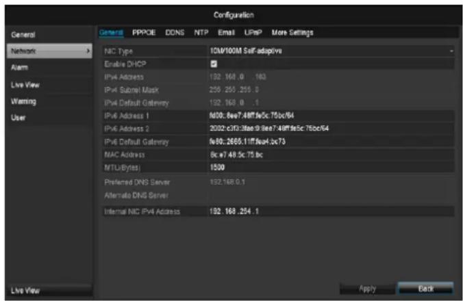
Network-configuration
text_image
Configuration General Network Alarm Live View Warning User General PPPOE DDNS NTP Email LFP More Settings NIC Type 10M/100M Self-adaptive Enable DHCP IPv4 Address 192.168.0 183 IPv4 Subnet Mask 255.255.255.0 IPv4 Default Gateway 192.168.0 .1 IPv4 Address 1 f600.8ee7.48fffe5c:75bcf64 IPv4 Address 2 2002.c3D:3fee9fee7.48fffe5c:75bcf64 IPv4 Default Gateway fe80::2665.11fffe4c2c73 MAC Address 8c w7.48.5c:75 bc MTU(Bytes) 1500 Preferred DNS Server 192.168.0.1 Alternate DNS Server Internal NIC IPv4 Address 192.168.254.1 Live View Apply Back| TAB | Settings |
| General | Settings for the local net and selecting the network mode. |
| PPPOE | PPPOE is used on ADSL connections and when using modems in Germany. Click on “Set” to enter the access data (ID and password) for your provider. |
| DDNS | Server for Dynamic Domain Name System management. Used for updating host names or DNS entries |
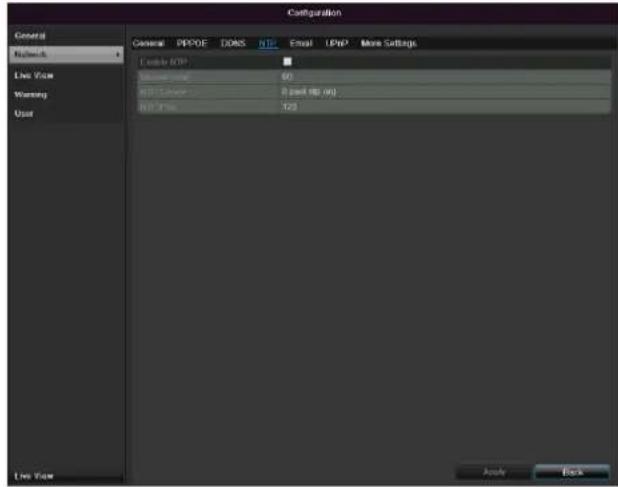
| NTP | Network Time ProtocolServer for time synchronisation |
| Used to specify the e-mail settings which are sent as an e-mail to a specific address in the event of an alarm. | |
| UPnP | Universal Plug and PlaySettings for the convenient control of network devices in an IP network. |
| More Settings | Used to configure the IP address of the PC where a message should be displayed in the event of an alarm |
TAB General
| Parameter | Setting |
| NIC Typ | Set the transmission speed of the installed network card here. Tip: 10M/100/1000M self adaptive |
| Enable DHCP | Tick the box if the IP addresses are assigned dynamically via DHCP in the network. DHCP activated: Subsequent entry fields are inactive (parameters assigned via DHCP). Note: If the IP addresses are assigned manually, ensure that DHCP is not active (box not ticked). |
| IPv4 Adress | Address of the network device in the network (manual assignment) |
| IPv4 Subnet Mask | Usually 255.255.255.0 |
| IPv4 Default Gateway | Address of the gateway for Internet access |
| IPv6 address 1 | Local (local link) IPv6 address |
| IPv6 address 2 | Global (global unicatst) IPv6 address |
| IPv6 standard gateway | IPv6 address of the gateway for Internet access. |
| MAC Adress | Hardware address of the installed network card |
| MTU (Bytes) | Describes the max. size of the largest protocol data . |
| Preferred DNS Server | Address of the Domain Name Server (usually the IP address of the gateway) |
| Alternate DNS | IP address of the alternative DNS server |

Note
In certain modes some of these settings cannot be selected.
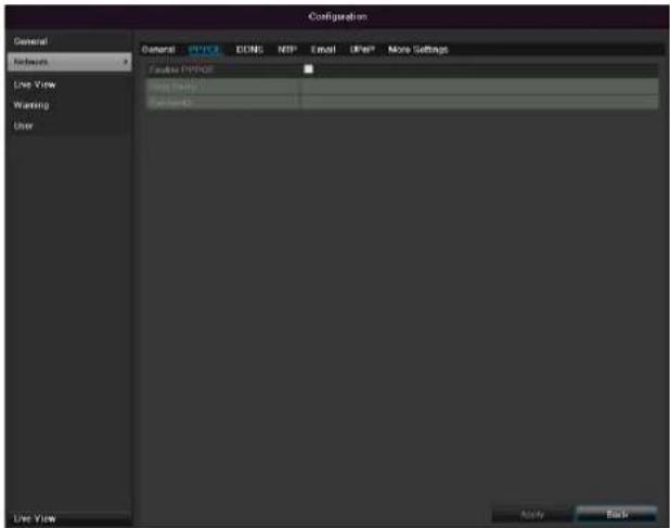
PPPOE
text_image
Configuration General Network Live View Warning User Current PIPROE Long Island Settings Live View Apply Help-
Tick the PPPOE box, enter the user name (Internet access ID) and password, then confirm the password.
-
Confirm the settings by pressing Apply.

Warning
Use PPPOE only if there is no router available.
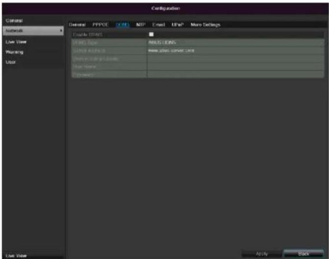
DDNS
text_image
Configuration General PPPOE IN MTP Email UFP# More Settings Create ID/ID IP address Network directory New address server unit User Name Description Apply Back Live View-
To use the ABUS DDNS function, you must first set up an account under www.abus-server.com. Please note the FAQs on the website when doing this.
-
Tick the "Enable DDNS" box, enter 'ABUS DDNS' as the "DDNS Type", then enter www.abus-server.com or "62.153.88.107" under "Server Address".
-
Confirm the settings by pressing Apply. The IP address of your Internet connection is now updated on the server every minute.
NTP
text_image
Configuration General General PVPOE DOS FTP Email UPP More Settings Network Live View Warning User Enable TCP 80 USB Command 2 pad (81 port) USB Phone 123 Live View Analog Back
Note
The recorder can synchronise the time with an external server. Several server addresses are available on the Internet for this purpose.
-
Tick the "Enable NTP" box and then enter the interval at which the synchronisation should be made again. Enter the IP address of the NTP server and the NTP port.
-
Confirm the settings by pressing Apply.
In the event of an alarm, the device can send a message by e-mail. Enter the e-mail configuration here:
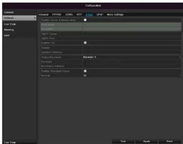
text_image
Configuration General Network User View Wearing User Cable Server Authentication User Base Network SMTP Server SMTP Port Custom TCP Service Service's Address Select Services Recover 1 Release Recover's Address Enable Adjusted Picture Normal 2s Text Apply Back| Parameter | Setting |
| Enable Server Authentica... | Tick the box when authentication is made on the server of the Internet provider |
| User Name | E-mail account at the provider |
| Password | Password connected to the e-mail account |
| SMTP Server | SMTP server address of the provider |
| SMTP Port | Enter the SMTP port here (Default: 25) |
| Enable SSL | Tick the box to activate the e-mail encryption |
| Sender | Name of the sender |
| Sender's Adresse | Corresponding e-mail address for the e-mail account |
| Sender's Receiver | Select three possible recipients for the e-mail |
| Receiver | Enter the name of the recipient here |
| Receiver's Adresse | Enter the e-mail address of the recipient here |
| Attach picture | Tick the box when camera images should also be sent with the email as photo files |
| Interval | Select a triggering time between 2 and 5 seconds. The images are only sent if motion was detected during the defined time. |
-
Enter the parameters of the e-mail notification.
-
Click on Test to send a test e-mail.
-
Please clarify if your settings are correct and you have received a confirmation mail. Then click on Apply.
i
Note
The device sends an e-mail to the specified recipients.
If the e-mail is not received, check the settings and correct them.
If necessary, check the spam filter of your e-mail client.
i
Note
You obtain the access data and settings for sending SMTP from your email provider. Some email providers only provide SSL encryption for sending emails. This recorder was tested for SSL compatibility with the following providers: GMX, Web.de, Gmail.
UPnP
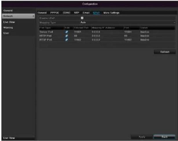
text_image
Configuration General Network Live Vire Warning User Enable UHP* Mapping Type Auto Port Type Edit Personal Port Mapping ID Address Port Status Server Port 11001 0.0.0.0 11001 Inactive HTTP Port 89 0.0.0.0 89 Inactive HTTP Port 11002 0.0.0.0 11002 Inactive Refresh Live Vire Apply Back| Parameter | Setting |
| Enable UPnP | Tick the box to activate visibility in an IP network. When this function is activated, port forwarding is automatically entered in the router for all network ports (provided the UPnP is activated in the router).When UPnP is enabled, they are sent to the ABUS server by the UPnP-configured network ports (provided ABUS DDNS is enabled). |
| Mapping Type | For “Manual” setting, the network ports can be manually defined using the “Edit” button.For “Auto” setting, the recorder checks for any free network ports on the router and determines the port numbers according to a random pattern. |
Confirm the settings by clicking Apply and exit the menu with Back.
More settings
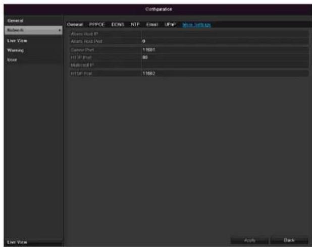
text_image
Configuration General Network Live View Warning User General PPCE EONS NTP Email UDP More Settings Atmos Road IP Atmos Road Post 0 Carrier Port 11681 HTTP Port 80 Multiport IP HTTP Port 11682 Live View Apply Back| Parameter | Setting |
| Alarm Host IP | Network address of the CMS station |
| Alarm Host Port | Port of your CMS station |
| Server Port | Port for data communication (General: 8000) |
| HTTP Port | Port for web server (General: 80) |
| Multicast IP | In order to minimize traffic you can enter a Multicast IP. |
| RTSP Service Port | RTSP-port(Default: 554) |
i
Note
Server port 8000 and HTTP port 80 are the standard ports for remote clients and remote Internet browser access.
Alarm

Note
This menu item is only available if a compatible camera with alarm input and output is connected e.g. TVIP11560.
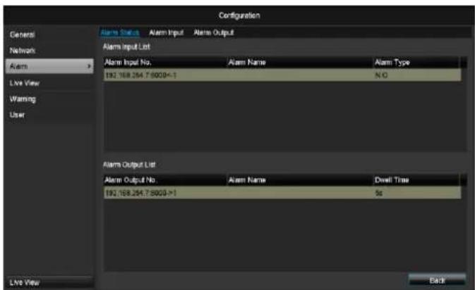
Alarm status
text_image
Configuration General Network Alarm Live View Warning User Alarm Select Alarm Input Alarm Output Alarm Input List Alarm Input No. Alarm Name Alarm Type 192.168.254.7.8000->1 N.G. Alarm Output List Alarm Output No Alarm Name Dwell Time 192.168.254.7.8000->1 5s Live View BackHere you see a list with all the alarm inputs and outputs of the network cameras and their current status.
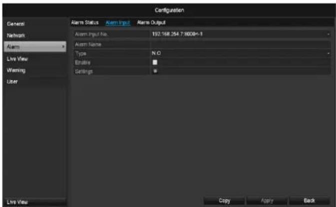
Alarm input
text_image
Configuration General Network Alarm Live View Warning User Alarm Status Alarm Input Alarm Output Alarm Input No. 192.168.264.7-8008+1 Alarm Name Type N.O. Enable Settings Live View Copy Apply Back- Select a reaction in the case of an alarm by clicking the 'Setting' symbol for "Reaction".
| Parameter | Setting |
| Alarm input | Select the alarm input to make the settings You can select the alarm input using the network address data. |
| Alarm name | Enter a clear description here (e.g. door contact on warehouse) |
| Type | N.O.: Normally open circuitN.C.: Normally closed circuit |
- Activate the alarm input by ticking the box for "Settings".
- Define the response of the recorder when there is an alarm at "Reaction".
- Click Copy to apply these settings for other cameras.
- Confirm the settings by clicking Apply and exit the menu with Back.
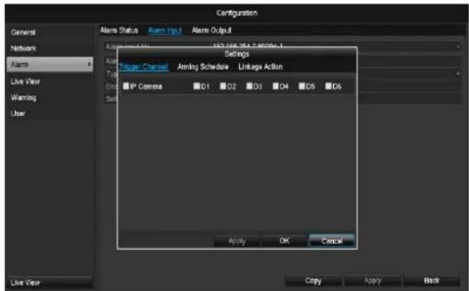
Settings
TAB Trigger channel
text_image
Configuration General Network Alarms Live View Warning User Alarms Status Alarm Input Alarms Output Settings Trigger Channel Arming Schedule Linkages Action IP Camera D1 D2 D3 D4 D5 D6 Apply OK Cancel Live View Copy Apply BackTick a box to select which camera channel is triggered when there is an alarm.
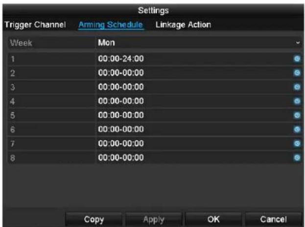
TAB Activate schedule
text_image
Settings Trigger Channel Arming Schedule Linkage Action Week Mon 1 00:00-24:00 2 00:00-00:00 3 00:00-00:00 4 00:00-00:00 5 00:00-00:00 6 00:00-00:00 7 00:00-00:00 8 00:00-00:00 Copy Apply OK Cancel- Define the time at which the responses selected in the TAB "Reaction" are activated when there is an alarm.
- Click "Copy" to apply these settings for other days of the week or the entire week.
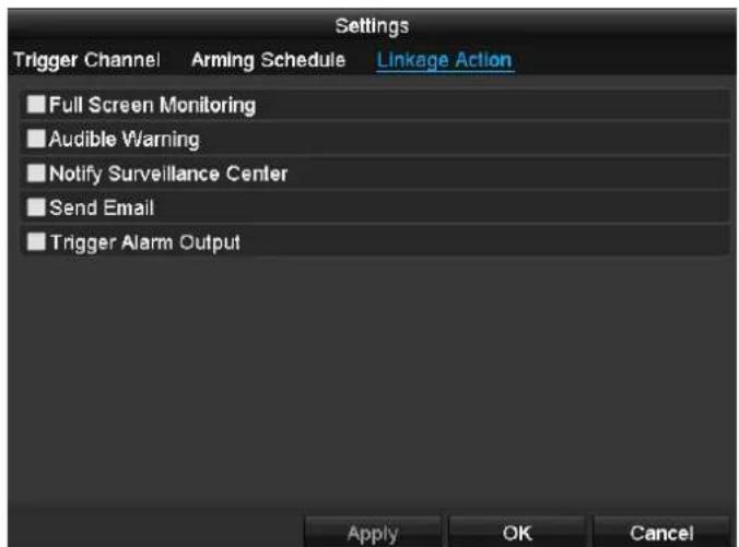
Link action
Select the TAB Link action.
Here you can configure the response of the recorder for an alarm by ticking a box.
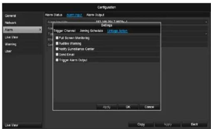
text_image
Configuration General Network Alarms Live View Warning User Alarms Status Alarm Input Alarm Output AppWizard Name: 183.168.354.7.900e-1 Settings Trigger Channel Aming Schedule Linkage Action Full Screen Monitoring Audible Warning Notify Surveillance Center Send Email Trigger Alarm Output Apply OK Cancel Live View Copy Apply Back| Parameter | Notifications |
| Full-screen pop-up | The camera is displayed as a full-screen picture in live cast |
| Audible Warning | The device emits a repeating tone. |
| Notify CMS | The CMS emits an audible warning tone. |
| Send email | An email is sent to a specific email address. See page 29 |
| Trigger alarm output | The alarm output is triggered in the event of an alarm. |
- Confirm the settings by clicking Apply and exit the menu with OK.
Alarm output
i Note This menu item is only available if a compatible camera with alarm output is connected e.g. TVIP11560.
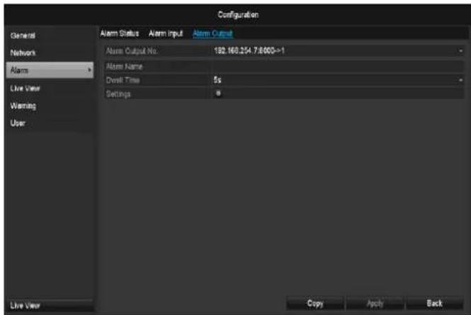
text_image
Configuration General Network Alarm Live User Warning User Alarm Status Alarm Input Alarm Output Alarm Output No 192.160.254 7:000->1 Alarm Name Dwell Time 5s Settings Live User Copy Arch Back- Select a reaction in the event of an alarm by clicking the 'Setting' symbol for "Reaction".
| Parameter | Setting |
| Alarm output | Select the alarm output to make the settings. You can select the alarm output using the network address data. |
| Alarm Name | Enter a clear description here (e.g. door contact on warehouse) |
| Dwell Time | Select the dwell time for switching the alarm output. |
- Activate the alarm input by ticking the box for "Settings".
- Define the response of the recorder when there is an alarm at "Settings".
- Click Copy to apply these settings for other cameras.
- Confirm the settings by clicking Apply and exit the menu with Back.
Settings
Activating the time plan
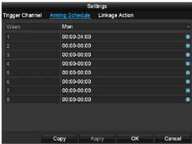
text_image
Settings Trigger Channel Arming Schedule Linkage Action Week Mon 1 00:00-24:00 2 00:00-00:00 3 00:00-00:00 4 00:00-00:00 5 00:00-00:00 6 00:00-00:00 7 00:00-00:00 8 00:00-00:00 Copy Apply OK Cancel- Set the time at which the alarm output should be activated.
Warning
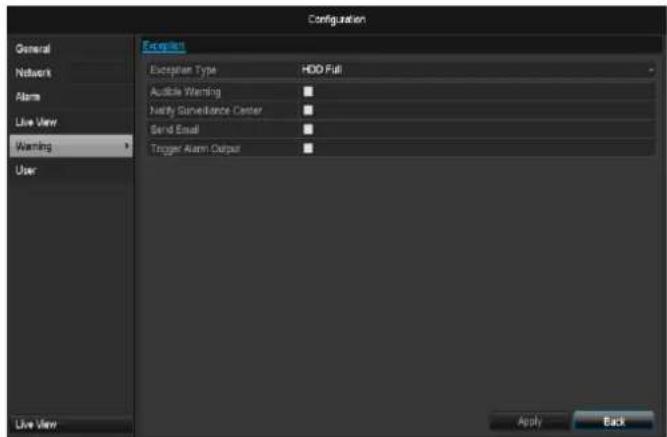
text_image
Configuration General Network Alarm Live View Warning User Exception Type HDD Full Auditable Warning Notify Surveillance Center Send Email Trigger Alarm Output Live View Apply BackYou can trigger a warning for the following error types:
- HDD Full
- HDD Error
• Network Disconnected - IP Conflict
- Illegal Login
- Exception Error
| Parameter | Notifications |
| Audible Warning | The device emits a repeating tone. |
| Notify CMS | A message is sent to the event log of the CMS software. |
| Send email | An email is sent to a specific email address. |
| Trigger alarm output | The selected alarm output is switched in the event of a fault. |
User

text_image
Configuration User Management No. Parameters Local NAVS Address Per... Edit Delete 1 Limit Configuration Remote Configuration Camera Configuration Local Log Search Local Parameters Settings Local Camera Management Local Advanced Operation Local Shutdown / Reboot Apply OK Cancel Live View Add Back
Warning
Note down the admin password. The following password is preset
"1 2 3 4 5"
You can add new users, delete existing users and change the settings in the "User Management" menu.
- To add a new user, select Add.
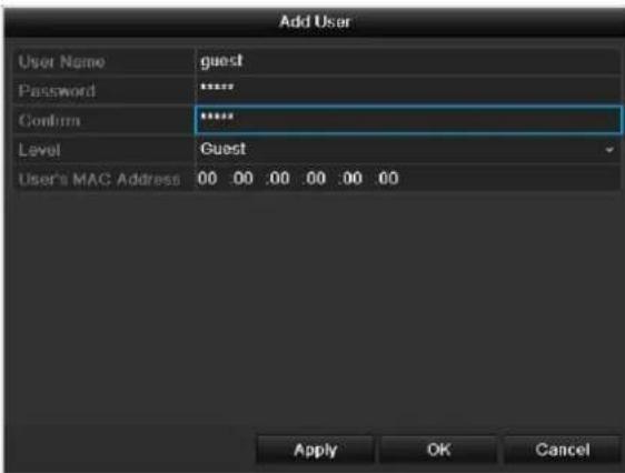
text_image
Add User User Name guest Password ****** Confirm ****** Level Guest User's MAC Address 00 00 00 00 00 00 Apply OK Cancel| Parameter | Setting |
| User Name | Unique identification |
| Password | Access code for the device (device management)Note: Change all passwords on a regular basis, using a combination of letters and numbers. Note down all passwords in a safe place. |
| Confirm | Enter the access code again here |
| Level | IMPORTANT:More access rights can be set on the Manager level than on the User level. |
| User's MAC | MAC address of the network adapter |
| Address | on the PC of the corresponding userNote:This limits access to the PC whose MAC address is entered here! |
- Enter the name and password and confirm the password in the field below.
- Select the level and enter the MAC address.
- Confirm the settings by clicking Apply.

Warning
Pay attention to the instructions below on assigning access rights.
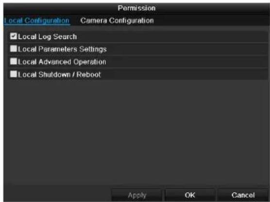
Setting permission rights
Control the access rights of the user by clicking the "Right" symbol. Only the access data of users added manually can be changed:
text_image
Permission Local Configuration Camera Configuration ✓ Local Log Search ■ Local Parameters Settings ■ Local Advanced Operation ■ Local Shutdown / Reboot Apply OK Cancel
Note
The user can make the settings locally (i.e. on the device) or change the parameters.
The user can access the device via the network connection.
The "Camera Permission" tab is used to set access rights for individual cameras (network or local).
| Parameter | Setting |
| Local configuration | Local log searchLocal parameter settingsLocal camera managementAdvanced settingsNetwork shutdown / reboot |
| Remote configuration | Camera rights:Remote log searchRemote parameter settingsRemote camera managementRemote video output controlTwo-way audioRemote alarm controlAdvanced settingsRemote reboot |
| Camera configuration | Camera rights:Remote live viewLocal manual controlRemote manual controlLocal playRemote playLocal video export |

Warning
Change the general settings of the user (name, password, level, MAC address) by clicking the "Edit" symbol or in the TAB "Change password".
Camera
Camera
text_image
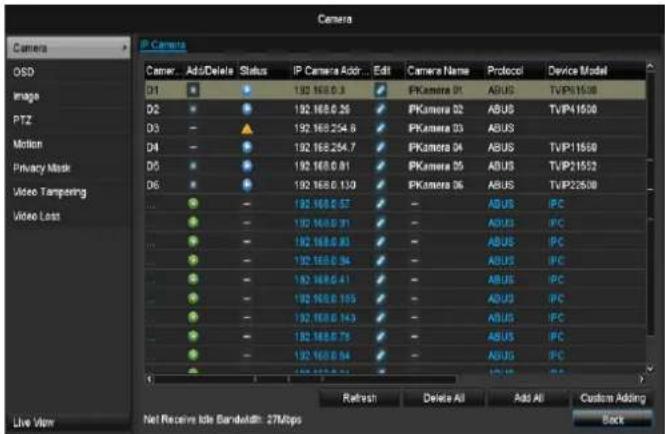
Camera DSD Image PTZ Motion Privacy Mask Video Tampering Video Loss Live View IP Camera Camera... Add/Delete Status IP Camera Add... Edit Camera Name Protocol Device Model D1 192 168.0.3 PKamera 01 ABUS TVVP1500 D2 192 168.0.26 PKamera 02 ABUS TVVP1500 D3 192 168.254.6 PKamera 03 ABUS D4 192 168.254.7 PKamera 04 ABUS TVVP11500 D5 192 168.0.81 PKamera 05 ABUS TVVP21552 D6 192 168.0.130 PKamera 06 ABUS TVVP22500 ... 192 168.0.57 - ABUS PC ... 192 168.0.91 - ABUS PC ... 192 168.0.93 - ABUS PC ... 192 168.0.94 - ABUS PC ... 192 168.0.41 - ABUS PC ... 192 168.0.105 - ABUS PC ... 192 168.0.143 - ABUS PC ... 192 168.0.75 - ABUS PC ... 192 168.0.94 - ABUS PC Refresh Delete All Add All Custom Adding Back Net Receive Idle Bandwidth: 27MbpsSelect the required channel under "Camera". Click Refresh to see the network cameras in your network.
Click Delete all to delete the cameras already added.
Click Add all to add all the displayed cameras. Note that a maximum of 6 channels can be added.
Select User defined to add a camera manually.
OSD
text_image
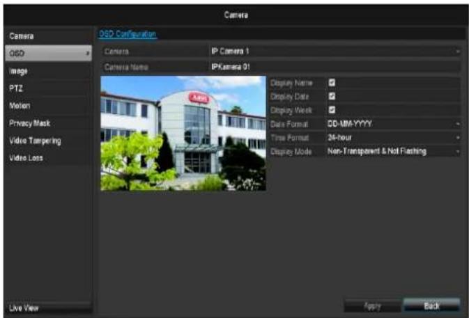
Camera O5D Configuration Camera IP Camera 1 Camera Name IPKamera 01 Display Name Display Date Display Week Data Format DD-MM-YYYY Time Format 24-hour Display Mode Non-Transparent & Not Flashing Live View Apply Back| Camera | Camera to be set |
| Camera Name | Allocation of camera name |
| Display Name | Activate/deactivate display of camera name in the live view |
| Display Date | Activate/deactivate display of date in the live view |
| Display Week | Activate/deactivate display of week in the live view |
| Date Format | Selection of date display type |
| Time Format | 12 hours/24 hours |
| Display Mode | Settings relating to the presentation of camera name and date |
| OSD font | Changing the font size |
Image
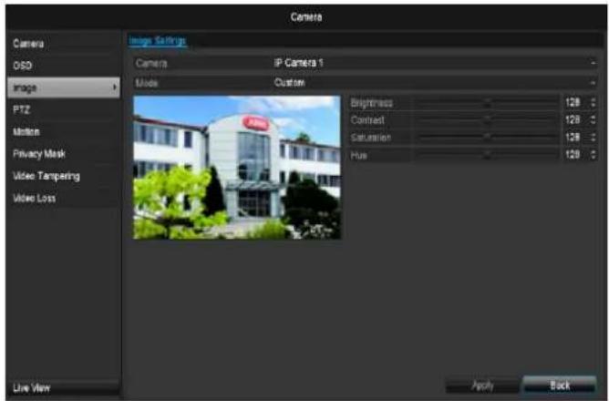
text_image
Camera Image Settings Camera IP Camera 1 Mode Custom PTZ Motion Privacy Mask Video Tampering Video Loss Live View Brightness 128 ° Contrast 128 ° Saturation 128 ° Hue 128 ° Apply BackSelect the camera channel to be processed at "Camera". Adapt the camera image to light conditions at "Mode" by means of specified settings or with user-defined settings.
Motion
Select the camera channel under "Camera".
Select the checkbox for the motion detection.

Note
In order to record using the motion recognition, you must set the time plan at recording (see p.94).
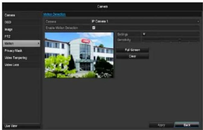
text_image
Camera Camera Image PT2 Motion Privacy Mask Video Targeting Video Loss Live View Motion Detection Camera IP Camera 1 Enable Motion Detection Settings Sensitivity Full Screen Clear Apply BackHandling
Trigger Channel
When "Reaction" is clicked, the TAB Trigger channel appears (only with motion recognition):
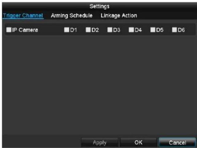
text_image
Settings Trigger Channel Arming Schedule Linkage Action IP Camera D1 D2 D3 D4 D5 D6 Apply OK CancelSelect one or more camera channels that should carry out a reaction in the event of an alarm.
Confirm the settings by clicking Apply and leave the menu with OK.
Armin Schedule
Select the TAB Arming Schedule.
Here you set the times when the reactions in the TAB Reaction are triggered.
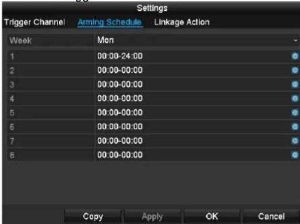
text_image
Settings Trigger Channel Arming Schedule Linkage Action Week Mon 1 00:00-24:00 2 00:00-00:00 3 00:00-00:00 4 00:00-00:00 5 00:00-00:00 6 00:00-00:00 7 00:00-00:00 8 00:00-00:00 Copy Apply OK Cancel- Select the day and enter the schedule.
- Select whether the settings should be applied to all days of the week with using Copy.
- Confirm the settings by clicking Apply and leave the menu with OK.
Handling
Select the TAB Reaction.
Here you can configure the response of the recorder for an alarm by ticking a box.
text_image
Handling Trigger Channel Arming Schedule Handling Full Screen Monitoring Audible Warning Send Email Apply OK Cancel| Parameter | Notifications |
| Full-screen pop-up | The camera is displayed as a full-screen picture in live cast |
| Audible Warning | The device emits a repeating tone. |
| Notify CMS | The CMS emits an audible warning tone. |
| Send email | An email is sent to a specific email address. See page 29 |
| Trigger alarm output | The alarm output is triggered in the event of an alarm. |
- Confirm the settings by clicking Apply and leave the menu with OK
Private Zone
Select the camera channel under "Camera".
Select the checkbox for activating the private zone.
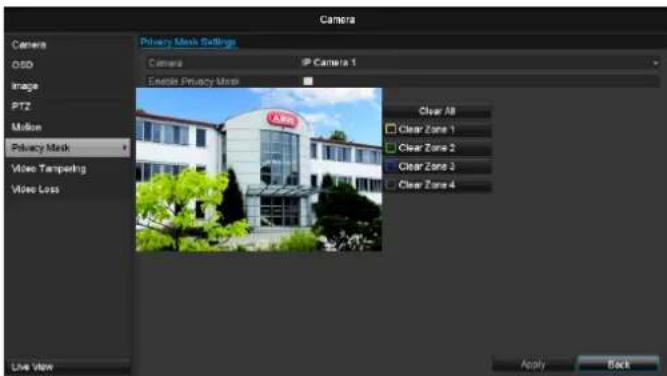
text_image
Camera Camera Mask Settings Camera Camera 1 Enable Privacy Mask Clear All Clear Zone 1 Clear Zone 2 Clear Zone 3 Clear Zone 4 Privacy Mask Video Tempensing Video Loss Live View Apply Back- Select up to four private zones with the mouse.
i
Note
You can define up to 8 time periods (each from 00:00 to 00:00). The times in the individual periods must not overlap.
-
Select Copy if the setting is to be applied for all cameras.
-
Confirm the settings by clicking Apply and exit the menu with OK.
Tamper monitoring
Select the camera channel under "Camera".
Select the checkbox for activating tamper monitoring.
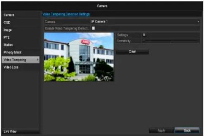
text_image
Camera Video Tampering Detection Settings Camera IP Camera 1 Enable Video Tampering Detection... Settings Sensitivity Clear Video Tampering Video Loss Live View Apply BackArmin Schedule
Select the TAB Arming Schedule.
Here you set the times when the reactions in the TAB Reaction are triggered.

text_image
Settings Trigger Channel Arming Schedule Linkage Action Week Mon 1 00:00-24:00 2 00:00-00:00 3 00:00-00:00 4 00:00-00:00 5 00:00-00:00 6 00:00-00:00 7 00:00-00:00 8 00:00-00:00 Copy Apply OK Cancel- Select the day and enter the schedule.

Note
You can define up to 8 time periods (each from 00:00 to 00:00). The times in the individual periods must not overlap.
- Select whether the settings should be applied to all days of the week with using Copy.
- Confirm the settings by clicking Apply and leave the menu with OK.
Handling
Click on the TAB Handling.
Here you can configure the behavior of the recorder during a detected event (for example: motion got detected) by clicking the respective check box.
text_image
Settings Trigger Channel Arming Schedule Linkage Action ■ Full Screen Monitoring ■ Audible Warning ■ Notify Surveillance Center ■ Send Email ■ Trigger Alarm Output Apply OK Cancel| Parameter | Notifications |
| Full-screen pop-up | The camera is displayed as a full-screen picture in live cast |
| Audible Warning | The device emits a repeating tone. |
| Notify CMS | The CMS emits an audible warning tone. |
| Send email | An email is sent to a specific email address. See page 29 |
| Trigger alarm output | The alarm output is triggered in the event of an alarm. |
- Confirm the settings by clicking Apply and leave the menu with OK
Video signal loss
Select the camera channel under "Camera".
Set the checkmark for the alarm in the event of a "Video Loss".
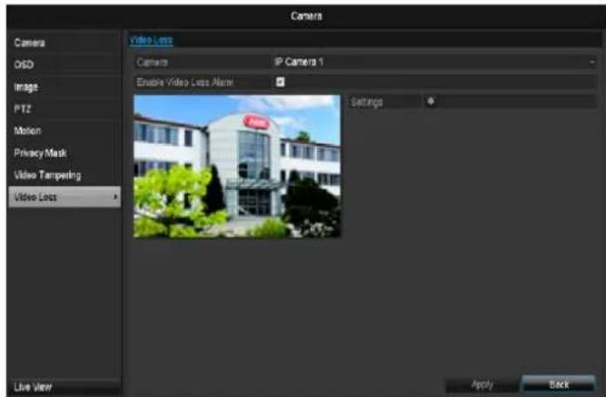
text_image
Camera Camera OSD Image PTZ Motion Privacy Mask Video Tampering Video Loss Live View Video Loss Camera IP Camera 1 Enable Video Loss Alert! Settings Apply BackArmin Schedule
Select the TAB Arming Schedule.
Here you set the times when the reactions in the TAB Reaction are triggered.
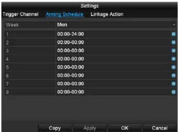
text_image
Settings Trigger Channel Arming Schedule Linkage Action Week Mon 1 00:00-24:00 2 00:00-00:00 3 00:00-00:00 4 00:00-00:00 5 00:00-00:00 6 00:00-00:00 7 00:00-00:00 8 00:00-00:00 Copy Apply OK Cancel- Select the day and enter the schedule.
i
Note
You can define up to 8 time periods (each from 00:00 to 00:00). The times in the individual periods must not overlap.
- Select whether the settings should be applied to all days of the week with using Copy.
- Confirm the settings by clicking Apply and leave the menu with OK.
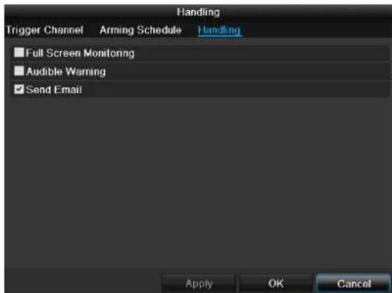
Handling
Click on the TAB Handling.
Here you can configure the behavior of the recorder during a detected event (for example: motion got detected) by clicking the respective check box.
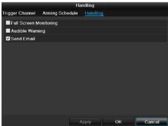
text_image
Handling Trigger Channel Arming Schedule Handling ■ Full Screen Monitoring ■ Audible Warning ✓ Send Email Apply OK Cancel| Parameter | Notifications |
| Full-screen pop-up | The camera is displayed as a full-screen picture in live cast |
| Audible Warning | The device emits a repeating tone. |
| Notify CMS | The CMS emits an audible warning tone. |
| Send email | An email is sent to a specific email address. See page 29 |
| Trigger alarm output | The alarm output is triggered in the event of an alarm. |
- Confirm the settings by clicking Apply and leave the menu with OK
Record
Setting up
Open the main menu and click on record:
Schedule
The schedule is used to specify the recording times and triggers (recording type) for the cameras. Click on the "Schedule" tab:

Note
Because there is no difference between the settings for the TABs record and instant image, these are only listed once.
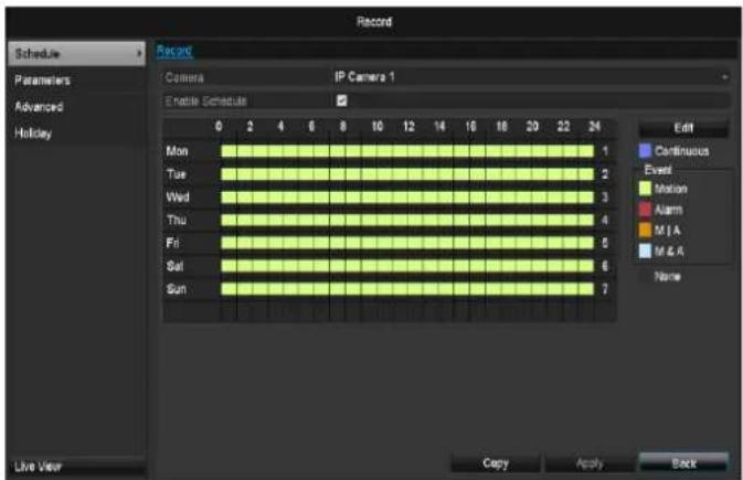
text_image
Record Camera IP Camera 1 Enable Schedule 0 2 4 6 8 10 12 14 16 18 20 22 24 Mon Tue Wed Thu Fri Sat Sun Edit Continuous Event Motion Alarm M & A M & A Name Live View Copy Apply BackIn the OSD, the hours of the respective days are listed from left to right (the days are listed from top to bottom). A colour key is shown underneath the days (i.e. the recording periods in the schedule are shown in colour according to the trigger (recording types).
| Colour symbol | Key |
| Blue | Normal recording: Period in hours |
| Yellow | Motion detection |
| Red | Alarm |
| Orange | Motion or alarm |
| Light blue | Motion and alarm |
| Grey | No selection |
| Brown | Motion or alarm |
- Select the camera and click on the check box Enable Schedule.
- Click on Edit to specify the type and duration of the time plan
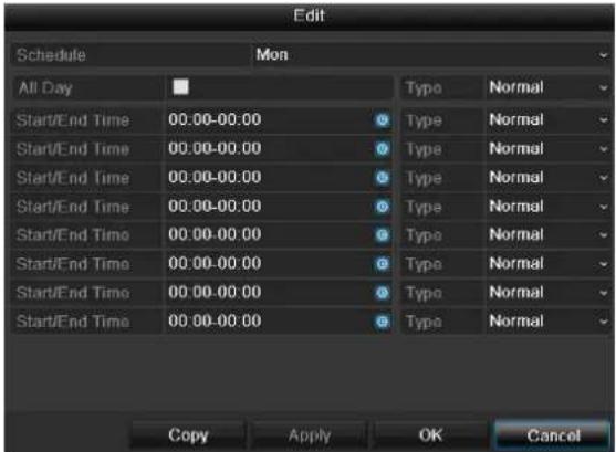
text_image
Edit Schedule Mon All Day Start/End Time 00:00-00:00 Type Normal Start/End Time 00:00-00:00 Type Normal Start/End Time 00:00-00:00 Type Normal Start/End Time 00:00-00:00 Type Normal Start/End Time 00:00-00:00 Type Normal Start/End Time 00:00-00:00 Type Normal Start/End Time Copy Apply OK Cancel- Define the day to be set in the pull-down menu at 'Schedule'.
- Activate/deactivate 'All day'. If the full day is active, no definite times can be entered as the setting is now valid for the whole day.
- To make specific time settings, deactivate the "All Day" box.

Application example
Recording should run from 11:00 to 07:00. 2 time zones must be set up for this:
-
11:00 AM - 24:00PM
-
00:00 AM - 7:00 AM
-
Specify the recording type in the drop-down menu:
-
Time
- Motion detection
-
Alarm
• Motion detection or alarm
• Motion detection and alarm -
When making a specific time setting, you can define up to 8 time periods (each from 00:00 to 24:00). The times in the individual periods must not overlap.

Note
The "Time" recording type defines the time window where a recording is made.
The other events (e.g. motion detection and/or alarm) only trigger the recording after the specific event has occurred.
- At Copy you can take on this setting for other days or the whole week.
- Finalize your settings in the record screen with Apply and then OK.
Encoding
Record
The schedule is used to specify the recording times and triggers (recording type) for the cameras.
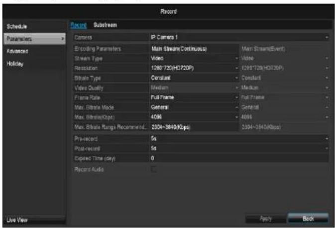
text_image
Record Schedule Parameters Advanced Holiday Live View Record Substream Camera IP Camera 1 Encoding Parameters Main Stream(Continuous) Main Stream(Event) Stream Type Video - Video Resolution 1280-720(HD720P) - 1280-720(HD720P) Bitrate Type Constant - Constant Video Quality Medium - Medium Frame Rate Full Frame - Full Frame Max. Bitrate Mode General - General Max. Bitrate(Kbps) 4096 - 4096 Max. Bitrate Range Recommendation 3504-3840(Kbps) 3304-3840(Kbps) Pre-record 5s Post-record 5s Expired Time (day) 0 Record Audio Apply BackThe following setting options are available in this sub-menu:
| Camera | Camera to be set |
| Encoding Parameter | Stream to be set |
| Stream Type | Predefined video stream |
| Resolution | Auto, WD1 (960x480)4CIF (704x576),2CIF (704 x 288), CIF (352x288), QCIF (176x144) |
| Bit rate | Select a variable or constant bit rate |
| Video Quality | There are various quality levels:+++: medium quality+++++: high quality |
| Frame rate | Setting for the stream frame rate |
| Max. bit rate mode | Select the mode for setting the bit rateUser def. (32 – 3072) |
| Max. bit rate (kbps) | Setting for the maximum bit rate |
| Recommended max. bit rate | Recommended bit rate depending on the set resolution, frame rate, etc. |
| Record audio | Activated:Recording with audio data |
Confirm the settings by clicking Apply and exit the menu with OK.
TAB Substream
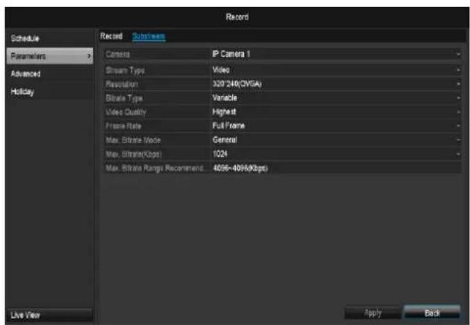
text_image
Record Schedule Parameters Advanced Holiday Live View Record Substream Camera IP Camera 1 Stream Type Video Resolution 320'240(OVGA) Bitrate Type Variable Video Quality Highest Frame Rate Full Frame Max. Bitrate Mode General Max. Bitrate("Ops) 1024 Max. Bitrate Range Recommendation 4096-409%(Kbps) Apply BackThe following parameters can be set:
| Camera | Camera to be set |
| Stream Type | Predefined video stream |
| Resolution | Auto, 4CIF (704x576), CIF (352x288), QCIF (176x144) |
| Bit Rate Type | Select a variable or constant bit rate |
| Video Quality | There are various quality levels: +++: medium quality+++++: high quality |
| Frame rate | Setting for the stream frame rate |
| Max. bit rate mode | General, user def. (32 – 3072 |
| Max. bit rate (kbps) | Display of the maximum bit rate |
| Recommended max. bit rate | 192~320 (kbps) |
Confirm the settings by clicking Apply and exit the menu with Back.
| Lead time | Recording period before an alarm (in seconds) |
| Overrun time | Recording period after an alarm (in seconds) |
| Mark elapsed time | Setting for the longest retention time for recorded files. |
Advanced settings
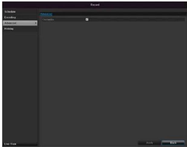
text_image
Record Schedule Encoding Advanced Holiday Advanced Descriptive Live View Audio Back| Overwrite | You can specify whether older recordings are deleted when the HDD memory is full |
Holidays
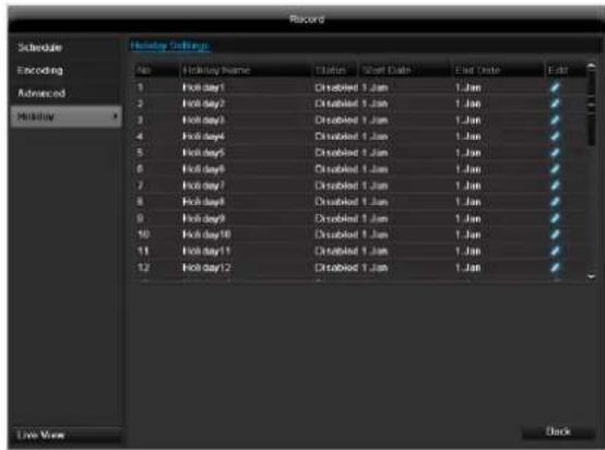
text_image
Record Schedule Encoding Advanced Holiday Holiday Settings No.Holiday Name Status Short Date End Date Edit 1 Fall day1 Disabled 1 Jam 1.Jan ✓ 2 Fall day2 Disabled 1 Jam 1.Jan ✓ 3 Fall day3 Disabled 1 Jam 1.Jan ✓ 4 Fall day4 Disabled 1 Jam 1.Jan ✓ 5 Fall day5 Disabled 1 Jam 1.Jan ✓ 6 Fall day6 Disabled 1 Jam 1.Jan ✓ 7 Fall day7 Disabled 1 Jam 1.Jan ✓ 8 Fall day8 Disabled 1 Jam 1.Jan ✓ 9 Fall day9 Disabled 1 Jam 1.Jan ✓ 10 Fall day10 Disabled 1 Jam 1.Jan ✓ 11 Fall day11 Disabled 1 Jam 1.Jan ✓ 12 Fall day12 Disabled 1 Jam 1.Jan ✓ Live Now DockIn this sub-menu, 32 different recording settings for vacations or public holidays can be applied. To apply these settings click on the "Edit" symbol:
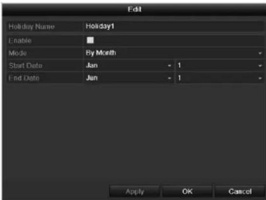
text_image
Edit Holiday Name Holiday1 Enable Mode By Month Start Date Jan - 1 End Date Jan - 1 Apply OK Cancel| Holiday Name | Manual name entry of the vacation or holiday |
| Enable | Activate or deactivate the set vacation |
| Mode | According to date / week / month |
| Start Date | Selection of start date / start time |
| End Date | Selection of end date / end time |
Confirm your settings with Apply and OK.
HDD
HDDs

Note
The device can manage one 2.5" SATA hard disk drive.
Each of the installed HDDs must be initialised before the device can be used for recording. The device only detects the HDD and its assignment after initialisation has been made.

Warning
All data is deleted from the HDD during initialisation.
Ensure a data backup has been made in good time beforehand.
Installing the HDD
- Disconnect the device from the mains power and open the cover.
- Observe the applicable ESD guidelines when handling electronic devices and ensure they are earthed.
- Do not open the device in rooms with carpets or other surfaces that can become electro statically charged.
- Avoid bodily contact with all components on the PCB.

Warning
If you have questions regarding the information or cannot find the information you need, please contact your maintenance specialist.
- Install the HDD and then connect it.
- Reattach the cover and connect the device to the mains power supply.

Note
If the initialised HDD is not displayed, check the connections
Click on "HDD" in the menu to define settings relating to hard disc administration
HDD Management parameters
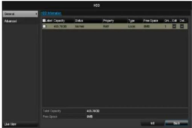
text_image
HDD General Advanced HDD Information Label Capacity Status Property Type Free Space Gro... Edit Del... 1 465.76GB Norms RAW Local BME 1 Total Capacity 465.76GB Free Space BME Live View Init Back| HDD information | |
| No. | Shows the internal connection number |
| Capacity | HDD capacity (in GB) |
| Status | Shows the current status of the HDD:Not initialisedNormalErrorStandby |
| Features | Read-only: Read-only protectionR/W: Read and write |
| Type | Local: Device HDDNFS: Network HDDIf possible, avoid using NFS storage due to compatibility problems that may occur. |
| Free Space | Shows the approximate free memory for recordings |
| Delete | Remove the hard drive |
- Select the HDD by ticking the corresponding box.
- Start the process by clicking on Init.
- Confirm the prompt by pressing OK.
- The status bar shows the progress of the initialisation.
- After finishing the process the HDD appears.
HDD settings of the cameras
Click on the "Advanced" submenu
Mode: Storage
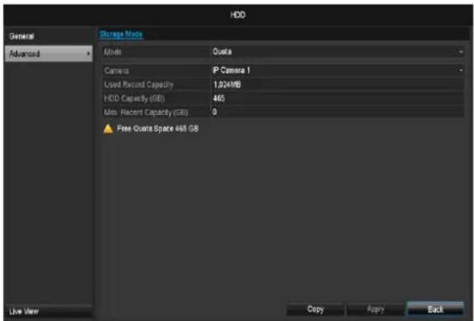
text_image
HDD General Advanced Storage Mode Mode Quota Camera P Camera 1 Used Record Capacity 1.024MB HDD Capacity (GB) 465 Max Recent Capacity (GB) 0 Free Quota Space 465 GB Copy Copy Back Live View| Camer | Auswahl des zu bearbeitenden Kamerakanals |
| Used record capacity | Size for recording file |
| HDD Capacity (GB) | HDD capacity (in GB) |
| Max. Capacity (GB) for recording | Define the maximum recording size for a camera on the HDD. |
- Select Copy if the setting is to be applied for all cameras.
- Confirm the settings by clicking Apply and exit the menu with OK.
- Click Apply and confirm the restart in the next window with OK.
- To do this, call "Warning" in the "Settings" menu.
Panic recording
Recording
Press the REC button or navigate to Panic Recording in the main menu to start manual picture/video recording.
Click on the "Recording" submenu.
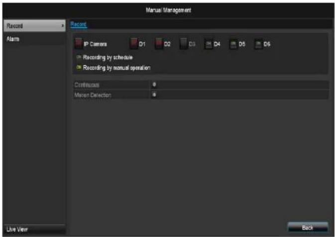
text_image
Record Alarm Record IP Camera D1 D2 D3 D4 D5 D6 Recording by schedule Recording by manual operation Continuous Motion Detection Live View Back| Analog | Select the settings for all camerasClick “Off” or “On” to change the settings.On, green:Recording according to schedule,On, yellow:Recording with manual operationOff, red:No recording. |
| Duration | Click on permanent recording to activate all channels for the whole day.Click “Yes” to confirm your selection. |
| Motion detection | Click the symbol to activate motion detection for all channels for the whole day.Click “Yes” to confirm your selection. |
Alarm
Select the alarm output here which should be switched for a panic recording.
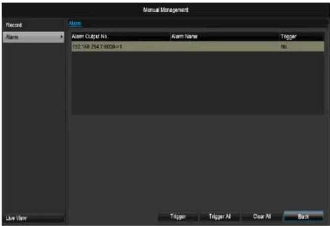
text_image
Manual Management Record Alarm Alarm Alarm Output No. Alarm Name Trigger 192.168.254 7-8009->1 No Live View Trigger Trigger All Clear All BackYou can switch several alarm outputs for a panic reaction.
Select Trigger to activate the selected alarm output.
Click Trigger all to activate all alarm outputs.
Click Delete all to remove the settings.
Video Export
Duration
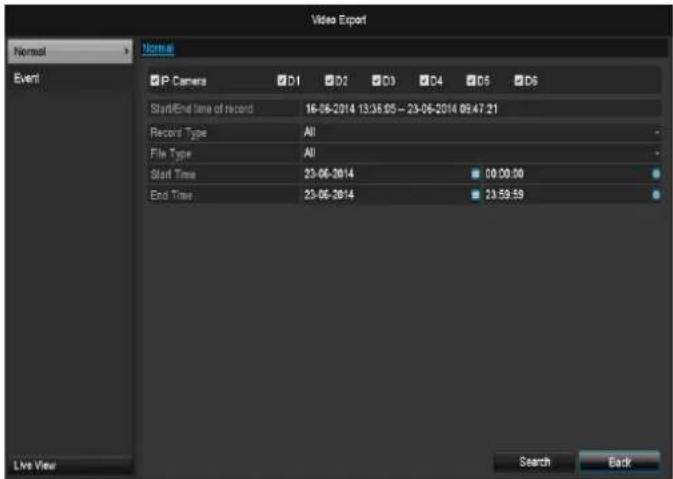
text_image
Video Export Normal Event IP Camera D1 D2 D3 D4 D5 D6 Start/End Time of record 16-06-2014 13:36.05 - 23-06-2014 09:47:21 Recent Type All File Type All Start Time 23-06-2014 00:00:00 End Time 23-06-2014 23:59:59 Live View Search Backi
Note
The export function is used to store important recordings on connected external media, such as:
- USB media
- USB HDD
- DVD writer
- When "Quick export" is selected, all recordings of the selected time span are exported. Please note that not more than 24 hours can be exported.
- Enter the parameters.
- Click on "Details" to limit the search
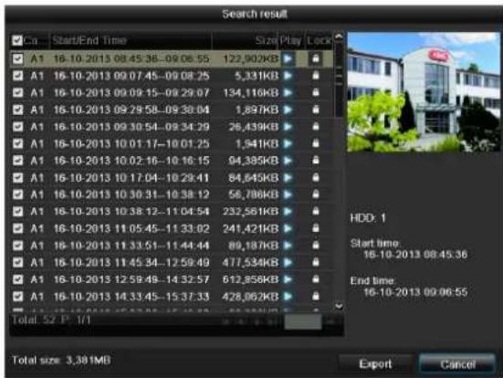
text_image
Search result ✓ Co Start/End Time Size/Play/Lock ✓ A1 16-10-2013 08:45:36-09:06:55 122,902KB ✓ A1 16-10-2013 09:07:45-09:08:25 5,331KB ✓ A1 16-10-2013 09:09:15-09:29:07 134,116KB ✓ A1 16-10-2013 09:29:58-09:38:04 1,897KB ✓ A1 16-10-2013 09:30:54-09:34:29 26,439KB ✓ A1 16-10-2013 10:01:17-10:01:25 1,941KB ✓ A1 16-10-2013 10:02:16-10:16:15 94,389KB ✓ A1 16-10-2013 10:17:04-10:29:41 84,645KB ✓ A1 16-10-2013 10:30:31-10:38:12 56,786KB ✓ A1 16-10-2013 10:38:12-11:04:54 232,561KB ✓ A1 16-10-2013 11:05:45-11:33:02 241,421KB ✓ A1 16-10-2013 11:33:51-11:44:44 89,187KB ✓ A1 16-10-2013 11:45:34-12:59:49 477,534KB ✓ A1 16-10-2013 12:59:49-14:32:57 612,856KB ✓ A1 16-10-2013 14:33:45-15:37:33 428,062KB Total 52 P 7/7 Total size: 3.38MB Export Cancel HDD: 1 Start time: 16-10-2013 08:45:36 End time: 16-10-2013 09:06:55- The file size of the individual recording and the total size of all found recordings are displayed.
- By clicking the "Playback" symbol you can view the respective recording.
-
To block or unblock a file click on the "Lock" symbol.
-
Click on Export to access the export screen.
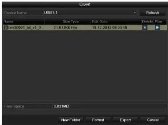
text_image
Export Device Name USB1.1 Refresh Name Size Type Edit Date Delete Play twr30004_int_v1_0 21.671KB File 18.10.7913 09:30:48 Free Space 3.831MB New Folder Format Export Cancel- Select the connected medium used for data storage from the drop-down menu.
- If the medium is not displayed, click on Refresh.
- If the medium is still not displayed, disconnect it from the device and reconnect the medium again. See also the manufacturer's specifications.
- Click on Export to start the export process. The progress of the export process is then displayed.
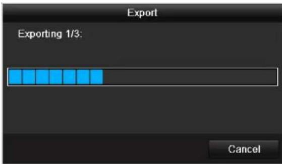
text_image
Export Exporting 1/3: Canceli
Note
After the storage process is completed, the data on the medium can be selected and played on the player (which was also backed up). In this way, you can check whether the export has been made successfully.
Event (event type 'Motion')
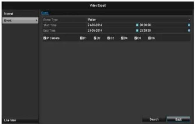
text_image
Video Export Event Event Type Motion Start Time 23-06-2014 09:00:00 End Time 23-06-2014 23:58:59 IP Camera D1 D2 D3 D4 D5 D6 Live View Search BackDefine the time span of the recording being searched for by means of the selection fields at "Start time" and "End time". Select the camera by activating or deactivating the check box and click Search.
For both types of event, the following window appears after activating the Search button:
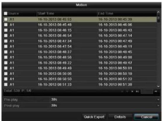
text_image
Motion Source Start Time End Time A1 16-10-2013 08:45:03 16-10-2013 08:45:39 A1 16-10-2013 08:45:48 16-10-2013 08:46:06 A1 16-10-2013 08:46:15 16-10-2013 08:46:43 A1 16-10-2013 08:46:54 16-10-2013 08:47:14 A1 16-10-2013 08:47:34 16-10-2013 08:47:49 A1 16-10-2013 08:47:54 16-10-2013 08:48:11 A1 16-10-2013 08:48:37 16-10-2013 08:48:45 A1 16-10-2013 08:48:56 16-10-2013 08:49:08 A1 16-10-2013 08:49:22 16-10-2013 08:49:47 A1 16-10-2013 08:49:49 16-10-2013 08:50:01 A1 16-10-2013 08:50:06 16-10-2013 08:50:19 A1 16-10-2013 08:50:50 16-10-2013 08:51:22 A1 16-10-2013 08:51:23 16-10-2013 08:51:38 Total: 539 P. 1/6 Pre-play 30s Post-play 30s Quick Export Details CancelSelect the files to be exported by activating or deactivating the check box. You can set the pre-alarm and post-alarm time at "Pre-play" or "Post-play". In this way you can define the length of your export video.
Click on Details to view the selected video. For more exact information on the Details window, see DURATION (p. Fehler! Textmarke nicht definiert.).
i
Note
The "Pre-play" recordings can only be viewed when recording has been carried out before the alarm.
i
Note
The sub-menus "Normal" and "Picture" are similar and are therefore not listed separately.
Maintenance

Note
This menu is used for device maintenance, and should only be operated by experienced users.
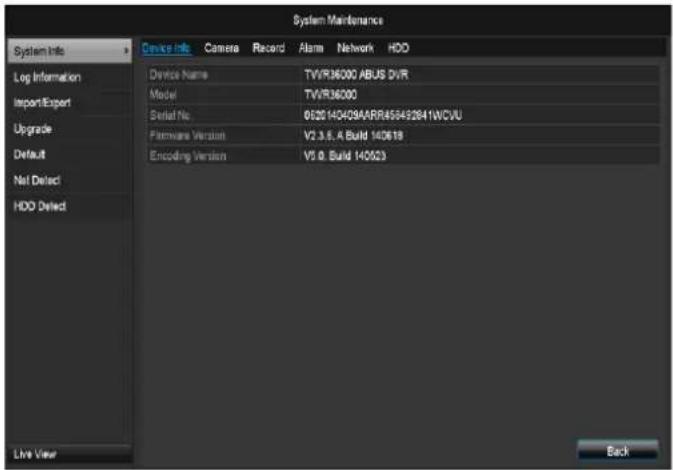
text_image
System Maintenance System Info Log Information Import/Export Upgrade Default Net Detect HDD Detect Device Info Camera Record Alarm Network HDD Device Name TVIR36000 ABUS DVR Model TVIR36000 Serial No 0520 140429AARR458452841WCVU Permissive Version V2.3.5, A Build 140618 Encoding Version V5.0, Build 140523 Live View Back| Menu | Setting | P. |
| System Info | Device information (serial number, firmware status etc.) | 103 |
| Log Search | A search of recordings or information (S.M.A.R.T. HDD status) can be made in the log file according to certain criteria (alarms, exceptions, operation or information). | 103 |
| Import/Export | Used to export or import the settings | 104 |
| Upgrade | Carries out a firmware upgrade | 104 |
| Default | System reset | 105 |
| Network | Displays the transmission and reception rate of the recorder | 105 |
| S.M.A.R.T | Hard disk drive test for errors | 49 |
System Info
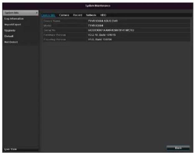
text_image
System Maintenance System info Log Information Import/Export Upgrade Default Not Default Device Name: TVRSX004 ARLS DVR Model: TVRSX004 Serial No: 040818801AAW642891914WCVU Functional Person: ¥2.2.19, D204 138015 Floating Person: ¥5.0, D40 138016 Live Time Back
Note
The information menu shows the technical data for the device and information on the various settings of the cameras, recording, alarm, network and HDD.
This can be useful for support queries, for example.
Log Search
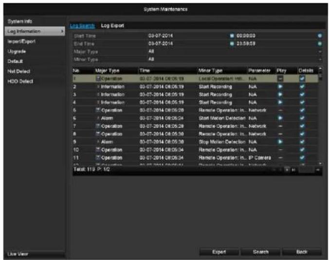
text_image
System Maintenance Log Search Log Export Start Time 03-07-2014 09:30:59 End Time 03-07-2014 23:30:59 Major Type All Minor Type All No Major Type Time Minor Type Parameter Play Details 1 Operation 03-07-2014 08:06:19 Local Operation In... N/A 2 Information 03-07-2014 08:05:19 Start Recording N/A 3 Information 03-07-2014 08:05:19 Start Recording N/A 4 Information 03-07-2014 08:05:19 Seed Recording N/A 5 Operation 03-07-2014 08:05:29 Remote Operation In... Network 6 Alarm 03-07-2014 08:05:24 Start Motion Detection N/A 7 Operation 03-07-2014 08:05:29 Remote Operation In... Network 8 Operation 03-07-2014 08:05:30 Remote Operation In... Network 9 Alarm 03-07-2014 08:05:30 Stop Motion Detection N/A 10 Operation 03-07-2014 08:05:34 Remote Operation In... N/A 11 Operation 03-07-2014 08:05:34 Remote Operation In... IP Camera Total: 113 P. 12 Export Search Back
Note
An event search can be made according to the following main types, events and parameters:
• All
- Alarm
- Exception
- Operation
• Information
| Filter1 | Filter2 |
| All | - |
| Alarm | AllAlarm Input/OutputStart/Stop Motion DetectionStart/Stop Tamper-proof |
| Exception | AllVideo Loss SignalVideo Signal ExceptionIllegal LoginHDD FullHDD ErrorIP ConflictedNetwork DisconnectedException recordingVideo input/output signal not equalRecorder buffer overflow |
| Operation | AllPower OnAbnormal ShutdownStart/Stop AudioLocal Operation, e.g.:Shutdown/Reboot/Login/Logout/Configure Parameters/Upgrade/Start RecordingRemote Operation, e.g.:Export Record File/Alarm Arming/ ... |
| Information | AllLocal HDD InformationHDD S.M.A.R.T.Start/Stop RecordingStart/Stop CaptureDelete Expired RecordNetHDD Information |
- Select the event you wish to search for in the log, then select the sub-parameter.
- Enter the date and time under "Start Time" and "End Time", then click on Search.
- The results are then displayed:
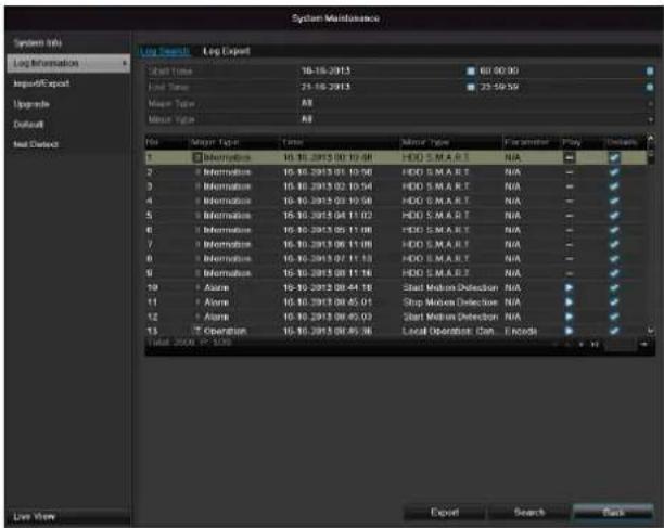
text_image
System Maintenance System Info Log Information Import/Export Upgrade Default Set Out Log Search Log Export Start Time 16:16:2013 60:00:00 End Time 21:16:2013 23:59:59 Major Type All Minor Type All No Major Type Times Minor Type Parameters Play Details 1 Description 15:16:2013 00:10:48 HDD S.M.A.R.T N/A 2 Information 15:16:2013 01:10:46 HDD S.M.A.R.T N/A 3 Information 15:16:2013 02:10:54 HDD S.M.A.R.T N/A 4 Information 15:16:2013 03:10:58 HDD S.M.A.R.T N/A 5 Information 15:16:2013 04:11:02 HDD S.M.A.R.T N/A 6 Information 15:16:2013 05:11:08 HDD S.M.A.R.T N/A 7 Information 15:16:2013 06:11:08 HDD S.M.A.R.T N/A 8 Information 15:16:2013 07:11:13 HDD S.M.A.R.T N/A 9 Information 15:16:2013 08:11:16 HDD S.M.A.R.T N/A 10 Asame 15:16:2013 08:44:18 Start Motion Detection N/A 11 Asame 15:16:2013 08:45:01 Stop Motion Detection N/A 12 Asame 15:16:2013 08:45:03 Start Motion Detection N/A 13 Operation 15:16:2013 08:45:36 Local Operation Can Encodes Total 2009 PC-528 Export Search Run- The pages are changed using the navigation bar:

(1) (2)
(3) (4)
(5)
(6)
i Note
To scroll forwards or backwards press (3) or (2). To jump to the first or last page press (4) or (1). To go to a specific page number enter it in (5) and confirm by clicking (6).
- Click on Details to see more detailed information.
- Click on Play to start the recording for the event, when necessary.
- Click on Export to back up the log file on a USB medium.
Import / Export
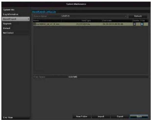
text_image
System Maintenance System Info Log Information ImportExport Upgrade Default Net Default ImportExport Cable File Device Name: USB1.0 Source: Smart Type: Fast Data Schedule: Play Smart8004.txt, w1_9_psc 21.321457 files 16.10-2012.09.20.46 Free Scope: 3.03 MB New Folder Import Export Backi
Note
The configuration data contains all settings made on the device since the start of operation. This data can be saved on a USB medium. You can then configure another device identically, for example.
Upgrade
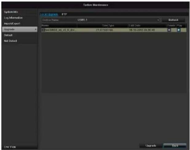
text_image
System Mastercard System Info Log Information Report/Export Upgrade Default Not Default Local System FTP Custom Name: USB1.1 Form Size Type Lot Date Delete Play [Swc30001_at_v1_6_doc..] 71.01162 Files 18.10-2013 00:30:49 Upgrade Exiti
Note
A device upgrade can be made from a USB device or over the network via FTP.
- Copy the upgrade file to the main directory of a USB stick.
-
Connect the USB stick to a USB port on the device.
-
Select the USB port (click on Refresh, if necessary).
- Select the upgrade file and click on Upgrade.
- Wait until the device reboots.
- Check the firmware status in the "Maintenance" menu under "System Info".
i
Note
Upgrades via FTP are made in the same way as detailed above.
The PC must be in the same local network.
Set up a PC as an FTP server.
Enter the IP address of the FTP server.
Default
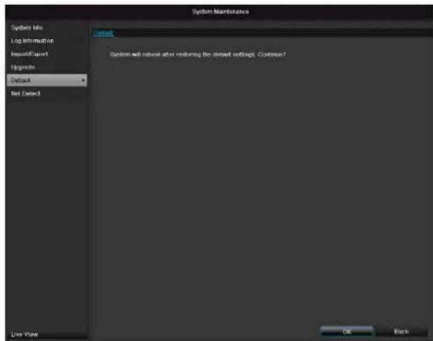
text_image
System Maintenance System info Log information Import/Export Upgrade Default Net Default Default System will robust after reducing the dbroot settings. Continue? Live View OK Backi
Note
In this process, the device is reset to the factory default settings.

Warning
All settings made since the start of operation are deleted (cameras, recording settings, alarms etc.)!
Avoid data loss by backing up the settings in advance. These can be imported again following the system reset.
Network
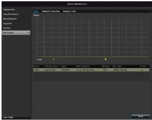
text_image
System Maintenance Network Detection Networks Status 100bps LANT Name: Linking Status Type MAC Attacks MTU/CH NC Type TATE LANT Successful Extended 0x 7.49 26-bit 8A 1000 244M Full-Disp End View Backi
Note
Information regarding the network traffic and network interfaces are shown here.
TAB network load
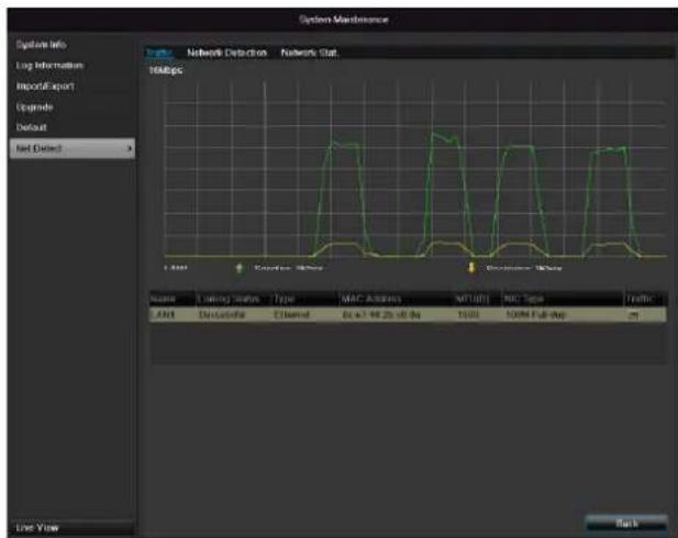
text_image
System Maintenance Network Detection Networks Stat 10Mbps LAM Continuous Noise Continuous Noise Line View Line Info Log Information Import/Export Upgrade Default Net Dated LAN Timing Status Type MAC Address MT101 NDC Type Traffic LAN Continuous Channel 0x+7.46.2x-0.8x 15:00 100% Full-Up RunThe amount of received and sent data is displayed graphically.
Depending on the network settings, the status and information for one or two network connections is shown in the field underneath the graph.
TAB Network Detection
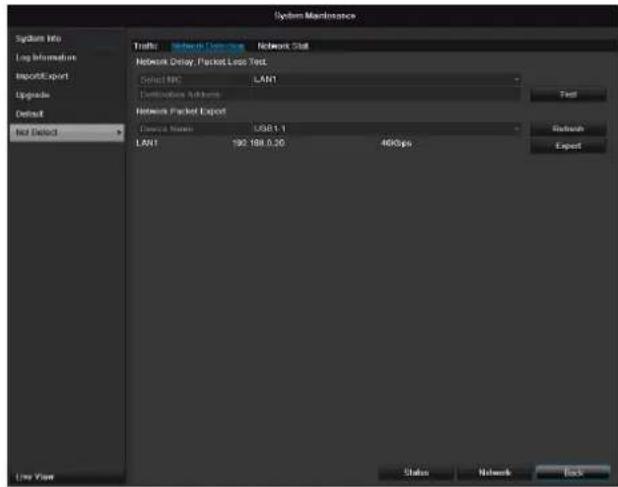
text_image
System Maintenance Systall Data Log Information Report/Export Upgrade Default Net Defect Results Network Data Network Stat Network Delay / Packet Loss Test Ducts IPC LAN1 Contributions Additions Network Packet Export Device Name USB1.1 LAN1 192 188.0.30 460bps Test Refresh Export Live View Status Network BackIn "Destination Address", you can check the connection to another device, such as a computer ('pinging'). Enter the network address of the device to be checked (e.g. 192.168.0.25) and press Test.
Information on two parameters appears:
| Parameter | Setting |
| Average delay | The time the pinged device needs to reply. |
| Packet loss Rate: | Displays the percentage of packets that were not transmitted |
i
Note
If the packet loss rate is high, we recommend that the "Network Test" is repeated.
i
Note
If the packet loss rate is still high, you should check that the cables are correct and not damaged.
The higher the packet loss rate, the poorer the connection between the pinged device and recorder.
For "Network Packet Export", you can export the settings of the individual connections or – depending on the setting – the connection.
-
For "Device Name", select a storage medium to save the settings to.
-
Click Export.

text_image
Packet exporting CancelAfter the progress display finishes and initialization is successful, an information window appears. Close it with OK.
- Click Status to display the status of the LAN connections (connected/not connected).
- Click Network to change your network settings (see p.84).
TAB Network Stat.
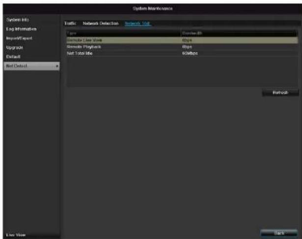
text_image
System Maintenance System Info Log Information Import/Export Upgrade Default Net Default Traffic Network Detection Network Slot Name Standard Template Live Voice 8bps Remote Playback 8bps Net Total Site 60Mbps Refresh Live Voice BackDisplays all used in- and outcoming bandwidth.
You can refresh the data by clicking on Refresh.
S.M.A.R.T
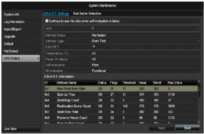
text_image
System Maintenance System Info Log Information Import/Export Upgrade Default Net Delted HDD Delted S.M.A.R.T. Settings Bad Sector Detection ■ Continue to use this disk when self-evaluation is failed. HDD 1 Self-test Status Not tested Self-test Type Short Test S.M.A.R.T. 0 Temperature (°C) 40 Power On(days) 48 Self-evaluation Pass All-evaluation Functional S.M.A.R.T. Information ID Attribute Name Status Flags Threshold Value Worst Raw Value 0x1 Raw Read Error Rate OK 29 51 280 200 0 0x3 Spin Up Time OK 27 21 157 153 1150 0x4 Start/Stop Count OK 32 0 100 100 37 0x5 Reallocated Sector Count OK 33 140 176 178 1050 0x7 Seek Error Rate OK 2e 0 200 200 332 0x9 Power-on Hours Count OK 32 0 99 99 1133 Free Spin On Data Count OK 32 0 100 963 0 Apply BackClick on the "S.M.A.R.T" submenu.
In this submenu, you have the option to check your hard disk drive for errors.
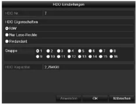
text_image
HDD Einstellungen HDD Nr 7 HDD Eigenschaften ● RW ● Nur Lese-Rechte ● Redundant Gruppo 1 2 3 4 5 6 7 8 9 10 11 12 13 14 15 16 HDD Kapazital 2,794GB Anwenden OK Abbrevchen| HDD | Selection of the hard disk drive to be processed. |
| Self-test status | Shows the status of the current self-test |
| Self-test type | Select the type of the self-test.Short Test / Expanded Test / Transport Test |
| .M.A.R.T | Click on the icon to start the self-test |
| Temperature (°C) | Display the HDD temperature |
| Switching on (Days) | Display the operating days of the hard disk drive |
| Self-evaluation | Status display of the self-evaluation |
| Complete evaluation | Status display of the evaluation |
Confirm the settings by clicking Apply and exit the menu with OK.

Note:
If only one HDD is installed and this is set to "Read-only", then the device cannot make recordings.
Checking the hard disk drive status
The status of each HDD can be checked in the “Maintenance” menu. S.M.A.R.T. information (Self-Monitoring, Analysis and Reporting Technology) is stored in the log data.
- Open the log file and search according to the information/S.M.A.R.T. Hard Disk Drive. Setting up the hard disk drive alarms
- You can specify alarms to inform you of HDD errors. To do this, call "Warning" in the "Settings" menu.
Shutdown
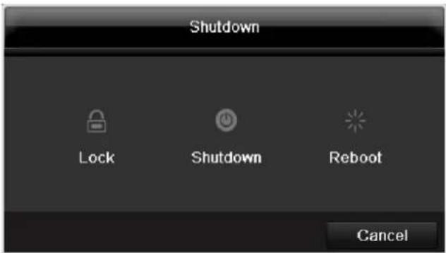
text_image
Shutdown Lock Shutdown Reboot Canceli
Note
- Select "Lock" to lock the operating menu.
- Select "Shutdown" to switch off the device.
- Select "Reboot" to reboot the system (switch off and back on).
Display
i
Note
See description on page 75.
Settings: Recording
i
Note
See description on page 94.
Settings: Network
i
Note
See description on page 84.
Troubleshooting
Before calling the Service department, read the following information to determine the possible cause of a malfunction.
| Malfunction | Cause | Solution |
| No power | Mains cable not connected | Connect the mains cable securely to the socket |
| Power switch set to OFF | Turn the power switch to ON | |
| No current in the power socket | Use another device on the socket, where necessary | |
| No image | Screen not set for reception | Set the correct video input mode until an image from the recorder appears |
| Video cable not connected properly | Connect the video cable securely | |
| Connected modem is switched off | Switch on the monitor | |
| No sound | Audio cables not connected properly | Connect the audio cables securely |
| Devices connected over the audio cables are not switched on | Switch on the devices connected over the audio cables | |
| Audio connection cable is damaged | Replace the cable | |
| HDD is not working | Connection cables not connected properly | Connect the cables securely |
| HDD defective or not system-compatible | Replace with a recommended HDD | |
| USB port not working | Device not supported | Connect a compatible USB medium (USB 2.0) |
| USB hub is in use | Connect the USB medium directly | |
| Network access not possible | Network cable connections are loose | Connect the network cable |
| Network settings are incorrect (DHCP, IP address etc.) | Check the network configuration and cor-rect it, ifnecessary (see page 89). | |
| Remote control is not working | Batteries inserted with the wrong polarity or are empty | Replace the batteries. To control the device with the remote control, point it at the remote control sensor on the device |
| Remote control too far away from the re-corder | Use the remote controller within 7 metres from the device | |
| Signal blocked by obstruction between the remote control and recorder | Remove the obstruction | |
| Lighting too bright or fluorescent tubes in use? | Switch off strong fluorescent lighting in the immediate vicinity | |
| Recording not possible | No HDD or HDD is not initialised | Install and initialise the HDD |
| Sudden deactivation of the device | Temperature inside the device is too high | Clean the device and remove any obstructions from the ventilation area |
Device cleaning and care
Note
- Your device requires no maintenance.
- Protect the device from dust, dirt and moisture.
Technical data
Subject is to alterations and errors. The dimensions are approximate values.
| ABUS digital recorder | TVVR36000 |
| Video compression | H.264 |
| Camera inputs | 6 (4x PoE + 2x IP) |
| Monitor outputs | 1 x VGA, 1 x HDMI |
| Operating mode | Triplex |
| Resolution (live view) | VGA:1080P: 1920*1080/60 Hz, 1280*1024/60 Hz,720P: 1280*720/60 Hz, 1024*768/60 Hz |
| Resolution @ frame rate per camera (recording) | WD1, 4CIF, 2CIF, CIF, QCIF @ 25 fps |
| Total frame rate | 100 fps |
| Compression levels | 6 |
| Post-alarm memory | 0–30 sec. / 5–900 sec. |
| Storage medium | 1 x 2.5" SATA HDD |
| Data backup | 1 x USB 2.0 |
| Views | 1 / 2 / 4 |
| Recording modes | Manual, schedule, motion detection, alarm |
| Search modes | By event, date and time, S.M.A.R.T. |
| User levels | 2 (max. 31 users) |
| Network access | 1 x RJ45 10/100 Mbps |
| Parallel network access | 128 camera connections |
| Network functions | Live view, playback, data export |
| DDNS | √ |
| NTP | √ |
| Alarms | Acoustic warning, OSD signal, e-mail |
| Control | USB mouse |
| OSD languages | German, English, French, Dutch, Danish,Italian, Polish, Spanish, Swedish, Russian |
| Power supply | 48 VDC, 1,5 A, 50~60 Hz |
| Power consumption | <10 W (without HDD and PoE power supply) |
| Operating temperature | -10 °C ~ +55 °C |
| Dimensions (W x H x D) | 200 x 45 x 200 mm |
| Weight | ≤ 0.8 kg (without HDD) |
| Certifications | CE |
HDD storage capacity
In addition to the actual storage capacity of the installed HDD, the required storage space for recording and surveillance depends on the set resolution and frame rate of the recording.
On the included CD you can find a program in order to calculate the required amount of memory. In addition you find this software for download on our homepage.
Overview monitor output combination
It is possible to connect a SPOT monitor. Use the table below to find out what combinations are possible. A tick indicates that the combination is possible, a cross shows that it is not.
| VGA+HDMI | VGAonly | HDMIonly |
| √ | √ | √ |
Disposal
Information on the EU directive on waste electrical and electronic equipment
To protect the environment, do not dispose of the device with domestic waste at the end of its service life. It can be disposed of at one of the appropriate collection points in your country. Please obey your local regulations when disposing of material.

Dispose of the device in accordance with EU directive 2002/96/EC – WEEE (Waste Electrical and Electronic Equipment). If you have any questions, please contact the department of your local authority which is responsible for waste disposal. Used equipment can be disposed of, for example, by your local or municipal authority, the local waste disposal company or your dealer.
Information on handling batteries
- Always insert batteries with the correct polarity. Never attempt to recharge the batteries supplied and do not throw them into naked flames under any circumstances. Do not use different batteries at the same time (old and new, alkaline and zinc-carbon etc.). Remove the batteries if the device is not used for a long period of time. If used improperly, there is a risk of explosion and leaking batteries!
- Take environmental protection into account – used batteries should not be disposed of in domestic waste! They must be taken to a collection point for used batteries.
- Make sure that batteries are kept away from small children. Children may put batteries in their mouths and swallow them. This can cause serious harm to their health. If this happens, consult a doctor immediately.
- Do not charge normal batteries, heat them up or throw them into naked flames (they may explode).
- Change low batteries in good time.
- Always change all the batteries at the same time and use batteries of the same type.

Important
Leaky or damaged batteries can cause chemical burns on contact with the skin.
▶ In this case, wear protective gloves.
▶ Clean the battery compartment with a dry cloth.
Important information on disposing of batteries
Your product uses batteries which are subject to the European directive 2006/66/EC and may not be disposed of with domestic waste.
Find out about the regulations for the separate collection of batteries which apply in your country.
Proper disposal of batteries helps prevent harm to health and the environment.
Batteries that contain harmful chemicals are labelled with these signs:
Pb = battery contains lead
Cd = battery contains cadmium
Hg = battery contains mercury
Information on the European RoHS directive
The device complies with the RoHS directive.
Compliance with the RoHS directive means that the product or component does not contain more than the following maximum concentrations of the following substances in homogeneous materials, unless the substance is part of an application that is excluded from the RoHS directive:
a) 0.1% lead (by weight)
b) Mercury
c) Hexavalent chromium
d) Polybrominated biphenyl (PBB) and polybrominated diphenyl ether
e) 0.01% cadmium (by weight)
Glossary
Overview of specialist terms
1080i
HDTV image signal with 1080 pixels and interlaced display.
16:9
Cinematographic aspect ratio on widescreen displays.
720p
HDTV image signal with 1280 x 720 pixels and progressive display.
CIF
Common Intermediate Format
Originally planned for converting PAL to the NTSC standard. CIF corresponds to a video resolution of 352 x 288 pixels (2CIF = 704 x 288 pixels; 4CIF = 704 x 576 pixels).
CINCH
Socket type used for analogue audio or CVBS video signals.
CVBS
Colour, Video, Blank and Sync – The simplest variation of video signals (also known as composite video). The image quality is comparatively low.
DDNS
Dynamic Domain Name System entry
Network service which provides and updates IP addresses of its clients in a database.
DHCP
Dynamic Host Configuration Protocol
Network protocol which allows the automatic connection of devices (clients) in existing networks. DHCP servers (e.g. Internet routers) automatically assign the IP address, network mask, gateway, DNS server and WINS server (when required). Only the automatic acquisition of IP addresses must be activated for the client in this case.
Domain
Name used for the identification of websites on the Internet (e.g. www.abus-sc.de).
Dual Stream
Dual stream is a video transmission method. A high-resolution recording and lower-resolution transmission are made over the network, for example. The main stream has a 4CIF resolution and the sub-stream has a CIF resolution.
DVR
Digital Video Recorder – A device used for recording different video and audio sources (analogue, digital). The data is compressed for recording and saved on hard disk drives (HDD).
H.264
(MPEG-4 AVC) – Standard method for the highly-efficient compression of video signals. Used on Blu-ray discs or video conference systems, for example.
HDD
Hard Disk Drive
Digital data storage on computers or DVRs.
GIGABYTE
Unit of capacity for storage media (HDD, USB, SD/MMC cards).
HDVR
Hybrid DVR – DVR used for recording analogue cameras and network cameras.
http
Hypertext Transfer Protocol
Method for transmitting data across networks. Primarily used for displaying websites in a browser.
INTERLACED
Method for improving the picture quality of a video signal without consuming extra bandwidth (scan pattern on every second line).
IP address
An address in the computer network based on the Internet protocol. Allows different devices to identify themselves in a network so that they are accessed specifically.
JPEG
Compression method for photo images with minimal loss. Most digital cameras save photos in JPEG format.
MPEG
Moving Picture Experts Group – International standard for the compression of moving images. On some DVDs, the digital audio signals are compressed and recorded in this format.
NTP
Network Time Protocol
Method for synchronising the time across networks. SNTP (Simple Network Time Protocol) is also available, offering a simplified protocol.
NTSC
Standard television format in the USA. The method is different from the European PAL system in certain ways. A full-screen NTSC image is comprised of 480 visible lines and a total of 525 lines. 60 half-images are displayed per second. Compared to PAL, the system is more susceptible to colour errors.
PAL
Phase Alternating Line – European colour TV system. Uses 576 visible image lines. Together with the lines used for signal management, a full-screen image is comprised of 625 lines. 50 half-images are displayed per second. The phase position of the colour signal changes from line to line in the image.
PANEL
Interior of a flatscreen display (e.g. LCD or plasma panels).
PC
Personal Computer – Can be used as a remote site, either with the software supplied or over a browser.
Pixel
Short for “picture element”, the smallest unit for digital image transmission or display.
PIP
Picture in Picture – Where two signal sources are shown on the screen at the same time. The second signal source is stored above the first.
PPPoE
PPP over Ethernet (point-to-point protocol)
Network transmission method used for establishing a connection over dial-up lines. Used in ADSL connections, for example).
PROGRESSIVE
Method for displaying, storing or transmitting moving images in which all the lines of each frame are drawn in sequence. This is in contrast to the interlacing used in traditional television systems.
PTZ
Pan-Tilt-Zoom
Pan, tilt and zoom function on motor-driven cameras.
RESOLUTION
Normal PAL television systems show images in 576 lines, normally with 768 pixels. HDTV works with at least 1280 x 720 pixels.
SCREEN SIZE
Size of the display from the bottom-left corner to the top-right corner in inches or centimetres.
Browser
Program for viewing websites on the Internet.
USB
Universal Serial Bus
Serial bus connection, used for connecting media whilst in operation. Maximum data rate for USB 2.0: ca. 320 Mbit/s (ca. 40 MB/s).
VGA
Video Graphics Array – Standard interface for analogue video signals in PCs (primarily deals with RGB signals).
ZOLL (inches)
Typical unit of screen size. One inch is equivalent to 2.54 centimetres. The most common sizes of 16:9 displays are 26 inch (66 cm), 32 inch (81 cm), 37 inch (94 cm), 42 inch (106 cm), 50 inch (127 cm) and 65 inch (165 cm).
Internal HDD
The internal hard disk drive (HDD) is very sensitive. Operate the device according to the following instructions in order to avoid drive errors. Important recordings should be backed up on external media to avoid unexpected data loss.

Note
- Do not move the device during operation.
- Moisture inside the device can condense and lead to HDD malfunctions.
- When the device is turned on, never remove the mains plug from the socket or interrupt the power supply using the safety switch.
-
Do not move the device immediately after switching it off. To move the device, carry out the following steps:
-
Wait until OFF has been shown on the display for at least two minutes.
-
Remove the mains plug from the socket.
-
Move the device.
- Data on the HDD can be lost in the event of a power failure during operation. Use an uninterruptible power supply (UPS)!
- The HDD is very sensitive. Improper use or unsuitable surroundings can damage the HDD after some years of use. This may be indicated by the playback stopping unexpectedly or visible “mosaic” effects in the image. In some circumstances, there are no prior signs of a HDD malfunction.
- In the event of a malfunction, no recordings can be played. The HDD must be replaced in this case.
ABUS 4-channel network recorder
TVVR36000
Manufacturer:
86444 Affing (Germany)
ABUS 4-kanaals netwerk-videorecorder TVVR36000

natural_image
White wireless router device with a blue cable and logo, no visible text or symbols on the body.TAB Substream....163
Disk Management ....165
Harde schijven 165
Firmware Upgrade 172
Standaard 172
Netzwerk 172
S.M.A.R.T....174
text_image
1 2 3 4 5 6 7 8 9 0 Q W E R T Y U I O P A S D F G H J K L Z X C V B N M a Space Enter ESCnatural_image
Exterior view of a modern white building with a red logo on the facade, surrounded by greenery (no visible text or symbols on the building itself)text_image
Opinese plannan- ① ② ③ ④text_image
System Configative Algorithms Networks Line Pulkers Uplabiding Detektors Algorithms FEPPOE GENS NTP Text LPXP Near Isotegroupe Center adherence Orbinationstream Wavelengths GTP100000000000000000000000000000000000000000000000000000000000000000000000000000000000000000000 Linear address External SSL View Room View Event Address Extracenter Objectors New Room 1 New Event Address New Event Address Cabbage (JPC) Standard Internet 2% Line Pulkers Test Volgsale Backtext_image
Systems Configurable Agreements Networks Live space Unlabeled Outlookers Account management No. 00000000000000000000000000000000000000000000000000000000000000000000000000000000000000000000000 Admin Admin Author 06.96.96.96.96.96.96.96.96.96.96.96.96.96.96.96.96.96.96.96.96.96.96.96.96.96.96.96.96.96.96.96.96.96.98.98.98.98.98.98.98.98.98.98.98.98.98.98.98.98.98.98.98.98.98.98.98.98.98.98.98.98.98.98.98.98.98.98 2 general Cost 06.96.96.96.96.96.96.96.96.96.96.96.96.96.96 Live space Turnovers Auto
Waarschuwing
text_image
Opaque-Configurable Structure Order Create structure list Variable Create structure list Over script Live Northwest Volunteers Helptext_image
System Interface Log Devices Configurations Standard Net Defects Log Server Properties Conf patterns Appes and Files USB8-8 Version: Bostard Name Directory Type Distant Modeling Page Alog... Box 0304*.txt_v1.0.doc 71.01.005 Desktop 69-50-2013 69-58-49 Vega Remote 2.001MB New Bottom Explorer Backup Backi Opmerking
86444 Affing (Germany)
natural_image
White wireless router device with a blue cable and 'ZHI' logo on top (no text or symbols on body)Surcharge/surtension....193
Câbles....193
TAB Substream....223
Vacances....224
Disque management....225
Disque 225
Configuration....231
Surcharge/surtension
text_image
1 2 3 4 5 6 7 8 9 0 Q W E R T Y U I O P A S D F G H J K L Z X C V B N M a Space Enter ESCnatural_image
Exterior view of a modern office building with the logo of ABUS on the facade, surrounded by greenery (no visible text beyond signage)text_image
Configuration Systems Database General PPPOC OINS RTP Email DRIP Enplus NONE: Apache Direct (4.0k) Apache Net Framework Apache Security Net Link WIN WIN Connection ASP.NET Directs ASP.NET Connection ASP.NET Connection ASP.NET Connection ASP.NET Connection ASP.NET Connection ASP.NET Connection ASP.NET Connection ASP.NET Connection ASP.NET Connection ASP.NET Connection ASP.NET Connection ASP.NET Connection ASP.NET Connection ASP.NET Connection ASP.NET Connection ASP.NET Connection ASP.NET Connection ASP.NET Connection ASP.NET Connection ASP.NET Connection ASP.NET Connection ASP.NET Connection ASP.NET Connection ASP.NET Connection ASP.NET Connection ASP.NET Connect ASP.NET Connect ASP.NET Connect ASP.NET Connect ASP.NET Connect ASP.NET Connect ASP.NET Connect ASP.NET Connect ASP.NET Connect ASP.NET Connect ASP.NET Connect ASP.NET Connect ASP.NET Connect ASP.NET Connect ASP.NET Connect ASP.NET Connect ASP.NET Connect ASP.NET Connect ASP.NET Connect ASP.NET Connect ASP.NET Connect ASP.NET Connect ASP.NET Connect ASP.NET Connect ASP.NET Connect ASP.NET ConnectivityONGLET Activer planning
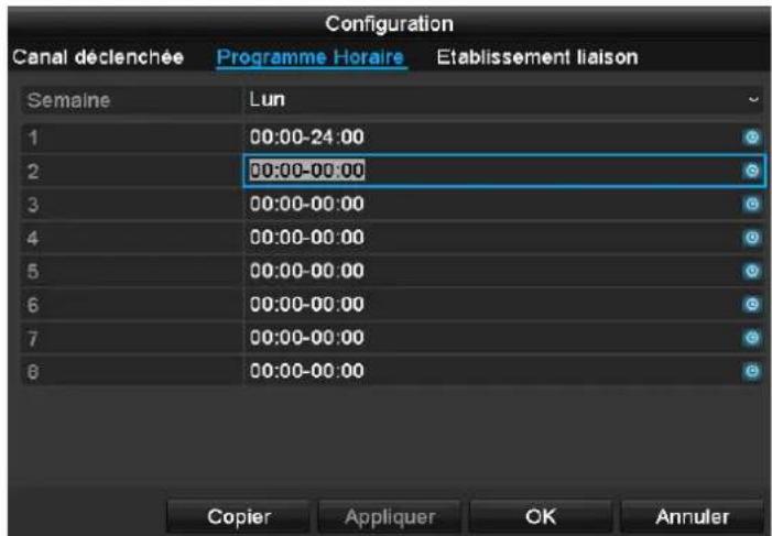
text_image
Configuration Canal déclenchée Programme Horaire Etablissement liaison Semaine Lun 1 00:00-24:00 2 00:00-00:00 3 00:00-00:00 4 00:00-00:00 5 00:00-00:00 6 00:00-00:00 7 00:00-00:00 8 00:00-00:00 Copier Appliquer OK Annulertext_image
Config Enrollment Calendar Coupon Coupon derivatives Coupon Coupon Series Coupon Coupon Coupon Coupon Coupon Coupon Coupon Coupon Coupon Coupon Coupon Coupon Coupon Coupon Coupon Coupon Coupon Coupon Coupon Coupon Coupon Coupon Coupon Coupon Coupon Coupon Coupon Coupon Coupon Coupon Coupon Coupon Coupon Coupon Coupon Coupon Coupon Coupon Coupon Coupon Coupon Coupon Coupon Coupon Coupon Coupon Coupon Coupon Coupon Coupon Currency Currency Currency Currency Currency Currency Currency Currency Currency Currency Currency Currency Currency Currency Currency Currency Currency Currency Currency Currency Currency Currency Currency Currency Currency Currency Currency Currency Currency Currency Currency Currency Currency Currency Currency Currency Currency Currency Currency Currency Currency Currency Currency Currency Currency Currency Currency Currency Currency Currency Currencytext_image
Sauvegarder Exportation 2/3: Annuleri
Remarque
'PPP over Ethernet' (protocole Point-to-Point)
'Universal Serial Bus'
natural_image
White rectangular electronic device with a blue internal line and '2.1.1.1.1' label on the top (no other text or symbols visible)TAB Substream....266
text_image
1 2 3 4 5 6 7 8 9 0 Q W E R T Y U I O P A S D F G H J K L Z X C V B N M a Space Enter ESCIPv4 Address: 192.168.0.50
IPv4 Subnet Mask: 255.255.255.0
IPv4 Default Gateway: 192.168.0.1
Preferred DNS Server: 192.168.0.1

Henvisning
natural_image
Exterior view of a modern white building with a red 'ABUS' logo on the facade, surrounded by greenery and trees (no signage text in focus)I topteksten findes menuerne
- Menu
- Playback og
• PTZ.
text_image
Normal Event Tag External Filetext_image
Korfering General Network Active DOCS 2 PS Type: Active DOCS Status of the bus: new after transfer bus Status of the bus: Status of the bus: Status of the bus: Status of the bus: Status of the bus: Status of the bus: Status of the bus: Status of the bus: Status of the bus: Status of the bus: Status of the bus: Status of the bus: Status of the bus: Status of the bus: Status of the bus: Status of the bus: Status of the bus: Status of the bus: Status of the bus: Status of the bus: Status of the bus:text_image
Nonconfiging General Network Active NTP Live View Advanced Begin Active NTP 80 @ IP address @ pin ID: 100 NTP name: 123 Live View Active Tbps
Henvisning
text_image
Configuring Close Default User View Advanced Target Active name: d018349 User Name: Password: SMTP server SMTP goal: Active SQL Password: Password: default Active retailer: Mortager 1 Maintenance: Maintenance: default Vehicle links: Invent: 2% Test Avend Estagetext_image
Koogering NodePath Network Line View Adversal Stage Project administrator path No. User Name Level MAC-advance No stage Ret Load Set 1 admin Access 60.00 60.00 69.00 2 GPTG Host 60.00 60.00 69.00 Line View Add Delete
Advarsel
Notér administratorkodeordet.
text_image
Optogative Options Options on which there is Options on which there is Options on which there is Options on which there is Options on which there is Options on which there is Options on which there is Options on which there is Options on which there is Options on which there is Options on which there is Options on which there is Options on which there is Options on which there is Options on which there is Options on which there is Options on which there is Options on that Options on that Options on that Options on that Options on that Options on that Options on that Options on that Options on that Options on that Options on that Options on that Options on that Options on that Options on that Options on that Options on that Options on that Options on that Options on that Options on that Options on that Options on that Options on that Options on that Options on the other side of this section. Options to include: Options to include: Options to include: Options to include: Options to include: Options to include: Options to include: Options to include: Options to include: Options to include: Options to include: Options to include: Options to include: Options to include: Options to include: Options to include: Options to include: Options to include: Options to include: Options to include: Options to include: Options to include: Options to include: Options to include: Options to include: Options to include: Options to include: Options to include: Options to include: Options to include: Options to include: Options to include: Options to include: Options to include: Options to include: Options to include: Options to include: Options to include: Options to include: Options to include: Options to include: Options to include: Options to include: Options to include: Options to include: Options to include: Line View Available Upgradetext_image
Options Tidoplan Kodning Udvedo tockill... Fare Farowschüllinger Nr Name Status Start-upset Start-upset Redesign 1 Heli day8 Deactive 1 JanMarketing 1.JanMarketing 2 Heli day2 Deactive 1 JanMarketing 1.JanMarketing 3 Heli day3 Deactive 1 JanMarketing 1.JanMarketing 4 Heli day4 Deactive 1 JanMarketing 1.JanMarketing 5 Heli day5 Deactive 1 JanMarketing 1.JanMarketing 6 Heli day6 Deactive 1 JanMarketing 1.JanMarketing 7 Heli day7 Deactive 1 JanMarketing 1.JanMarketing 8 Heli day8 Deactive 1 JanMarketing 1.JanMarketing 9 Heli day9 Deactive 1 JanMarketing 1.JanMarketing 10 Heli day10 Deactive 1 JanMarketing 1.JanMarketing 11 Heli day11 Deactive 1 JanMarketing 1.JanMarketing 12 Heli day12 Deactive 1 JanMarketing 1.JanMarketing Live visiting Tribagstext_image
Vorigipholator Systemo Protocountings Report Refugent Upgrade Standard Not Dated LANT Send 44 Bits Meeting 74 Bits Notes Linking Status Type MAC Analysis SET/OUT INC Type Truts LAN1 Kuwait Eached 50.0x7.48.26 x 0.3x 100% 100% Full-Up Energy Energytext_image
Verkaufholter Systems Protoklagerung Import Lockport Upgrade Standard Net Extract Trade: Registering of networks Network Data Type: Transfers Access Reversiting: 0fps Remote Advertising: 0fps Net Total video: 46Mbps Attachering Line View Tags: Tags:86444 Affing (Germany)
Grabador de vídeo de red de 4 canales ABUS TVVR36000

natural_image
White wireless router device with a blue stripe and logo (no visible text or symbols on body)text_image
1 2 3 4 5 6 7 8 9 0 Q W E R T Y U I O P A S D F G H J K L Z X C V B N M a Space Enter ESCnatural_image
Exterior view of a modern white building with a red logo on the roof, surrounded by greenery and trees (no visible text or symbols on the building itself)text_image
ConfigDev Struts Network Port DONG Email PHP Main queries Network 08 Network: 200 8 package.org Cable: PHP USB Location: Address to Directs Cancel Helpi
Nota
text_image
Event Name Event Events Topic Events Date/One Index Date/One File Time D1 D2 D3 D4 D5 D6 Vista Live Recise Help totext_image
Undercards Normal to default Comparities: Default Comparities: Actual data: All my. Pre-district End records Comparities: Default Comparities: Post Principal Change in value Post-Source Parameters Proprietor Subscripts End 12.00 Finish Next Call Helptext_image
Material Imported by: Transporter in the Configuration Activeories and Fees For details Not applicable Material Options Material Type Material Description Transfer to Transfer to Transfer to Transfer to Transfer to Transfer to Transfer to Transfer to Transfer to Transfer to Transfer to Transfer to Transfer to Transfer to Transfer to Transfer to Transfer to Transfer to Transfer to Transfer to Transfer to Transfer to Transfer to Transfer to Transfer to Transfer to Transfer to Transfer to Transfer to Transfer to Transfer to Transfer to Transfer to Transfer toi
Nota
86444 Affing (Germany)
natural_image
White wireless router device with ventilation grille and a blue stripe (no visible text or symbols)Instrukcja obsługi
Wersja 1.0
CE
Polski
TAB Substream....404
text_image
1 2 3 4 5 6 7 8 9 0 Q W E R T Y U I O P A S D F G H J K L Z X C V B N M a Space Enter ESCnatural_image
Exterior view of a modern white building with a red 'ABUS' logo on the facade, surrounded by greenery and trees (no readable text or symbols beyond branding)text_image
Kontiger Systems Open PFPOE TCP NTP E-mail UPNP Mail Grey Outlook Solutions Open PFPOE TCP NTP E-mail UPNP Mail Grey Outlook Open PFPOE TCP OK/OK/OK Open PFPOE TCP NTP E-mail UPNP Mail Grey Outlook Open PFPOE TCP OK/OK/OK Open PFPOE TCP NTP E-mail UPNP Mail Grey Outlook Open PFPOE TCP OK/OK/OK Open PFPOE TCP NTP E-mail UPNP Mail Grey Outlook Open PFPOE TCPtext_image
Target Options Options File Project File Path File Name File Type File Date File Address File Location File Address File Date File Name File Address File Date File Address File Date File Address File Date File Address File Date File Address File Date File Address File Date File Address File Date File Address File Date File Address File Date File Address File Date File Address File Date File Address File Date File Address File Date File Address File Date File Address File Date File Address File Date File Address File Date File Addresstext_image
Kündig System File Edit View Help File Name Format Edit Mode Tools Up Output From 1 admin AutoDrive 00:00:00:00:00 2 good User 00:00:00:00:00 Add Window
Ostrzeżenie
,Universal Serial Bus'
natural_image
White wireless router device with ventilation grille and a blue stripe (no visible text or symbols)Bruksanvisning
Version 1.0
CE
Svenska
text_image
1 2 3 4 5 6 7 8 9 0 Q W E R T Y U I O P A S D F G H J K L Z X C V B N M a Space Enter ESCnatural_image
Exterior view of a modern white building with a red 'ABUS' logo on the facade, surrounded by greenery and trees (no signage text in focus)text_image
KoRigierung General Network Network Intersecting Underleg Interactions Network IP address IP address IP address IP address IP address IP address IP address IP address IP address IP address IP address IP address IP address IP address IP address IP address IP address IP address IP address IP address IP address IP address IP address IP address IP address IP address IP address IP address IP address IP address IP address IP address IP address IP address