
IPCA54512B - Surveillance Camera ABUS - Free user manual and instructions
Find the device manual for free IPCA54512B ABUS in PDF.

| Product type | Surveillance camera |
| Brand | ABUS |
| Model | IPCA54512B |
| Category | Surveillance camera |
| Housing shape | Dome |
| Housing color | White |
| Resolution | 4 MPx (2688x1520) |
| Lens | Fixed focal length 4.0 mm |
| Built-in microphone | Yes |
| Alarm input/output | No |
| Protection rating | IP66 (indoor and outdoor) |
| Power supply | PoE (Power over Ethernet) or power adapter (12 V DC) |
| Power consumption | Approx. 6 W |
| Operating temperature | -30 °C to +50 °C |
| Night vision | IR LED, range up to 30 m |
| Video codec | H.265, H.264, MJPEG |
| Local storage | microSD card (max. 256 GB) |
| Connectivity | Ethernet 10/100/1000 Base-T |
| Intelligent object detection | People and vehicles |
| Security functions | Digest authentication, IP/MAC filter, HTTPS, certificate, lockout after failures |
| Maintenance and cleaning | Cleaning with a dry or slightly damp cloth (no chemicals) |
| Repairability | No user-serviceable parts – entrust to a professional |
Frequently Asked Questions - IPCA54512B ABUS
User questions about IPCA54512B ABUS
0 question about this device. Answer the ones you know or ask your own.
Ask a new question about this device
Download the instructions for your Surveillance Camera in PDF format for free! Find your manual IPCA54512B - ABUS and take your electronic device back in hand. On this page are published all the documents necessary for the use of your device. IPCA54512B by ABUS.
USER MANUAL IPCA54512B ABUS
natural_image
Three white surveillance cameras with digital displays, no visible text or symbolsD Bedienungsanleitung Software
UK User manual software
FR Manuel utilisateur logiciel
NL Gebruikershandleiding software
DK Brugerhåndbog software
① Manuale operativo
| D | Diese Bedienungsanleitung enthält wichtige Hinweise zur Inbetriebnahme und Handhabung.Achten Sie hierauf, auch wenn Sie dieses Produkt an Dritte weitergeben.Heben Sie deshalb diese Bedienungsanleitung zum Nachlesen auf!Eine Auflistung der Inhalte finden Sie im Inhaltsverzeichnis mit Angabe der entsprechenden Seitenzahlen auf Seite 8. | DK | Denne manual hører sammen med dette produkt. Den indeholder vigtig information som skal bruges under opsætning og efterfølgende ved service. Dette skal huskes også når produkter gives videre til anden part. Læs derfor denne manual grundigt igennem også for fremtiden.Indholdet kan ses med sideanvisninger kan findes i indekset på side 297. |
| GB | These user manual contains important information for installation and operation. This should be also noted when this product is passed on to a third party. Therefore look after these operating instructions for future reference!A list of contents with the corresponding page number can be found in the index on page 79. | I | Queste istruzioni per l'uso contengono importanti informazioni sulla messa in servizio e la gestione. Prestare attenzione a questo, anche se si cede questo prodotto a terzi. Conservare quindi queste istruzioni per l'uso per consultazioni future!Un elenco dei contenuti è disponibile nell'indice con i numeri di pagina corrispondenti a pagina 369. |
| F | Ce mode d'emploi appartient à de produit. Il contient des recommandations en ce qui concerne sa mise en service et sa manutention. Veuillez en tenir compte et ceci également lorsque vous remettez le produit à des tiers. Conservez ce mode d'emploi afin de pouvoir vous documenter en temps utile!Vous trouverez le récapitulatif des indications du contenu á la table des matières avec mention de la page correspondante á la page 151. | ||
| NL | Deze gebruiksaanwijzing hoort bij dit product. Er staan belagrijke aanwijzingen in betreffende de ingebruikname en gebruik, ook als u dit product doorgeeft aan derden. Bewaar deze handleiding zorgvuldig, zodat u deze later nog eens kunt nalezen!U vindt een opsomming van de inhoud in de inhoudsopgave met aanduiding van de paginanummers op pagina 224. | ||
IPCA34\*\*\* / IPCA54\*\*\* / IPCA64\*\*\*
natural_image
Three white surveillance cameras with digital displays, shown from different angles (no text or symbols visible)Bedienungsanleitung
Version 09/2024
CE
100M Full-dup; 10M/100M/1000M Auto
DHCP
Trap-Community: TRAP-Community String
SNMP v3
8.4 Video & Audio
8.4.1 Video Stream Einstellungen

Links: hohe Empfindlichkeit.
Zeitplan
natural_image
Three white surveillance cameras with digital displays, shown from different angles (no visible text or symbols)Operating instructions
Version 09/2024
CE
English translation of the original operating instructions in German. Retain for future reference.
Introduction
Dear customer,
Thank you for purchasing this product.
The device complies with the requirements of the following EU directives: EMC Directive 2014/30/EU and the RoHS Directive 2011/65/EU.
To ensure this remains the case and to guarantee safe operation, it is your obligation to observe these operating instructions!
Please read the entire user guide carefully before commissioning the product and pay attention to all operating instructions and safety information.
All company names and product descriptions are trademarks of the corresponding owner. All rights reserved.
If you have any questions, please contact your specialist installation contractor or specialist dealer!

Disclaimer
This user guide has been produced with the greatest of care. Should you discover any omissions or inaccuracies however, please inform us in writing at the address provided on the back of the manual. ABUS Security-Center GmbH & Co. KG does not accept any liability for technical and typographical errors, and reserves the right to make changes to the product and user guides at any time and without prior warning. ABUS Security-Center GmbH is not liable or responsible for direct or indirect damage resulting from the equipment, performance and use of this product. No guarantee is made for the contents of this document.
Explanation of symbols
 | The triangular high voltage symbol is used to warn of the risk of injury or health hazards (e.g. caused by electric shock). |
 | The triangular warning symbol indicates important notes in this user guide which must be observed. |
 | This symbol indicates special tips and notes on the operation of the unit. |
Important safety information
 | All guarantee claims are invalid in the event of damage caused by non-compliance with this user guide. We cannot be held liable for resulting damage. |
 | We cannot be held liable for material or personal damage caused by improper operation or non-compliance with the safety information. All guarantee claims are void in such cases. |
The following safety information and hazard notes are not only intended to protect your health, but also to protect the device from damage. Please read the following points carefully:
- There are no components inside the product that require servicing. Dismantling the product invalidates the CE certification and the guarantee/warranty.
- The product may be damaged if it is dropped, even from a low height.
• Install the device so that the image sensor is not subjected to direct sunlight. Pay attention to the installation instructions in the corresponding section of this user manual. - The device is designed for indoor and outdoor use (IP66).
Avoid the following adverse conditions during operation:
- Moisture or excess humidity
• Extreme heat or cold - Direct sunlight
- Dust or flammable gases, vapours or solvents
• Strong vibrations
• Strong magnetic fields (e.g. next to machines or loudspeakers) - The camera must not be installed on unstable surfaces.
General safety information:
- Do not leave packaging material lying around. Plastic bags, sheeting, polystyrene packaging, etc. can pose a danger to children if played with.
- The video surveillance camera contains small parts which could be swallowed and must be kept out of the reach of children for safety reasons.
- Do not insert any objects into the device through the openings.
- Only use replacement devices and accessories that are approved by the manufacturer. Do not connect any non-compatible products.
• Please pay attention to the safety information and user manuals for the other connected devices. - Check the device for damage before putting it into operation. Do not put the device into operation if you identify any damage.
- Adhere to the normal voltage limits specified in the technical data. Higher voltages could destroy the device and pose a health risk (electric shock).
Safety information
- Power supply: Note the information provided on the type plate for supply voltage and power consumption.
- Overloading
Avoid overloading electrical sockets, extension cables and adapters, as this can result in fire or electric shock.
- Cleaning
Only use a damp cloth to clean the device. Do not use corrosive cleaning materials.
Disconnect the device from the power supply before cleaning.
Warnings
Observe all safety and operating instructions before putting the device into operation for the first time.
-
Observe the following information to avoid damage to the power cable and plug:
-
Do not pull the cable when disconnecting the device from the power – always take hold of the plug.
-
Ensure that the power cable is positioned as far away as possible from any heating equipment, as this could otherwise melt the plastic coating.
-
Follow these instructions. Non-compliance with these instructions could lead to electric shock:
-
Never open the housing or power supply unit.
-
Do not insert any metallic or flammable objects into the device.
• Use surge protection to prevent damage caused by overvoltage (e.g. in electrical storms). -
Disconnect defective devices from the power immediately and contact your specialist dealer.
 | When installing the device in an existing video surveillance system, ensure that all devices have been disconnected from the mains power circuit and low-voltage circuit. |
 | If in doubt, have a specialist technician carry out assembly, installation and connection of the device. Improper or unprofessional work on the mains network or domestic installations puts both you and others at risk.Connect the installations so that the mains power circuit and low-voltage circuit always run separately from each other. They should not be connected at any point or become connected as a result of a malfunction. |
Unpacking the device
Handle the device with extreme care when unpacking it.
| If the original packaging has been damaged, inspect the device. If the device shows signs of damage, return it in the original packaging and inform the delivery service. |
Contents
- Intended use....82
- Explanation of symbols 82
- Features and functions 83
- Device description....83
- Description of the connections 83
- Initial start-up 84
6.1 Using the ABUS IP Installer for camera search 84
6.2 Accessing the network camera via a web browser 85
6.3. General instructions for using the settings pages 85
6.4 Installing video plugin....85
6.5 Initial password assignment....86
6.6 Home page (login page)....87
6.7 User accounts and passwords....88
6.8 Connecting the camera to ABUS NVR....88
6.9 Connecting the camera to ABUS Link Station app 88
6.10 Connecting the camera to ABUS CMS 89
6.11 Notes for installation when using object detection 89
- User functions....90
7.1 Menu bar....90
7.2 Live image display....91
7.3 Control bar 91
7.4 Playback....92
7.5 Image 93
- Configuration 95
8.1 Local configuration....95
8.2 System 97
8.2.1 System settings....97
8.2.1.1 Basic information....97
8.2.1.2 Time settings....98
8.2.1.3 DST / Summer Time 99
8.2.1.4 RS-232....99
8.2.1.5 VCA Resource 100
8.2.1.6 Meta Data Settings....100
8.2.1.7 About / Licence information....100
8.2.2 Maintenance....101
8.2.2.1 Upgrade and maintenance....101
8.2.2.2 Protocol....102
8.2.2.3 Security Audit Protocol....102
8.2.3 Security 102
8.2.3.1 Authentication 102
8.2.3.2 IP address filter 103
8.2.3.3 MAC address filter....103
8.2.3.4 Security service....104
8.2.3.5 Enhanced security....104
8.2.3.6 Certificate Management....104
8.2.4 Managing users....105
8.2.4.1 Online users....105
8.2.4.2 Account security settings 106
8.3 Network 107
8.3.1 TCP/IP....107
8.3.2 DDNS....108
8.3.3 Port....109
8.3.4 NAT 110
8.3.5 Multicast....111
8.3.6 SNMP....111
8.3.7 FTP 112
8.3.8 Email 113
8.3.9 Cloud access / ABUS Link Station 114
8.3.10 HTTPS 115
8.3.11 QoS....115
8.3.12 802.1X....116
8.3.13 Integration protocol 116
8.3.14 Network service....116
8.3.15 Alarm server....116
8.3.16 SRTP....117
8.4 Video & Audio 118
8.4.1 Video stream settings....118
8.4.2 Audio....119
8.4.3 ROI (Region of Interest)....119
8.4.4 Stream information....119
8.5 Image 120
8.5.1 Display settings....120
8.5.2 OSD settings....124
8.5.3 Privacy mask....125
8.5.4 Image parameter change....125
8.6 Events....126
8.6.1 Motion detection....126
8.6.2 Cover Detection 128
8.6.3 Alarm input (IPCA54572A)....129
8.6.4 Alarm output (IPCA54572A)....131
8.6.5 Exceptions....132
8.6.6 Flashing Alarm Light Output (IPCA54572A) 132
8.6.7 Audible alarm output (IPCA54572A) 133
8.6.8 Intrusion detection....134
8.6.9 Tripwire 136
8.6.10 Area input detection 138
8.6.11 Area output detection....140
8.7 Storage 142
8.7.1 Record schedule 142
8.7.2 Capture / Single frame 143
8.7.3 Storage Management....144
8.7.4 NAS....144
9. Maintenance and cleaning 145
9.1 Maintenance....145
9.2 Cleaning....145
10. Disposal....145
11. Technical data....146
12. Open Source Licence information 146
1. Intended use
This camera is used for indoor and outdoor video surveillance (depending on the model) in conjunction with a recording device or appropriate display unit (e.g. PC).

Use of this product for any other purpose than that described above may lead to damage to the product and other hazards. All other uses are not as intended and will result in the invalidation of the product guarantee and warranty. No liability can be accepted as a result. This also applies to any alterations or modifications made to the product. Read the operating instructions fully and carefully before using the product. The operating instructions contain important information on installation and operation.
2. Explanation of symbols
 | The triangular high voltage symbol is used to warn of the risk of injury or health hazards, e.g. caused by electric shock. |
 | The triangular warning symbol indicates important notes in this user guide which must be observed. |
 | This symbol indicates special tips and notes on the operation of the unit. |
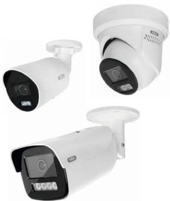
3. Features and functions

The effective IR range will depend on the installation location. If there are surfaces that absorb light or no objects that reflect IR light in the field of view, the IR range will be reduced and/or the video image will be too dark. Furthermore, reflective objects in the immediate vicinity of the camera (e.g. roof gutter or wall) may also result in the reflection of IR light, which can disrupt the image.
| Item number. | Housing | Housing color | Resolution | Lens | Alarm input / Mic output | |
| IPCA34512A | Mini Tube | weiß 4 MPx | 2.8 mm | - | ||
| IPCA34512B | Mini Tube | weiß 4 MPx | 4.0 mm | - | ||
| IPCA34612A | Mini Tube | schwarz 4 MPx | 2.8 mm | - | ||
| IPCA54512A | Dome weiß | 4 MPx 2.8 mm | - | |||
| IPCA54512B | Dome weiß | 4 MPx 4.0 mm | - | |||
| IPCA54612A | Dome schwarz | 4 MPx 2.8 mm | - | |||
| IPCA64512A | Tube weiß | 4 MPx 2.8 mm - | - | |||
| IPCA64512B | Tube weiß | 4 MPx 4.0 mm - | - | |||
| IPCA64612A | Tube | schwarz 4 MPx | 2.8 mm - - | |||
| IPCB54572A | Dome | weiß | 4 MPx | 2.8 mm |
4. Device description
For more information on connections and the correct installation of the IP camera, please refer to the installation instructions at www.abus.com.
5. Description of the connections
For more information on connections and the correct installation of the IP camera, please refer to the installation instructions at www.abus.com.
6. Initial start-up
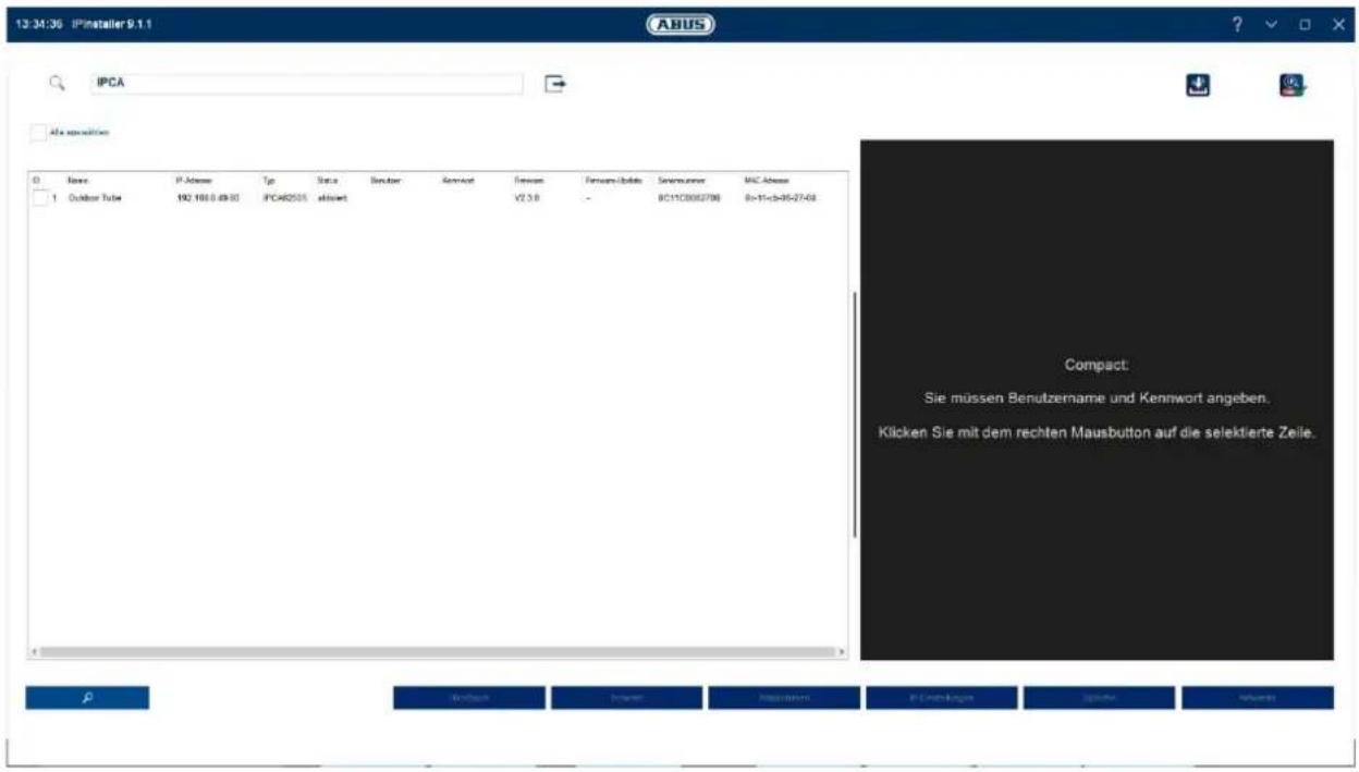
6.1 Using the ABUS IP Installer for camera search
Install and start the ABUS IP Installer. This is available for each respective product from the ABUS website www.abus.com.
The IP camera should now appear in the selection list without the relevant IP address for the target network, where appropriate. The IP settings for the camera can be changed using the IP installer.
Using the "Browser" button, a previously selected camera can be opened directly in the internet browser (the default browser for Windows will be used).
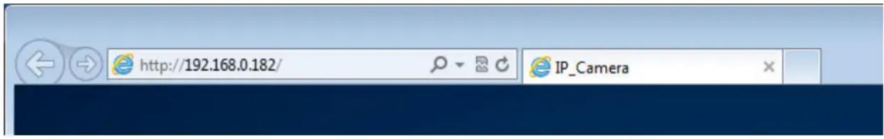
6.2 Accessing the network camera via a web browser
Enter the camera's IP address into the browser's address bar (if a different HTTP port is used in Internet Explorer you must also enter "http://" before the IP address.)
6.3. General instructions for using the settings pages
| Functional element | Description |
 | Save settings that have been made on the page.Please note that the new settings will only apply after the save button has been pressed. |
 | Function activated |
 | Function deactivated |
 | List selection |
 | Input field |
 | Slide control |
6.4 Installing video plugin
Internet Explorer
A plugin called ActiveX is used for displaying videos in Internet Explorer. This plugin must be installed in the browser. You will be asked to confirm the installation directly after entering your user name and password.
 | If the ActiveX Plugin installation is blocked by Internet Explorer, you will need to reduce your security settings to install/initialise ActiveX. |
Mozilla Firefox/Google Chrome/Microsoft Edge
A further video plugin is required for displaying videos in these browsers. In the area to the upper right of the live view, this plugin is offered for download and installation on the PC.
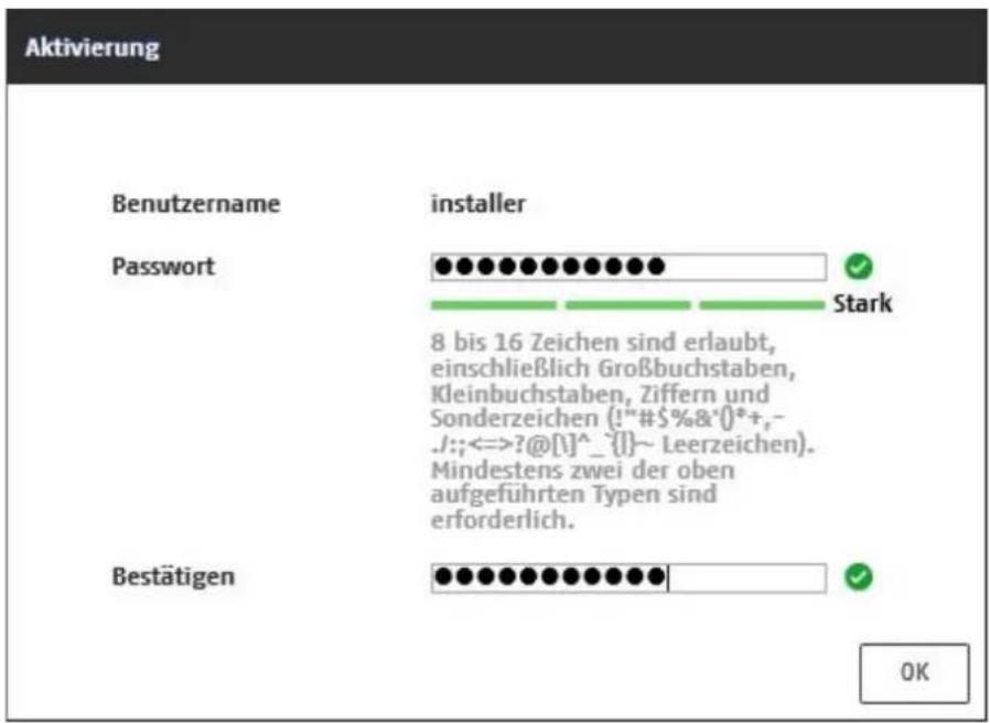
6.5 Initial password assignment
For IT security reasons, use of a secure password with the appropriate usage of lower-case letters, capital letters, numbers and special characters is recommended.
Passwords are not factory set and must be assigned when the camera is used for the first time. This can be done via the ABUS IP installer ('Enable' button), or via the website.
A secure password must meet the following minimum requirements:
- 8–16 characters
- Valid characters: Numbers, lower-case letters, capital letters, special characters (!"#\$%&()*+,-./;;<=>?@[]^_{|}\~space)
- You must use at least two different types of character
After setting the initial password, you should immediately add an email address to your account security settings.
You can use this email address to receive a password reset code if you forget your administrator password. To do this, you must use the QR code scan function in the Link Station app (you do not need to have a Link Station account).
For more information, see the "Account security settings" section (section 8.2.4.2).
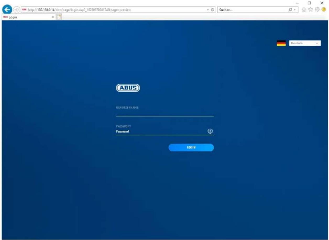
6.6 Home page (login page)
After entering the IP address in the browser's address bar and opening up the page, the home page will appear.
6.7 User accounts and passwords
Overview of the types of user with the user name descriptions, the default passwords and the corresponding privileges:
| User type User name Default password Privileges | |||
| Administrator(for access via web browser, mobile app or recording device) | installer | Full access | |
| Operator | andassigned and modified by admin> | Can be activated individually:Live viewPlayback SD/NASSingle frame search SD/NAS(PT)Z ControlManual recordingRestartTwo-way AudioFormatting the SD cardChanging parameters in settings | |
| User(for access via web browser) | Live viewPlayback SD/NASSingle frame search SD/NAS | ||
6.8 Connecting the camera to ABUS NVR
The following information is required to connect the camera to ABUS NVR:
• IP address/domain name
• Server Port (Standard 8000)
- User name: installer
- Password:
6.9 Connecting the camera to ABUS Link Station app
About P2P Cloud function:
• QR code or 9-digit part of the software serial number
( example: IPCS6213020210121AAWRF12345678 )
- Assigned password for the P2P Cloud function
Alternative:
The following information is required to connect the camera via the IP address:
• IP address/domain name
• Server Port (Standard 8000)
- User name: installer
- Password:
6.10 Connecting the camera to ABUS CMS
The following information is required to connect the camera to ABUS CMS software:
• IP address/domain name
- http port (default 80)
- rtsp port (default 554)
- User name: installer
- Password:
6.11 Notes for installation when using object detection
The camera's object detection can detect people and vehicles as objects. Other disturbances are thus ignored.
For the object detection to perform optimally, certain frame conditions must be observed during installation or with the camera's field of view.
- The installation height of the camera should be selected between 2.5 and 5 metres. The inclination should not exceed 10 degrees.
- The object height in the selected image section must be between 1/16 and 1/2 of the image height. If objects in the image are shown too large or too small, they may not be detected correctly.
- Note that below the camera a certain area is not under surveillance.
- The maximum surveillance distance depending on the focal length of the camera is as follows:
| Focal length | Max. surveillance distance |
| 2.8 mm 10 m | |
| 4 mm 15 m | |
| 6 mm 22 m | |
| 8 mm 30 m | |
| 12 mm 40 m |
- Reflective surfaces in the image section can confuse object detection.
- Make sure that there are no branches or leaves in close proximity to the camera in the image section.
- Dome cameras are less suitable for outdoor surveillance with object detection, as light scatter or light reflection can occur in the dome. This affects the object detection.
- Do not use object detection in areas with a correspondingly high number or frequency of lenses (people, vehicles). This results in a high number of alarms.
- Please note that human or vehicle-like structures (e.g. images of people) could also trigger the alarm detector in the camera (e.g. an abandoned advertising banner with people on it).
7. User functions
Open the network camera home page. The interface is divided into the following main areas:
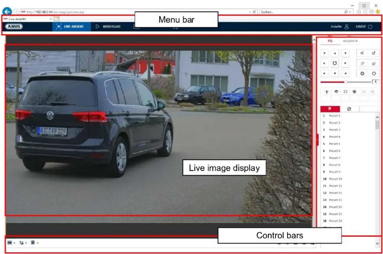
7.1 Menu bar
Make a selection by clicking on the appropriate tab: "Live View", "Playback", "Image" or "Configuration".
| Button Description | ||
| installer | ||
| LOGOUT | ||
| Live view Live image display | ||
| Playback Playback of video data on the microSD card | ||
| Image | Image retrieval of stored individual images (e.g. captured number plates) | |
| Configuration Configuration pages of the IP camera | ||
7.2 Live image display
You can switch to the full-screen view by double-clicking. At the bottom left of the control bar is a button for adjusting the display format.
| Button Description | |
 | Activate 4:3 view |
 | Activate 16:9 view |
 | Display original size |
 | Automatically adjust view to browser |
7.3 Control bar
| Button Description | |
 | Video stream selection |
 | Video plugin selection (installed ABUS_IPC_Web_Plugin or Quicktime Video Plugin) |
 | Activating the microphone on the PC for two-way audio communication |
 | Pixel counter (function to determine the minimum horizontal number of pixels of a number plate) |
| [SHRC] | Start / stop live display |
| [WRK] | Instant image (snapshot) on PC |
| [OKCK] | Start / stop manual recording on PC |
| [SHRK] | Digital zoom |
| [KBW7] | Activating the loudspeaker on the PC, incl. volume setting |
 | Lens: Zoom - / Zoom + (if available) |
 | Lens: Focus - / Focus + (if available) |
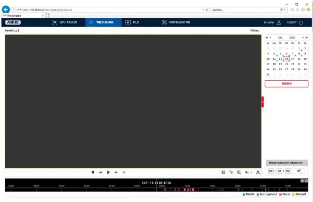
7.4 Playback
In this menu, recordings can be searched for on the corresponding data storage device or drive and downloaded to the PC (e.g. SD card).
| Button Description | |
| Stop playback | |
| Slow Forward | |
| Pause | |
| Fast Forward | |
| Frame forwards | |
| Save single frame to PC | |
| Video clip function | |
| Digital zoom (also during playback) | |
| Activating the loudspeaker on the PC, incl. volume setting | |
Downloading recorded video files | |
 | Calendar with day selection. A blue triangle indicates that recordings exist for a particular day. |
| DurchgehendAlarm | Marking of the recording type (continuous recording, event recording) |

It may be necessary to start the browser with so-called admin rights in order to successfully save files on the PC.
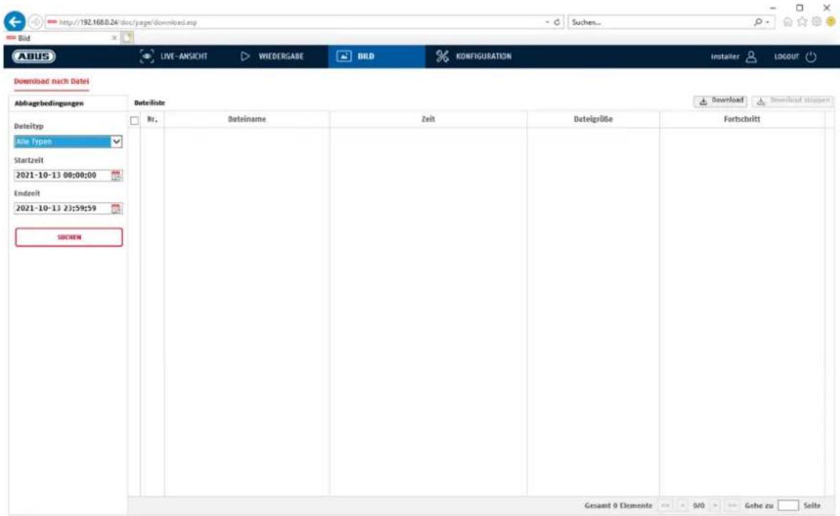
7.5 Image
In this menu, single frames can be downloaded from the corresponding data storage device or drive and downloaded to the PC (e.g. SD card).
File type: Select the event type that caused the single frame to be saved and that you want to search for
Start time / End time: Date and time constraints
Search: Start search
Download: First select the files you want to download.
Press this button to start the download.
| It may be necessary to start the browser with so-called admin rights in order to successfully save files on the PC. |
8.1 Local configuration
Under the "Local configuration" menu item, you can select settings for the live view, file paths of the recordings and snapshots.
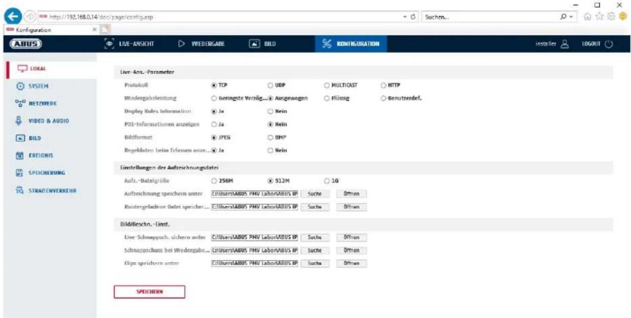
Here you can set the protocol type and the live view performance of the camera.
Protocol
TCP: Transmission Control Protocol: Transmission protocol with safeguarding against transmission errors. If there is a transmission error, packages are resent. However, if the error frequency is too high, this protocol is negative for real-time transmission.
UDP: Real-time audio and video transmission without security mechanism
MULTICAST: Use of the multicast protocol (the network components must support multicast). Additional multicast settings can be found under Configuration/Network.
HTTP: Control and video data are tunnelled via the HTTP port.
Live view performance
You can set the performance level for the live view here.
Live Indicator (Rules Information)
As soon as this function has been enabled, a frame will be displayed around the triggered area in the live image for used and triggered motion detection.
Image format
Setting of the format in which the single frame from the live view (Instant image button) should be saved (JPEG, BMP).
Record file settings
You can define the file size for recordings, the recording path and the path for downloaded files here. To apply the changes, click "Save".
Recording file size
You can choose between 256 MB, 512 MB and 1 GB as the file size for recordings and downloaded videos.
Save recordings to
You can determine the file path that is to be used for manual recordings here.
The default path used is C:\
Save downloaded files to
You can store the file path for downloaded videos here.
The following path is set by default: C:\
Image save settings
Here you can store the path for snapshots taken during playback as well as for video clips.
Save snapshots in live view to
Select the file path for instant images from the live view.
The following path is set by default: C:\
Save snapshots during playback to
You can store the path here for saving snapshots taken during playback.
The following path is set by default: C:\
Save clips to
You can specify the save path for storing edited video clips here.
The following path is set by default: C:\
8.2 System
8.2.1 System settings
8.2.1.1 Basic information
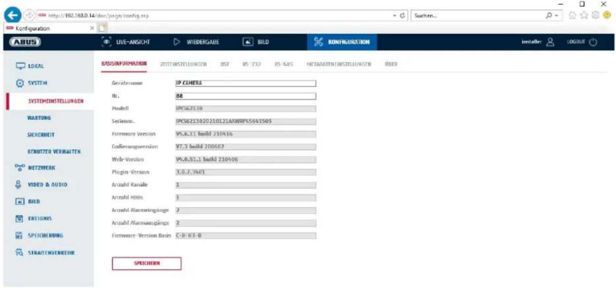
You can specify a device name for the camera here. Click on "Save" to apply the change.
Model:
Model number display
Serial No.:
Serial No. display
Firmware version:
Firmware version display
Encoding version:
Encoding version display
Number of Channels:
Display of the number of channels
Number of HDDs/SDs:
Number of installed storage media (SD card, max. one)
Number of Alarm Input:
Display of the number of alarm inputs
Number of Alarm Output:
Display of the number of alarm outputs
8.2.1.2 Time settings

Time zone selection (GMT).
Time setting methods
NTP
Using the Network Time Protocol (NTP), it is possible to synchronise the time of the camera with a time server. Activate NTP to use the function.
Server Address
IP server address of the NTP server.
NTP Port
Network port number of the NTP service (default: port 123)
NTP update interval
1–10080 min.
Manual Time Sync.
Device time
Computer device time display.
Set time
Display of the current time using the time zone setting.
Click on "Sync. with computer time" to adopt the computer's device time.

Apply the settings by clicking "Save".
8.2.1.3 DST / Summer Time
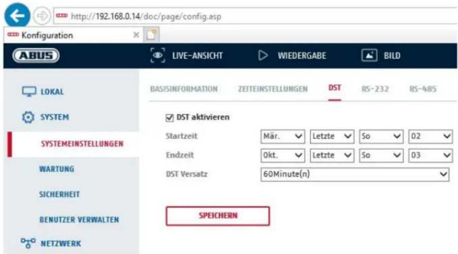
Activate the "Enable DST" checkbox to adjust the system time automatically to daylight saving time.
Start time
Specify the time for switching to daylight saving time.
End time
Specify the time for switching to standard time.
| Apply the settings by clicking “Save”. |
8.2.1.4 RS-232
The RS-232 interface for service purposes.
8.2.1.5 VCA Resource
The IP camera can be operated in 2 different modes. This setting has a direct influence on certain features or menu displays in the browser.
Smart Event Mode (Default):
In this mode, only 2 video streams are available (1st and 2nd video stream). This is sufficient for most applications. In particular, VCA functions with object detection (human, vehicle) are available (e.g. tripwire or intrusion detection).
Surveillance mode: In this mode, 3 video streams are available. VCA functions (Video
Content Analysis) such as Tripwire or Intrusion Detection are not available for selection. All DSP resources are used to generate the video streams.
8.2.1.6 Meta Data Settings
Metadata is raw data from VCA events (intrusion detection, tripwire, area entry, area exit).
Smart event: Activation of the collection of metadata for VCA events
Overlay rule image and target image on background image: The frames of the detection rule and the live detected object are displayed on the event image when saved.
Activate stream rule: Possibility of overlaying the rule frames in the sub-stream of the video stream.
8.2.1.7 About / Licence information
Display of license information
8.2.2 Maintenance
8.2.2.1 Upgrade and maintenance
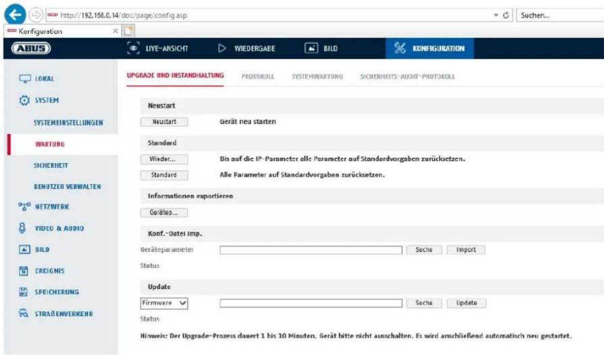
Click "Reboot" to reboot the device.
Standard
Restore
Click on "Restore" to reset all the parameters, except the IP parameters and user information, to the default settings.
Standard
Select this item to restore all parameters to default settings.
Import Config. File
Config File
Select a file path to import a configuration file here.
Status
Display of the import status.
Export Config. File
Click "Export" to export a configuration file.
Remote Upgrade
Firmware
Select the path to upgrade the camera with new firmware.
Status
Display of the upgrade status.
Automatic restart

Apply the settings by clicking "Save".
8.2.2.2 Protocol
The camera's log information can be displayed here. An SD card must be installed in the camera in order to save log information.
8.2.2.3 Security Audit Protocol
This protocol shows more details about the accesses of clients to the camera. This list can be exported as an Excel file.
Alternatively, the log information can be sent directly to a TCP server (log server) (e.g. using the software "Hercules SETUP utility" from "HW-group.com").
Furthermore, it is possible to create a self-signed certificate or upload a CA certificate on this menu page.
8.2.3 Security
8.2.3.1 Authentication
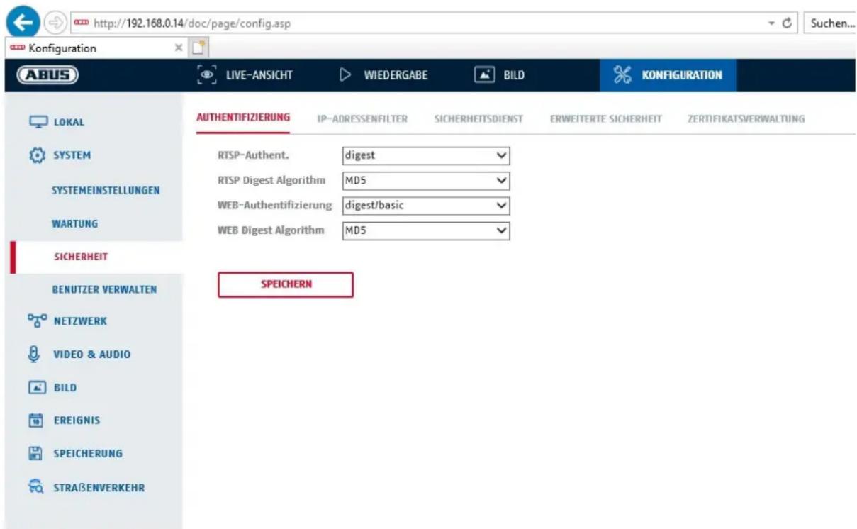
In this menu item, settings for security or encryption of access to the website for the camera as well as the retrieval of the video stream via the RTSP protocol can be made.
RTSP authentication:
The authentication mechanisms "digest" and "basic" are supported. The
"digest" setting is recommended if the client supports it.
RTSP Digest algorithm: MD5 – cryptographic hash function
SHA256 - security-enhanced cryptographic hash function
WEB authentication:
The authentication mechanisms "digest" and "basic" are supported. The "digest/basic" setting offers greater compatibility with different clients.
WEB Digest authentication:
cryptographic hash function
SHA256 - security-enhanced cryptographic hash function

Apply the settings by clicking "Save".
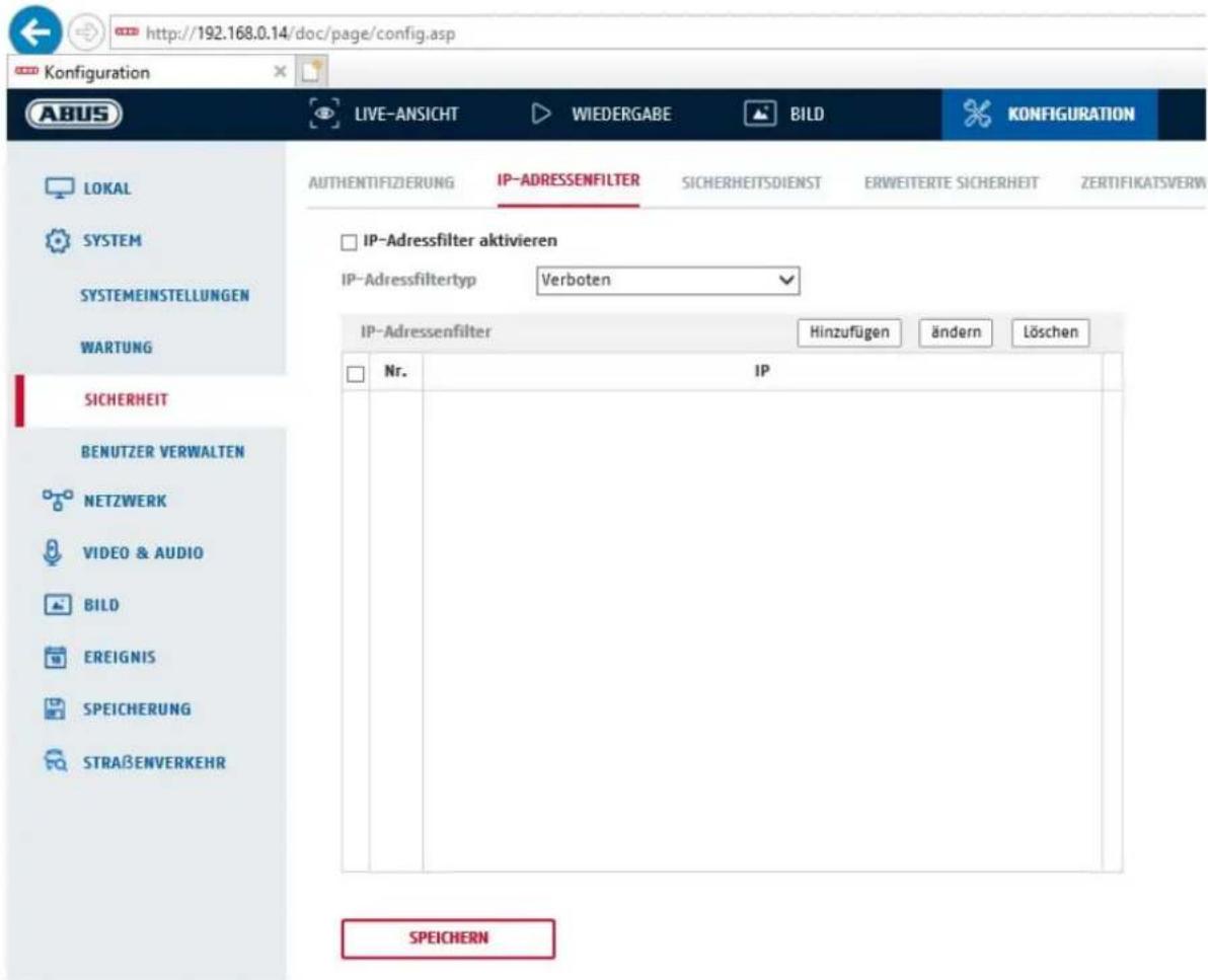
8.2.3.2 IP address filter
Enable IP address filter
Ticking the selection box enables the filter function.
IP Address Filter Type
Allowed: The IP addresses detailed further below can be used to access the camera.
Forbidden: The IP addresses detailed further below are blocked. An IP is entered in the format xxx.xxx.xxx.xxx.
8.2.3.3 MAC address filter
The functionality is analogous to the IP address filter, but applied to MAC addresses.
8.2.3.4 Security service
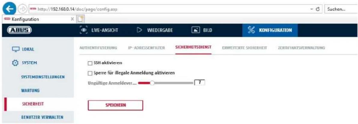
Enable illegal login lock
If this function is activated, camera access via the web interface is blocked if the user name or password are entered incorrectly (3 times... 20 times).
8.2.3.5 Enhanced security
Activate control timeout: If there is no active operation of the camera via the web
interface for a certain time (1 - 60 min., default 15 min.), the user is logged out.
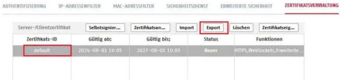
8.2.3.6 Certificate Management
In this menu, the following certificates and keys can be uploaded to the camera in order to then use them in the desired network function (e.g. 802.1X).
- Self-signed server and client certificates
- Server and client certificates (certificate and key or PKCS#12 package)
- Creation of a self-signed certificate
- CA certificate
There is also a function available for alerting when a certificate expires. In this case, an alert can be sent up to 1 - 30 days before the certificate expires. The alert action can be selected between sending an email and information via the ABUS CMS software (this must be permanently connected to the camera and active).
8.2.4 Managing users
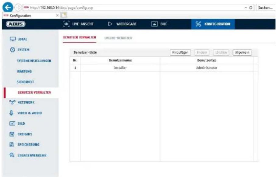
With this menu item, you can add, edit or delete users.
To add or modify a user, click "Add" or "Modify".
A new window with the data and authorisations appears.
User name
Here you assign the user name that needs to be entered for access to the camera.
User type
Select an individual user type for the user ID.
You can choose between two predefined levels: "Operator" or "User".
As a user, the following remote functions are available to you: playback, browse/query operating status.
To add further functions, select the corresponding checkbox.
Password
Here you assign the password that the corresponding user must enter to access the camera.
Confirm
Confirm the password by entering it again.

Apply the settings by clicking "OK".
Click "Cancel" to discard the data.
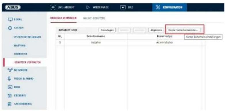
8.2.4.1 Online users
Display of the currently logged on users with IP address and time of activity.
8.2.4.2 Account security settings
After setting the initial password, you should immediately add an email address to your account security settings.
You can use this email address to receive a password reset code if you forget your administrator password. To do this, you must use the QR code scan function in the Link Station app (you do not need to have a Link Station account).
To be able to operate the camera via a network, the TCP/IP settings must be configured correctly.
NIC settings
NIC Type
Select the setting for your network adapter.
You can choose from the following values: 10M Half-dup; 10M Full-dup; 100M Half-dup; 100M Full-dup; 10M/100M/1000M Auto.
DHCP
If a DHCP server is available, click DHCP to apply an IP address and other network settings automatically. The data is transferred automatically from the server and cannot be changed manually.
If no DHCP server is available, please enter the following data manually.
IPv4 address
Setting of the IP address for the camera
IPv4 Subnet Mask
Manual setting of the subnet mask for the camera
IPv4 Default Gateway
Setting the default router for the camera.
IPv6 Mode
Manual: Manual configuration of IPv6 data.
DHCP: The IPv6 connection data is provided by the DHCP server.
Route Advertisement: The IPv6 connection data is provided by the DHCP server (router) in connection with the ISP (Internet Service Provider).
IPv6 Address
Display of the IPv6 address. The address can be configured in the IPv6 "manual" mode.
IPv6 Subnet mask
Display of the IPv6 subnet mask.
IPv6 Standard gateway
Display of the IPv6 default gateway (default router).
MAC address
The IPv4 hardware address of the camera is displayed here. This cannot be changed.
MTU
Setting of the transmission unit. Select a value between 500 and 9676. 1500 is set by default.
DNS Server
Preferred DNS server
DNS server settings are required for some applications (for example, sending emails). Enter the address of the preferred DNS server here.
Alternative DNS Server
If the preferred DNS server cannot be reached, this alternative DNS server is used. Please store the address of the alternative DNS server here.
Domain name settings
A dynamic domain name can be configured in this menu item. The camera can then be addressed in the local network using this name.
8.3.2 DDNS
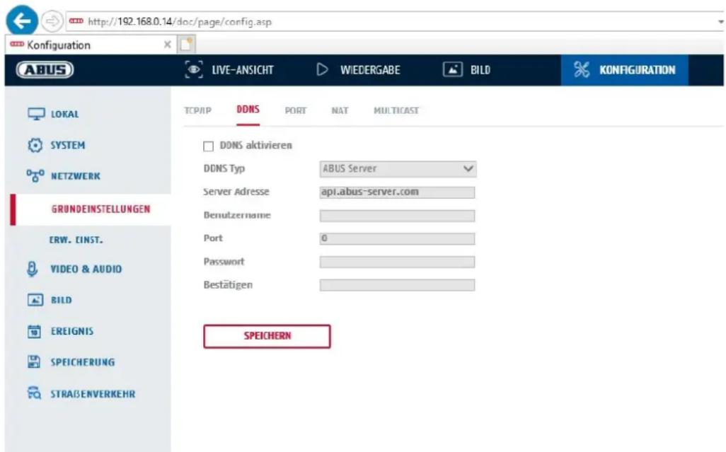
DDNS type: Select a service provider for the DDNS service (default: ABUS server)
Server Address:
IP address of the service provider (already filled in for the ABUS server option)
Domain: registered host name with the DDNS service provider (if available)
Port: port for the service (if available)
User name: User account identification with the DDNS service provider (ABUS server user)
Password: Account password with the DDNS service provider (ABUS server account password)
8.3.3 Port
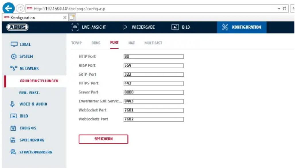
If you wish to enable external access to the camera, the following ports must be configured.
HTTP Port
The default port for HTTP transmission is 80. As an alternative, this port can be assigned a value in the range 1024\~65535. If several cameras are located on the same subnetwork, each camera should have its own unique HTTP port.
RTSP port
The default port for RTSP transmission is 554. As an alternative, this port can be assigned a value in the range 1024\~65535. If several cameras are located on the same subnetwork, each camera should have its own unique RTSP port.
HTTPS Port
The standard port for HTTPS transmission is 443.
Server port
The standard port for SDK transmission is 8000. Communication port for internal data. As an alternative, this port can be assigned a value in the range 1025 \~ 65535. If several IP cameras are located in the same subnetwork, each camera should have its own unique server port.
Advanced SDK Service Port
This port is required for encrypted communication as an alternative to the server port.
WebSocket Port / WebSocket(s) Port
These ports are used for video display in browsers such as Google Chrome or Mozilla Firefox. The installation of a second web plugin is required for this.

Apply the settings by clicking "Save".
8.3.4 NAT
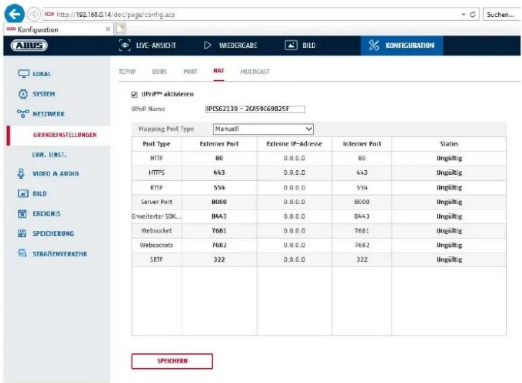
Enable UPnP:
Activation or deactivation of the UPnP interface. Upon activation, the camera, for example, will appear in the Windows network environment.
Name: Definition of the name for the UPnP interface (this name will be assigned to the camera, for example, in the Windows network environment.)
Port Mapping Mode
Select here whether you wish to conduct port mapping automatically or manually. You can choose between "Auto" or "Manual".
Protocol Name:
HTTP
The default port for HTTP transmission is 80. As an alternative, this port can be assigned a value in the range 1025 \~ 65535. If several IP cameras are located on the same subnetwork, each camera should have its own unique HTTP port.
RTSP
The default port for RTSP transmission is 554. As an alternative, this port can be assigned a value in the range 1025 \~ 65535. If several IP cameras are located on the same subnetwork, each camera should have its own unique RTSP port.
Server port (control port)
The standard port for SDK transmission is 8000. Communication port for internal data. As an alternative, this port can be assigned a value in the range 1025 \~ 65535. If several IP cameras are located in the same subnetwork, each camera should have its own unique server port.
External Port
You can only change ports manually here if the "Port Mapping Mode" was set to manual.
Status
Displays whether the external port entered is valid or not valid.
| Not all routers support the UPnP port-mapping function (also know as Auto UPnP). |
8.3.5 Multicast
A multicast server is used to duplicate video streams for access by several clients without placing an additional load on the IP camera.
IP address: IP address of the multicast server
Stream type: Selection of the video stream to be made available to the multicast server
Video connection: Video port
Audio connection: Audio port
8.3.6 SNMP
SNMP v1/2
Enable SNMPv1: Enabling of SNMPv1
Activate SNMPv2: Activation of SNMPv2
Write SNMP Community: SNMP Community string for writing
Read SNMP Community: SNMP Community string for reading
Trap Address: IP address of the TRAP server
Trap Port: Port of the TRAP server
Trap Community: TRAP Community string
SNMP v3
Activate SNMPv3: Activation of SNMPv3
Read user name: Allocate user name
Security level: auth, priv: No authentication, no encryption
auth, no priv.: Authentication, no encryption
no auth, no priv.: No authentication, encryption
Authent. algorithm: Select authentication algorithm: MD5, SDA
Authentication Password: Password assignment
Private-key Algorithm: Select encryption algorithm: DES, AES
Private-key password: Password assignment
Write user name: Allocate user name
Security level: auth, priv: No authentication, no encryption
auth, no priv.: Authentication, no encryption
no auth, no priv.: No authentication, encryption
Auth. algorithm:
Select authentication algorithm: MD5, SDA
Authentication Password: Password assignment
Private-key Algorithm: Select encryption algorithm: DES, AES
Private-key password: Password assignment
SNMP Other Settings
SNMP Port: Network port for the SNMP service
8.3.7 FTP
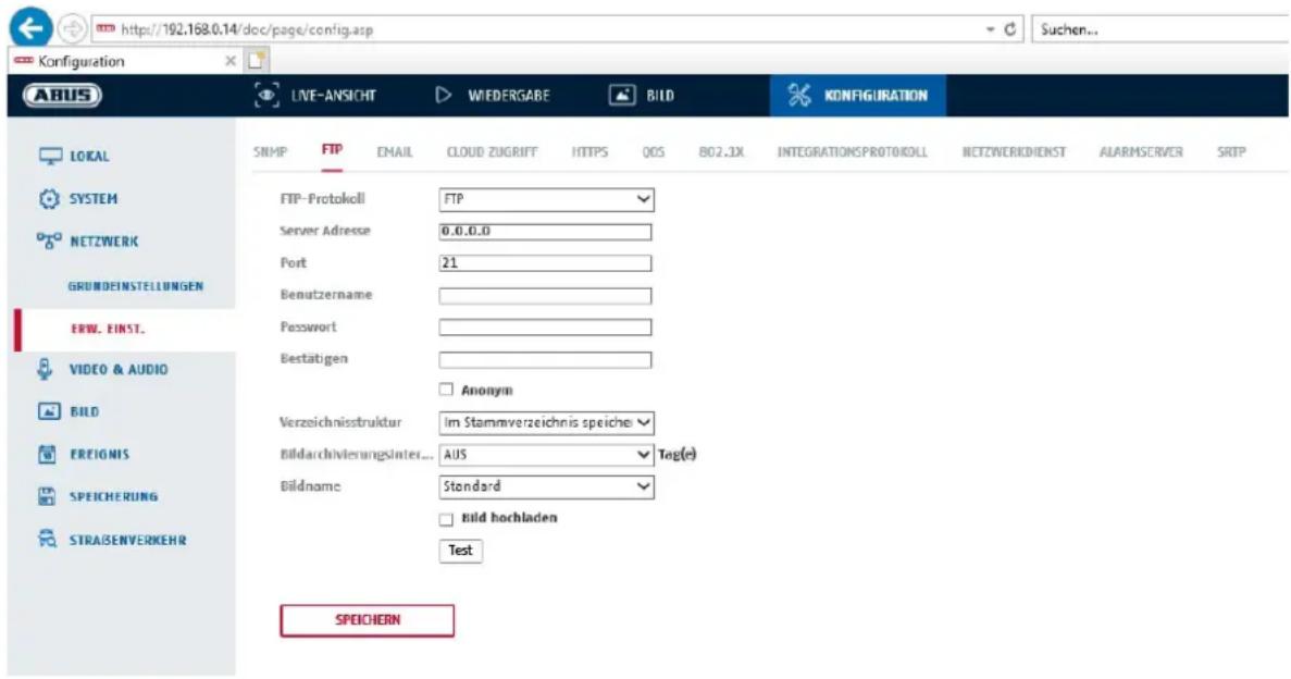
To upload recorded videos or images onto an FTP server, the following settings must be selected.
Server Address
Enter the IP address of the FTP server here.
Port
Enter the port number of the FTP server here. The standard port for FTP servers is 21.
User name
User name of the account that was configured in the FTP server.
Password
Password of the account that was configured in the FTP server.
Confirm
Re-enter the password here.
Directory Structure
Select the save location for the uploaded data here. You can choose between "Save in the root directory."; "Save in the parent directory"; "Save in the child directory".
Parent Directory
This menu item is only available if “Save in the parent directory” or “Save in the child directory” was selected under Directory Structure. You can select the name for the parent directory here. The files are saved in a folder on the FTP server.
Choose between "Use Device Name", "Use Device Number" and "Use Device IP address".
Child Directory
Select the name for the child directory here. The folder is created in the parent directory. You can choose between "Use Camera Name" or "Use Camera Number".
Picture filing interval
This function prevents too many image files from being stored in one folder over time. The server's file system may no longer be able to process or display such a large amount of files.
Example: The setting "2 days" saves images from 2 days in a subfolder. The folder designation in each case is the start and end date of this period.
Image name
The image name can be assigned a user-defined part name at the beginning (prefix).
Upload image
Select "Upload image" to upload images to the FTP server.

Apply the settings by clicking "Save".
8.3.8 Email

You can apply the settings for sending emails here.
Sender
Sender
Enter a name here to be displayed as the sender.
Sender's Address
Enter the email address of the sender here.
SMTP server
Enter the IP address or host name of the SMTP server here. (For example: smtp.googleapis.com)
SMTP port
Enter the SMTP port here. This is configured as 25 by default.
Email encryption
Select the encryption required by the email server (SSL, TLS, STARTTLS)
Interval
Set the interval between sending emails with image attachments here.
Attached Image
Enable this function if images are to be attached to the email in the event of an alarm.
Authentication
If the email server in use requires authentication, enable this function to be able to log onto the server with authentication.
User names and passwords can only be entered once this function has been enabled.
User name
Enter the user name of the email account here. This is the part before the @ symbol.
Password
Enter the password of the email account here.
Confirm
Confirm the password by entering it again.
Receiver
Receiver1 / Receiver2
Enter the name of the receiver here.
Receiver1's Address / Receiver2's Address
Enter the email address of the person to be informed here.

Apply the settings by clicking "Save".
8.3.9 Cloud access / ABUS Link Station
The ABUS Link Station function is used to make it easier to access your ABUS device remotely via the Link Station app (iOS / Android). Products can be easily set up and released via QR code - with no complex configurations in the router (no port forwarding necessary).
Activate the function and assign a verification code (6-12 characters, A-Z, a-z, 0-9, min. 2 different character types recommended).
The QR code can then be photographed in the ABUS Link Station app.
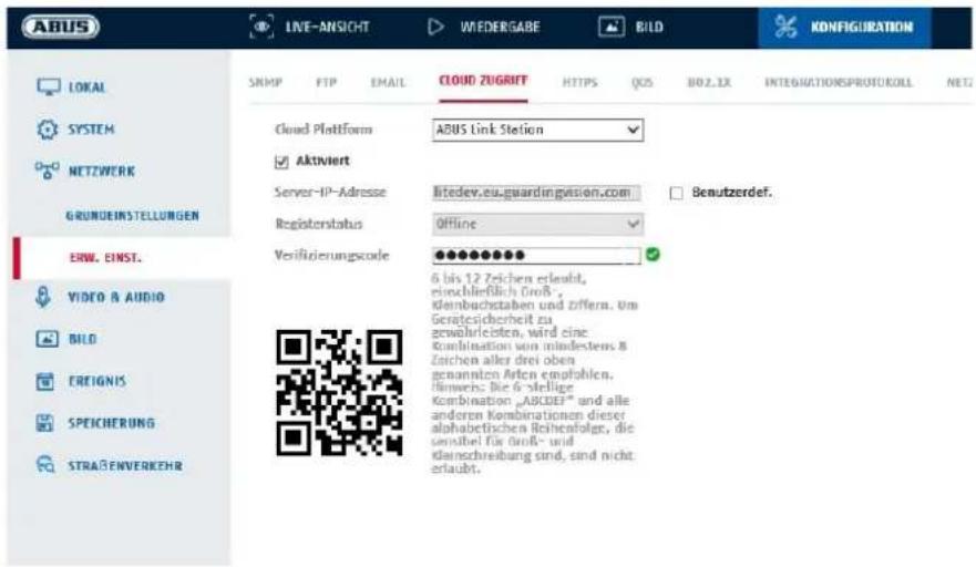
Push function in ABUS Link Station app
- Activate ABUS Link Station function in IP camera
- Add IP camera to ABUS Link Station app via QR code or 9-digit serial number part
- Activate Push notification in app (More/Function settings/Push notification)
- Activate "Alarm notification" in the individual camera settings in the Link Station app.
- Activate and configure the desired detector in the IP camera (Motion detection, Tripwire or Intrusion detection)
- Activate "Event-controlled single frame recording" in IP camera under Storage/Single frame recording/Capture parameters
- Add rule in Event Manager in IP Camera and select "Notify NVR/CMS" as action
Push result in the smartphone:
- Push info in status bar
- 1 single frame under "News" in Link Station app
- optional: with SD card installed and duration or event video recording, short video sequence can also be viewed
8.3.10 HTTPS
Activate HTTPS: enables the HTTPS function. This enables a secure connection with connection certificate. Please note that further steps are necessary for configuring the HTTPS function.
8.3.11 QoS
Video/Audio DSCP: (Differentiated Service Code Point) (0\~63): Priority for video/audio IP packages. The higher the value, the higher the priority.
Event/Alarm DSCP: (0\~63): Priority for event/alarm IP packages. The higher the value, the higher the priority.
Management DSCP: (0\~63): Priority for management IP packages. The higher the value, the higher the priority.
8.3.12 802.1X
Enable IEEE 802.1X: Enable 802.1X authentication
Protocol: Protocol type EAP-MD5 (only)
EAPOL version: Extensible Authentication Protocol over LAN, choice between version 1 or 2
User name: Enter the user name
Password: Enter the password
Confirm: Password confirmation
8.3.13 Integration protocol
In this menu, the ONVIF protocol (Open Network Video Interface) can be activated and configured. For this purpose, an independent user must be created who can then use the ONVIF protocol.
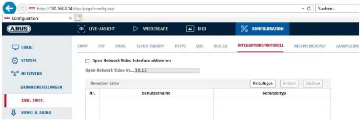
To increase IT security, certain services can be deactivated in this menu item if they are not being used.
8.3.15 Alarm server
In this menu, the transmission of an XML telegram to an HTTP server can be configured. When an event (e.g. motion detection) or smart event (e.g. tripwire) is triggered, this XML telegram is then transmitted and can be further processed in a third-party application.
8.3.16 SRTP
This page contains settings for the SRTP (Secure RTP) streaming settings.
The certificate used and the type of encryption (AES128 or AES256) must be specified.
Procedure (example IP camera via SRTP in ABUS CMS):
- Configure a certificate in the camera (self-signed "default" certificate already exists)
- Configure SRTP with the certificate in the camera.
- Export the certificate from the camera's certificate management to the PC.
- Copy the certificate to the certificate folder of the ABUS CMS software.
- Add the camera to the ABUS CMS software via port 8443 (enable TLS option).
8.4 Video & Audio
8.4.1 Video stream settings

Select the stream type for the camera. Select "Main Stream (Normal)" for recording and live view with good bandwidth. Select "Sub Stream" for live view with restricted bandwidth. A total of 5 video streams are available, but their use depends on the client.
Video Type
This type of camera does not have an audio function. The video type is fixed to "video stream".
Resolution
Set the resolution of the video data here. Depending on the camera model you can choose between 4MPx, 1280*720p; 1280*960; 1920*1080p.
Bitrate Type
Specifies the bitrate of the video stream. The video quality can differ depending on the intensity of movement. You have the choice between a constant bitrate and a variable bitrate.
Video Quality
This menu item is only available if you have selected a variable bitrate. Set the video quality for video data here. The video quality can differ depending on the intensity of movement. You can select from six different video qualities: "Lowest", "Lower", "Low", "Medium", "Higher" or "Highest" (represented by "+").
Frame rate
Specifies the frame rate in frames per second.
Max. Bitrate
The bitrate of the video stream is set to a certain value. Set a max. bitrate of between 32 and 16384 Kbps. A higher value means better video quality; however, this requires more bandwidth.
Video Encoding
Select a standard for video encoding. You can choose between H.264, H.265 and MJPEG.
Profile
Select a profile here. You can choose between 'Basic Profile', 'Main Profile' and 'High Profile'.
I frame interval
Set the I frame interval here. The value must lie between 1 and 400.

Apply the settings by clicking "Save".
8.4.2 Audio
Audio Encoding
select the audio encoding for audio transmission here (G.722.1, G.711ulaw, G.711alaw, MP2L2, G.726).
Audio input
enables the audio input (only for cameras with built-in microphone and microphone input).
Input volume
adjustment of the input amplification for the microphone.
Environmental noise filter
enable the digital noise reduction function for audio transmission here.
8.4.3 ROI (Region of Interest)
The Region-of-Interest function can transmit certain areas in the video image with higher quality than the rest of the video image. This accordingly makes it possible save transmission bandwidth. There is 1 area available for each video stream (1, 2).
Note: The video bit rate of the desired video stream can be set very low (see "Video stream settings").
The selected area in the image is automatically increased to a certain quality level, but the rest of the image remains at low quality/bit rate.
Fixed region: A rectangular frame can be drawn around an area of interest. There is 1 area available for each video stream (1, 2).
ROI level: 1: lower quality of the area, 6: highest quality of the area
Region Name: Assigning a name to the area.
8.4.4 Stream information
Dual VCA:
This function transmits the details of the smart event detectors with the video stream to the NVR. Independent evaluations based on this data can then be carried out in the NVR or CMS, even if the recording was configured as a continuous recording.
8.5 Image
8.5.1 Display settings
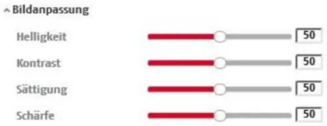
bar
| Category | Value | | ------------ | ----- | | Helligkeit | 50 | | Kontrast | 50 | | Sättigung | 50 | | Schärfe | 50 |Image brightness settings. A value between 0 and 100 can be set.
Contrast
Image contrast settings. A value between 0 and 100 can be set.
Saturation
Image saturation settings. A value between 0 and 100 can be set.
Sharpness
Image sharpness settings. A higher sharpness value can increase image noise.
A value between 0 and 100 can be set.
Exposure Settings
Iris Mode
Exposure parameters can only be set manually for this camera.
Exposure time
Setting the maximum exposure time. This setting is dependent on iris mode.

The higher the speed of the objects in the image, the shorter the exposure time must be set. This reduces the brightness of the image. Additional lighting may then be necessary. A common value for the exposure time for fast-moving objects is 1/250.
Focus
The camera focuses automatically after restarting or after operating the zoom function.
However, the focus can also be adjusted manually afterwards, this is done directly on the live view page. This manually set focal point is then set again even after the camera is restarted, because the camera has saved this point.
Day and night switching
Day/Night Switch
Day/Night Switch provides options for "Auto", "Day" and "Night".
Auto
Depending on the light conditions, the camera switches between day and night mode automatically. The sensitivity can be set between 0 and 7.
Day
In this mode, the camera only outputs colour pictures.

Please note:
Only use this mode if the light conditions remain constant.
Night
In this mode, the camera only outputs black/white pictures.

Please note:
Only use this mode if the light conditions are poor.
Schedule
Sensitivity
Setting for the switching threshold for automatic day/night switching (0–7).
A lower value means that there is a lower lighting level for switching to night mode.
Delay time ("filter time")
Setting a delay time between recognising that a switching is required and carrying out the process.
Smart IR ("Intelligent additional light")
This function can reduce the cross-fade of the video image, in the event that light is reflected from nearby objects.
Additional lighting mode
Depending on your needs, you can choose between "Smart", "IR light" or "white light". The integrated lighting can also be deactivated completely.
Smart: In night mode, the IR light is initially used as additional lighting. The
image is black and white.
At least one event detector (e.g. intrusion detection with person detection) must be programmed.
If the event detector is triggered, the camera switches to color (Gecko) mode. The image now contains color information.
If the event is over, the camera switches back to the light-sensitive IR mode after a delay.
White light (White Supplement Light): In night mode, the white light is used as additional lighting. The image contains color information.
IR light (IR Supplement Light): In night mode, the IR light is used as additional lighting. The image is black and white.
OFF: The additional lighting is completely deactivated. The camera does
not emit any light.
Light brightness control
The general intensity of the lighting can be set.
Auto: Automatic control with maximum value.
Manual: Fixed manual setting
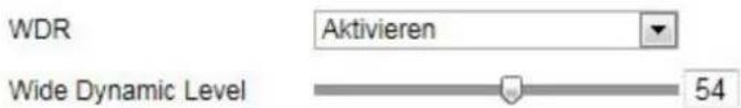
Backlight Settings
WDR
With the aid of the WDR function, the camera can return clear pictures even in disadvantageous backlight conditions. If there are both very bright and very dark areas in the picture area, the brightness level of the overall picture is balanced to provide a clear, detailed image.
Click on the checkbox to enable or disable the WDR function.
Set the Wide Dynamic Level higher to enhance the WDR function.
HLC
(High Light Compensation) Overexposure at the edge of bright light sources is reduced (e.g. car headlights). A higher threshold means high reduction. Function only with deactivated WDR.
White balance
Here you select the lighting conditions in which the camera is installed.
You can choose from the following options: "Manual", "AWB1", "WB Locked", "Fluorescent Lamp", "Incandescent Lamp", "Warm Light", "Natural Light".
Manual
You can adjust the white balance with the following values manually.
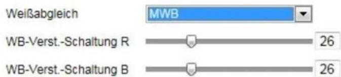
The white balance is performed once and saved.
Other
Use additional white balance options to adjust the function to the light levels.
Fluorescent Lamp
Adjusts the white balance to fluorescent lamp lighting conditions.
Image enhancement
Digital Noise Reduction
You can enable (Normal Mode) or disable the noise reduction.
Noise Reduction Level / 2D/3D DNR
Set the level for noise reduction here.
Grey Scale
This function limits the range of the grey scale representation. This can be beneficial in the case of very light image content.
Video Settings
Mirroring
Three different options for image mirroring are possible (horizontal, vertical, hor. + vert.)
Rotate (Vertical display)
This setting rotates the image to increase the vertical angle of view. It is necessary to rotate the camera module by 90^ when doing this.

Please note:
Rotate (Vertical Display) function is not available in "Smart Event Mode", only in "Surveillance Mode".
Video Standard
Select the video standard corresponding to the available power frequency.
8.5.2 OSD settings

You can use this menu item to select which date and time format are displayed in the live picture.
Display Name
Activate this checkbox if you wish to display the camera name.
Display Date
Activate this checkbox if you wish to display the date in the camera image.
Camera Name
Enter the camera name that is to be displayed in the image here.
Time Format
Choose here whether you would like to display the time in 24-hour or 12-hour format.
Date format
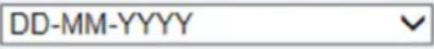
Select the format for the date display here.
(D = day; M = month, Y = year)
Display Mode
Here you can select the display mode for the elements displayed.
You have the following options: "Transparent & Flashing", "Transparent & Not Flashing", "Not Transparent & Flashing", "Not Transparent & Not Flashing".
OSD Size
Here it is possible to adjust the font size of all text overlays.
Font Colour
White, black and self-adapting are available as colours for text overlays. A self-adapting font changes the colour of each digit to either black or white, depending on whether the background is lighter or darker.
Adaptation
This function can be used to set the placement of the text fields as well as the text in the text fields.
Borders left and right
Setting the distances to the left and right edge.
Borders top and bottom
Setting the distances to the top and bottom.

Apply the settings by clicking "Save".
8.5.3 Privacy mask
You can use privacy masks to hide certain areas in the live view to prevent these areas from being recorded and viewed in the live view. A maximum of 4 rectangular privacy masks can be set up in the video image.
Follow the steps below to set up a privacy mask. Select the checkbox
"Enable Privacy Mask". To add a privacy mask, click "Draw Area". You can now select an area on the camera image using your mouse. You can then select three additional areas. By clicking on "Clear All", you can delete all configured privacy masks.

Apply the settings by clicking "Save".
8.5.4 Image parameter change
In the image settings, it is possible to make different settings for different scenes (e.g. different brightness or backlight setting).
These scene settings can now be used or set via a calendar menu for each month and for the hours for each day of that month.
This function helps to compensate for different lighting phases in the different months of the year so that an optimal image can always be achieved.
8.6 Events
8.6.1 Motion detection
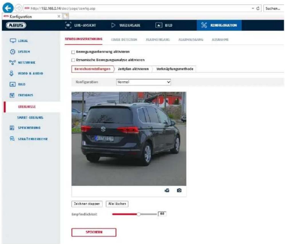
Activate motion detection by clicking the "Enable Motion Detection" checkbox.
Clicking "Enable Dynamic Analysis for Motion" means that movements are recorded in the preview image and the live view (dynamic recording according to motion).
Mode
There are 2 different modes available for marking areas.
Normal: Max. 4 areas, each area as a polygon with max. 10 corners, sensitivity setting is the same for each area
Expert: Max. 8 areas, each area as a rectangle, individual sensitivity setting for each area
To select an area, click the "Set area" button. To discard the selection, click on "clear all".
Click with the left mouse button to define the corners of the polygon, or drag the mouse pointer over the desired area. When drawing the polygons, a right click ends the drawing. For rectangles, click on the "Stop drawing" button.
Set the sensitivity using the regulation control bar.
Detection target
This menu item is the setting for object detection. Object detection detects people and vehicles on a neural basis.
Detection Target
√ Human
Vehicle

-
Object detection (human / vehicle) and the subsequent filtered display of these recordings can only be used in conjunction with an ABUS NVR.
-
On the ABUS NVR, video recordings can be displayed filtered by people or vehicles via the connected monitor (HDMI/VGA) in the "Smart Search" menu. Other motion detection recordings beyond people and vehicles can be displayed in playback as usual.
-
Filtering of the entire motion-controlled recordings according to people and vehicles is also possible in the CMS software of connected ABUS NVRs (event playback).
Sensitivity
Determines the required intensity of the pixel change. The higher the value, the fewer pixel changes are required to trigger motion.
Schedule
To save a schedule for motion-controlled recording, click on "Activate schedule". Specify here on which days of the week and at which times the motion-controlled recording should take place.
The period selection is made by holding down the left mouse button. By clicking on an already marked period, the details can also be set via keypad or deleted again.
To copy the time selection to other weekdays, move the mouse pointer behind the bar of the weekday already set and use the "Copy to ..." function.
Apply the settings made by clicking "Save".
Linkage method
Here you can set the action to be performed following motion detection.
Normal Linkage
Send email: You receive an email as notification; check the checkbox to activate this.
Notify the surveillance centre:
If an event is triggered, the ABUS CMS software can be informed. You may then get a picture pop-up, for example.
Uploading to FTP/Memory card/NAS: Check this check box to upload single frames to an FTP server, the SD card or a connected NAS drive during an event.
Audible warning: This function can output preset or custom tones or sound media.
This requires a camera model with audio output or an integrated loudspeaker.
Trigger alarm output
When an event is triggered, existing alarm outputs on the camera can be activated. The behaviour of the alarm output can be set under "Events / Alarm output".
Trigger recording
Enable this in order to record motion detections onto an SD card.
8.6.2 Cover Detection
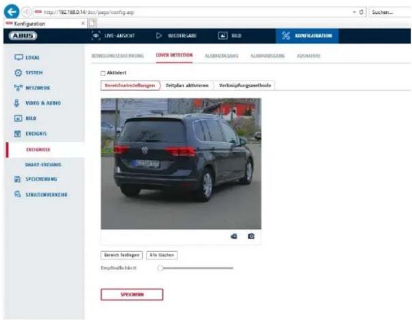
With this menu item you can configure the camera so that video tampering is triggered as soon as the lens is covered (so-called cover detection).
Area settings
Activate video tampering alarm by clicking the "Activate video tampering" checkbox.
To select an area, click on the "Draw Area" button. The entire area is selected by default. To discard this selection, click on "Clear All".
Drag the mouse pointer over the desired area. Set the sensitivity using the regulation control bar. To apply the setting for the area, click on "Stop Drawing".
Right: low sensitivity level. Left: high sensitivity level.
Schedule
To save a schedule, click on "Activate schedule". Specify here on which days of the week and at which times the function should be active.
The period selection is made by holding down the left mouse button. By clicking on an already marked period, the details can also be set via keypad or deleted again.
To copy the time selection to other weekdays, move the mouse pointer behind the bar of the weekday already set and use the "Copy to ..." function.
Apply the settings made by clicking "Save".
Linkage method
Here you can set the action to be performed when an event occurs.
Normal Linkage
Send email: You receive an email as notification; check the checkbox to activate this.
Notify the surveillance centre: Alarm triggering of the NVR/CMS for further processing (e.g.
recording on NVR, or full-screen display when alarm is triggered in CMS)
Trigger alarm output
When an event is triggered, existing alarm outputs on the camera can be activated. The behaviour of the alarm output can be set under "Events / Alarm output".

Apply the settings by clicking "Save".
8.6.3 Alarm input (IPCA54572A)
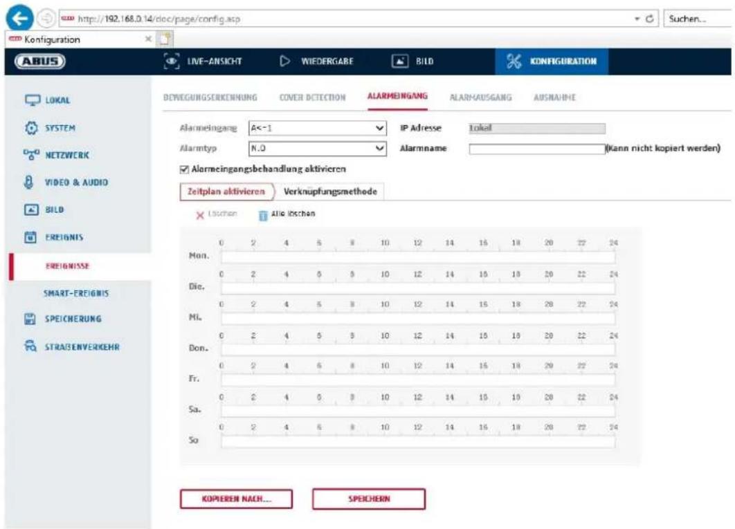
You can configure the camera's alarm input under this menu item
Alarm Input No.
Here you can select the alarm input that you wish to configure.
Alarm name
You can specify a device name for the alarm input here. Please do not use the alarm input number or any special characters.
Alarm Type
Select the alarm type here. You can choose between "NO" (normally open) or "NC" (normally closed).
Schedule
To save a schedule, click on "Activate schedule". Specify here on which days of the week and at which times the alarm input should be active.
The period selection is made by holding down the left mouse button. By clicking on an already marked period, the details can also be set via keypad or deleted again.
To copy the time selection to other weekdays, move the mouse pointer behind the bar of the weekday already set and use the "Copy to ..." function.
Apply the settings made by clicking "Save".
Linkage method
Here you can set the action to be performed when an event occurs.
Normal Linkage
Send email: You receive an email as notification; check the checkbox to activate this.
Notify the surveillance centre:
If an event is triggered, the ABUS CMS software can be informed. You may then get a picture pop-up, for example.
Uploading to FTP/Memory card/NAS: Check this check box to upload single frames to an FTP server, the SD card or a connected NAS drive during an event.
Audible warning: This function can output preset or custom tones or sound media.
This requires a camera model with audio output or an integrated loudspeaker.
Trigger alarm output
When an event is triggered, existing alarm outputs on the camera can be activated. The behaviour of the alarm output can be set under "Events / Alarm output".
Trigger recording
Enable this in order to record motion detections onto an SD card.

Apply the settings by clicking "Save".
8.6.4 Alarm output (IPCA54572A)
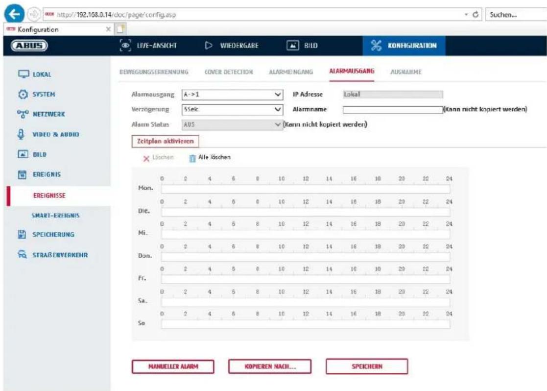
You can configure the two alarm outputs here.
Alarm Output No.
Here, select the alarm output that you wish to configure.
Delay
With the "Manual" setting, the alarm output is not reset after an event. This must then be confirmed and reset manually via the "Manual alarm" button by clicking it twice.
The regular active time of the output after the event is 5 seconds. A further active time of up to 10 minutes can be programmed.
Alarm name
You can specify a name for the relevant alarm output here. Please do not use the alarm output no. or any special characters.
Schedule
To save a schedule, click on "Activate schedule". Specify here on which days of the week and at which times the alarm output should be active.
The period selection is made by holding down the left mouse button. By clicking on an already marked period, the details can also be set via keypad or deleted again.
To copy the time selection to other weekdays, move the mouse pointer behind the bar of the weekday already set and use the "Copy to ..." function.
Apply the settings made by clicking "Save".
8.6.5 Exceptions
Events can trigger the following exceptions:
- HDD full: If the internal SD card or a linked NAS drive is full
- HDD error: SD card or NAS drive error
- Network disconnected: Ethernet cable removed
- IP address conflict
- Illegal login: a reaction can be programmed to follow an incorrect login
The following reactions can be programmed:
- Send email:
- Notify surveillance centre (NVR/CMS)
- Activate alarm output
8.6.6 Flashing Alarm Light Output (IPCA54572A)
The camera has a built-in flash for alarm deterrence.
White Light Mode / Flash mode
Solid: permanently active (for the configured light flash duration)
Flashing: blinking
flash duration
Configuration of the light flash duration from 1-60 seconds
flash rate
The flashing frequency when the flashing option is selected can be set in 3 stages.
brightness
Intensity control for the flashlight
Time schedule
Configuration of the general temporal activity
8.6.7 Audible alarm output (IPCA54572A)
The acoustic alarm output can play predefined sounds or individual short sound media. This function can only be used with a camera with audio output or integrated loudspeaker.
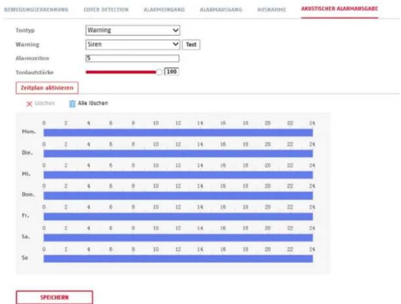
bar
| Event | Count | | :--- | :--- | | Mon. | 0 | | Die. | 0 | | Hi. | 0 | | Don. | 0 | | Fr. | 0 | | Sa. | 0 | | So | 0 | | Category | Count | | :--- | :--- | | Tontyp | Warning | | Warning | Siren | | Alarmzeiten | 5 | | Tonlautstärke | 100 | | Alles löschen | Count | | :--- | :--- | | Mon. | 2 | | Die. | 2 | | Hi. | 2 | | Don. | 2 | | Fr. | 2 | | Sa. | 2 | | So | 2 | | SPEICHERN | Count | | :--- | :--- | | Mon. | 24 | | Die. | 24 | | Hi. | 24 | | Don. | 24 | | Fr. | 24 | | Sa. | 24 | | So | 24 |Sound type: Warning (warning tone, selection), Prompt (short acoustic indication), User-defined audio (from file)
A more detailed setting of the selected option is made in the next menu item.
Warning: Select an acoustic message from the list (English-language messages)
User-def. audio: Add: Selecting the audio file (Format: *.wav file, max. 512 KByte file size, sampling rate 8 kHz)
Converting an audio file into the corresponding format can be done using an online converter or freeware software.
Alarm time: Playback duration
Sound volume: Playback volume
Schedule: Schedule definition (procedure is the same as setting other schedules)
8.6.8 Intrusion detection
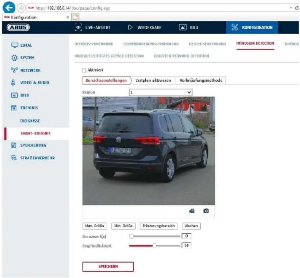
Enable intrusion detection: The intrusion detection function triggers an event if an object stays in the area to be monitored for longer than the set time.
Preview video: configure the area to be monitored
Max. size: This function determines the maximum size of the object to be detected. This is done by drawing a rectangle in the preview video. The rectangle can be drawn anywhere in the preview video.
Min. size: This function determines the minimum size of the object to be detected. This is done by drawing a rectangle in the preview video. The rectangle can be drawn anywhere in the preview video.
Detection area: The area to be monitored can be drawn in the video image (quadrilateral area). Operation: Press button -> set corner points using left mouse button (max. 4) -> press right mouse button to finish drawing
Delete: delete the area.
Detection target
This menu item is the setting for object detection. Object detection detects people and vehicles on a neural basis.
Detection Target
√ Human
√ Vehicle

- When using object detection, video recordings on the internal SD card only contain recordings of detected people or vehicles. Other objects do not resolve a recording on the SD card.
| 2. When using object detection and recording the video data to an ABUS NVR, all intruding objects are first saved as a recording. Filtering can be done subsequently via the ABUS NVR (local operator interface) or the CMS software (LAN/WAN).3. Object detection (human / vehicle) and the subsequent filtered display of these recordings can only be used in conjunction with an ABUS NVR.4. On the ABUS NVR, video recordings can be displayed filtered by people or vehicles via the connected monitor (HDMI/VGA) in the "Smart Search" menu. Other motion detection recordings beyond people and vehicles can be displayed in playback as usual.5. Filtering of the entire motion-controlled recordings according to people and vehicles is also possible in the CMS software of connected ABUS NVRs (event playback). |
Region: Number of available areas: 4
Threshold: The higher the value (0-10 seconds), the longer an object has to stay in the area to be monitored in order to trigger an event.
Sensitivity: higher sensitivity allows smaller objects to be detected.
Schedule
To save a schedule, click on "Activate schedule". Specify here on which days of the week and at which times the alarm output should be active.
The period selection is made by holding down the left mouse button. By clicking on an already marked period, the details can also be set via keypad or deleted again.
To copy the time selection to other weekdays, move the mouse pointer behind the bar of the weekday already set and use the "Copy to ..." function.
Apply the settings made by clicking "Save".
Linkage method
Here you can set the action to be performed when an event occurs.
Normal Linkage
Send email: You receive an email as notification; check the checkbox to activate this.
Notify the surveillance centre:
If an event is triggered, the ABUS CMS software can be informed. You may then get a picture pop-up, for example.
Uploading to FTP/Memory card/NAS: Check this check box to upload single frames to an FTP server, the SD card or a connected NAS drive during an event.
Audible warning: This function can output preset or custom tones or sound media.
This requires a camera model with audio output or an integrated loudspeaker.
Trigger alarm output
When an event is triggered, existing alarm outputs on the camera can be activated. The behaviour of the alarm output can be set under "Events / Alarm output".
Trigger recording
Enable this in order to record motion detections onto an SD card.
8.6.9 Tripwire
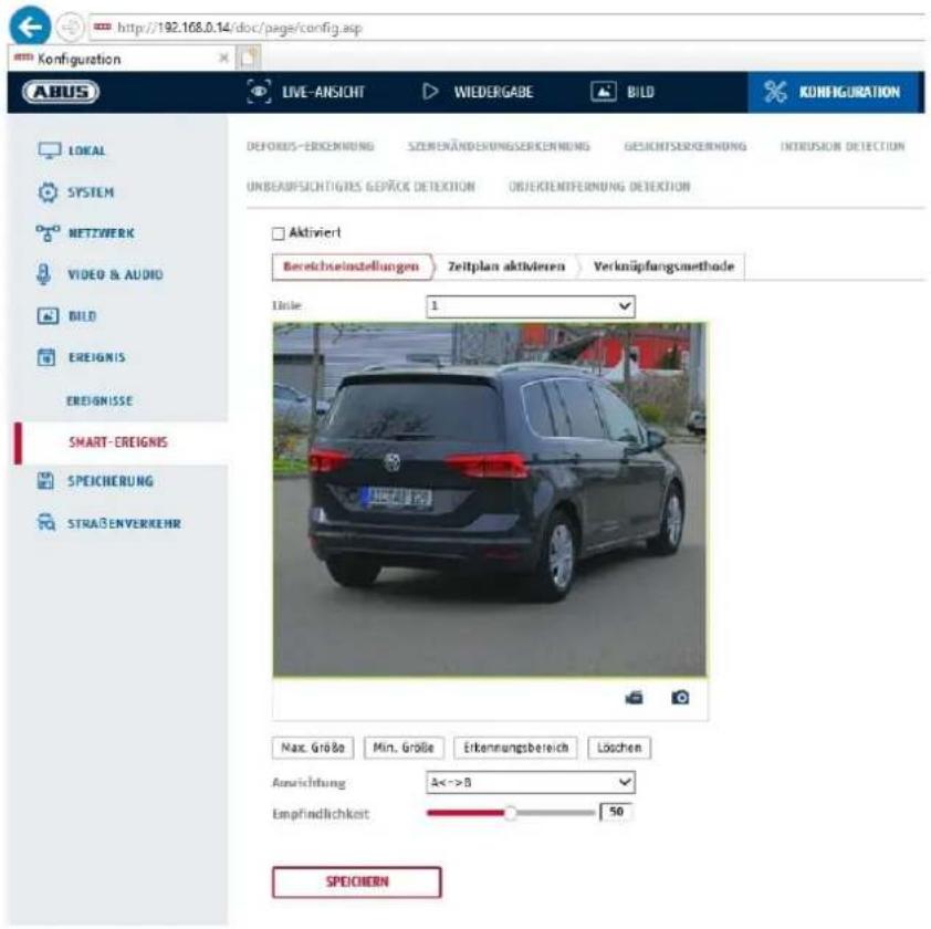
The tripwire function detects whether an object crosses a virtual line in the video image in a certain direction or both directions. Then, an event can be triggered.
Preview video: configure the virtual line here.
Max. size: This function determines the maximum size of the object to be detected.
This is done by drawing a rectangle in the preview video. The rectangle can be drawn anywhere in the preview video.
Min. size: This function determines the minimum size of the object to be detected.
This is done by drawing a rectangle in the preview video. The rectangle can be drawn anywhere in the preview video.
Drawing: a virtual line appears in the preview video after the button is pressed. It is
then possible to click on this line and move it using the mouse and the red corner points. "A" and "B" indicate the directions.
Line: number of available virtual lines: 4
Delete: delete the virtual line
Detection target
This menu item is the setting for object detection. Object detection detects people and vehicles on a neural basis.
Detection Target
√ Human
Vehicle

-
When using object detection, video recordings on the internal SD card only contain recordings of detected people or vehicles. Other objects do not resolve a recording on the SD card.
-
When using object detection and recording the video data to an ABUS NVR, all intruding objects are first saved as a recording. Filtering can be done subsequently via the ABUS NVR (local operator interface) or the CMS software (LAN/WAN).
-
Object detection (human / vehicle) and the subsequent filtered display of these recordings can only be used in conjunction with an ABUS NVR.
-
On the ABUS NVR, video recordings can be displayed filtered by people or vehicles via the connected monitor (HDMI/VGA) in the "Smart Search" menu. Other motion detection recordings beyond people and vehicles can be displayed in playback as usual.
-
Filtering of the entire motion-controlled recordings according to people and vehicles is also possible in the CMS software of connected ABUS NVRs (event playback).
Direction: definition of the direction(s) in which an object crosses and triggers an event.
Sensitivity: The higher the value, the earlier a crossing object is detected.
Schedule
To save a schedule, click on "Activate schedule". Specify here on which days of the week and at which times the alarm output should be active.
The period selection is made by holding down the left mouse button. By clicking on an already marked period, the details can also be set via keypad or deleted again.
To copy the time selection to other weekdays, move the mouse pointer behind the bar of the weekday already set and use the "Copy to ..." function.
Apply the settings made by clicking "Save".
Linkage method
Here you can set the action to be performed when an event occurs.
Normal Linkage
Send email: You receive an email as notification; check the checkbox to activate this.
Notify the surveillance centre: If an event is triggered, the ABUS CMS software can be informed. You may then get a picture pop-up, for example.
Uploading to FTP/Memory card/NAS: Check this check box to upload single frames to an FTP server, the SD card or a connected NAS drive during an event.
Audible warning: This function can output preset or custom tones or sound media.
This requires a camera model with audio output or an integrated loudspeaker.
Trigger alarm output
When an event is triggered, existing alarm outputs on the camera can be activated. The behaviour of the alarm output can be set under "Events / Alarm output".
Trigger recording
Enable this in order to record motion detections onto an SD card.
8.6.10 Area input detection
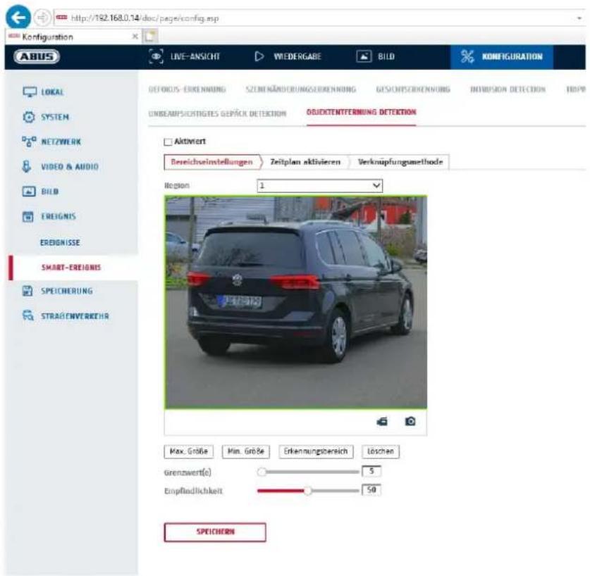
This function detects the entry of an object into a marked area and immediately triggers an event.
Preview video: configure the area to be monitored
Max. size: This function determines the maximum size of the object to be detected. This is done by drawing a rectangle in the preview video. The rectangle can be drawn anywhere in the preview video.
Min. size: This function determines the minimum size of the object to be detected. This is done by drawing a rectangle in the preview video. The rectangle can be drawn anywhere in the preview video.
Detection area: The area to be monitored can be drawn in the video image (quadrilateral area). Operation: Press button -> set corner points using left mouse button (max. 4) -> press right mouse button to finish drawing
Delete: delete the area.
Detection target
This menu item is the setting for object detection. Object detection detects people and vehicles on a neural basis.
Detection Target
√ Human
√ Vehicle

-
When using object detection, video recordings on the internal SD card only contain recordings of detected people or vehicles. Other objects do not resolve a recording on the SD card.
-
When using object detection and recording the video data to an ABUS NVR, all intruding objects are first saved as a recording. Filtering can be done subsequently via the ABUS
| NVR (local operator interface) or the CMS software (LAN/WAN).3. Object detection (human / vehicle) and the subsequent filtered display of these recordings can only be used in conjunction with an ABUS NVR.4. On the ABUS NVR, video recordings can be displayed filtered by people or vehicles via the connected monitor (HDMI/VGA) in the "Smart Search" menu. Other motion detection recordings beyond people and vehicles can be displayed in playback as usual.5. Filtering of the entire motion-controlled recordings according to people and vehicles is also possible in the CMS software of connected ABUS NVRs (event playback). |
Region: Number of available areas: 4
Sensitivity: higher sensitivity allows smaller objects to be detected.
Schedule
To save a schedule, click on "Activate schedule". Specify here on which days of the week and at which times the alarm output should be active.
The period selection is made by holding down the left mouse button. By clicking on an already marked period, the details can also be set via keypad or deleted again.
To copy the time selection to other weekdays, move the mouse pointer behind the bar of the weekday already set and use the "Copy to ..." function.
Apply the settings made by clicking "Save".
Linkage method
Here you can set the action to be performed when an event occurs.
Normal Linkage
Send email: You receive an email as notification; check the checkbox to activate this.
Notify the surveillance centre: If an event is triggered, the ABUS CMS software can be informed. You may then get a picture pop-up, for example.
Uploading to FTP/Memory card/NAS: Check this check box to upload single frames to an FTP server, the SD card or a connected NAS drive during an event.
Audible warning: This function can output preset or custom tones or sound media. This requires a camera model with audio output or an integrated loudspeaker.
Trigger alarm output
When an event is triggered, existing alarm outputs on the camera can be activated. The behaviour of the alarm output can be set under "Events / Alarm output".
Trigger recording
Enable this in order to record motion detections onto an SD card.
8.6.11 Area output detection
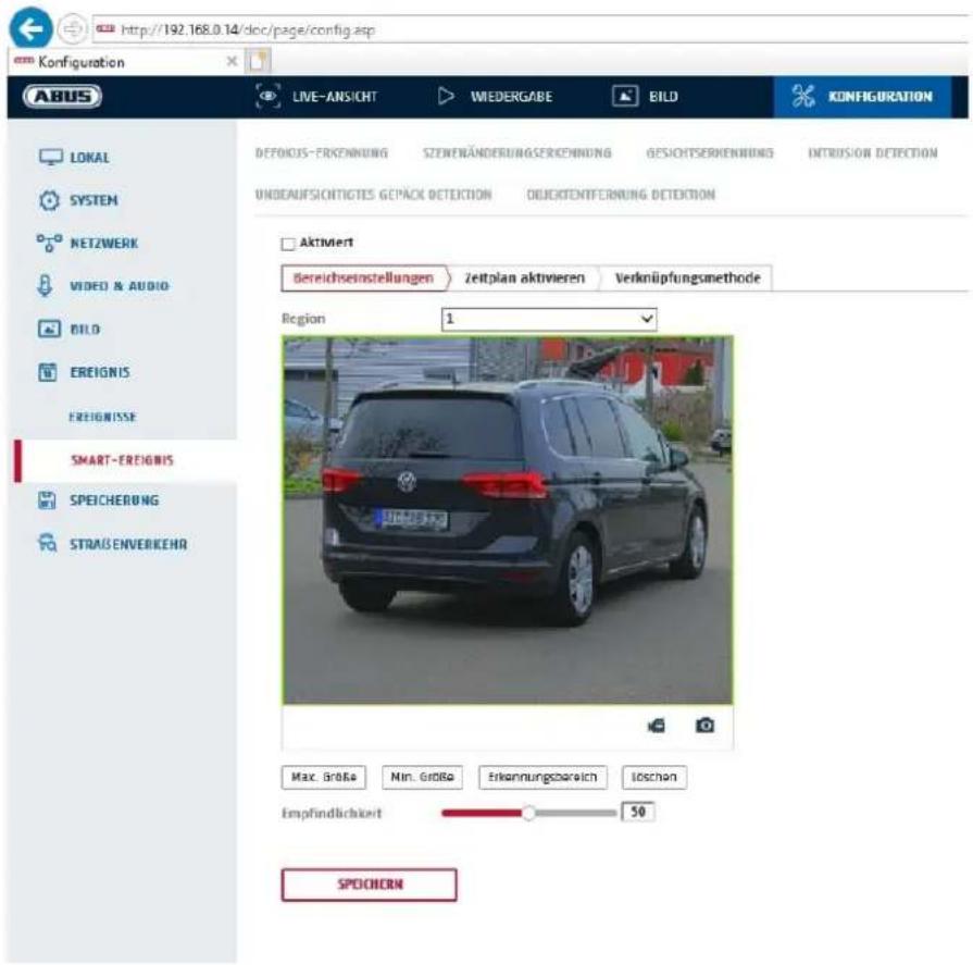
This function detects the exit of an object into a marked area and immediately triggers an event.
Preview video: configure the area to be monitored
Max. size: This function determines the maximum size of the object to be detected. This is done by drawing a rectangle in the preview video. The rectangle can be drawn anywhere in the preview video.
Min. size: This function determines the minimum size of the object to be detected. This is done by drawing a rectangle in the preview video. The rectangle can be drawn anywhere in the preview video.
Detection area: The area to be monitored can be drawn in the video image (quadrilateral area). Operation: Press button -> set corner points using left mouse button (max. 4) -> press right mouse button to finish drawing
Delete: delete the area
Region: Number of available areas: 4
Detection target
This menu item is the setting for object detection. Object detection detects people and vehicles on a neural basis.
Detection Target
√ Human
Vehicle

- When using object detection, video recordings on the internal SD card only contain recordings of detected people or vehicles. Other objects do not resolve a recording on the SD card.
| 2. When using object detection and recording the video data to an ABUS NVR, all intruding objects are first saved as a recording. Filtering can be done subsequently via the ABUS NVR (local operator interface) or the CMS software (LAN/WAN).3. Object detection (human / vehicle) and the subsequent filtered display of these recordings can only be used in conjunction with an ABUS NVR.4. On the ABUS NVR, video recordings can be displayed filtered by people or vehicles via the connected monitor (HDMI/VGA) in the "Smart Search" menu. Other motion detection recordings beyond people and vehicles can be displayed in playback as usual.5. Filtering of the entire motion-controlled recordings according to people and vehicles is also possible in the CMS software of connected ABUS NVRs (event playback). |
Sensitivity: higher sensitivity allows smaller objects to be detected.
Schedule
To save a schedule, click on "Activate schedule". Specify here on which days of the week and at which times the alarm output should be active.
The period selection is made by holding down the left mouse button. By clicking on an already marked period, the details can also be set via keypad or deleted again.
To copy the time selection to other weekdays, move the mouse pointer behind the bar of the weekday already set and use the "Copy to ..." function.
Apply the settings made by clicking "Save".
Linkage method
Here you can set the action to be performed when an event occurs.
Normal Linkage
Send email: You receive an email as notification; check the checkbox to activate this.
Notify the surveillance centre: If an event is triggered, the ABUS CMS software can be informed. You may then get a picture pop-up, for example.
Uploading to FTP/Memory card/NAS: Check this check box to upload single frames to an FTP server, the SD card or a connected NAS drive during an event.
Audible warning: This function can output preset or custom tones or sound media.
This requires a camera model with audio output or an integrated loudspeaker.
Trigger alarm output
When an event is triggered, existing alarm outputs on the camera can be activated. The behaviour of the alarm output can be set under "Events / Alarm output".
Trigger recording
Enable this in order to record motion detections onto an SD card.
8.7 Storage
8.7.1 Record schedule
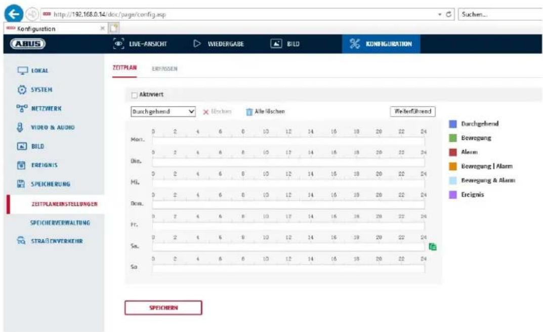
Here, you can set the configuration for time and event-triggered recordings in order to be able to save them to an SD card.
Post-record
Set the duration for recording of the image data after a basic event here.
Overwrite
Here, you can set whether the recordings should be automatically overwritten if the storage capacity is full.
Elapsed time: With this function it is possible to limit how long data is stored for on the SD card.
Schedule
To save a schedule, click on "Activate schedule". Specify here on which days of the week and at which times the alarm output should be active.
The period selection is made by holding down the left mouse button. By clicking on an already marked period, the details can also be set via keypad or deleted again.
To copy the time selection to other weekdays, move the mouse pointer behind the bar of the weekday already set and use the "Copy to ..." function.
Apply the settings made by clicking "Save".
Under Record Type, select the recording mode for the desired schedule. You can
choose between the following recording types:
Normal: Continuous recording
Motion: motion-triggered recording.
Alarm: Alarm input (if available)
Motion detection | Alarm: recording triggered by motion or by alarm input. Camera begins recording either following motion detection or an alarm input.
Motion detection & Alarm: recording triggered by motion and by alarm input. Camera only starts recording if motion and alarm input are triggered simultaneously.
Event: Recording of all smart events (e.g. Tripwire)

Please note that the alarm input is only available in certain models.
To apply the changes, click "OK" and to discard them click "Cancel".
8.7.2 Capture / Single frame
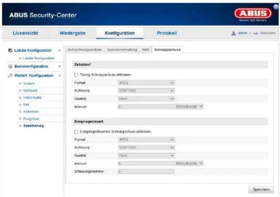
You can configure time and event-triggered snapshots here to upload them to an FTP server.
Timing
Enable Timing Snapshot
Enable this function to save images at certain intervals.
Format
The format for the pictures is preconfigured as JPEG.
Resolution
Set the resolution of the picture here.
Quality
Select the quality for the saved pictures here.
Interval
Set the interval to occur between the saving of two pictures here.
Event-Triggered
Enable Event-Triggered Snapshot
Enable this function to save event-triggered pictures.
Format
The format for the pictures is preconfigured as JPEG.
Resolution
Set the resolution of the picture here.
Quality
Select the quality for the saved pictures here.
Interval
Set the interval to occur between the saving of two pictures here.
8.7.3 Storage Management
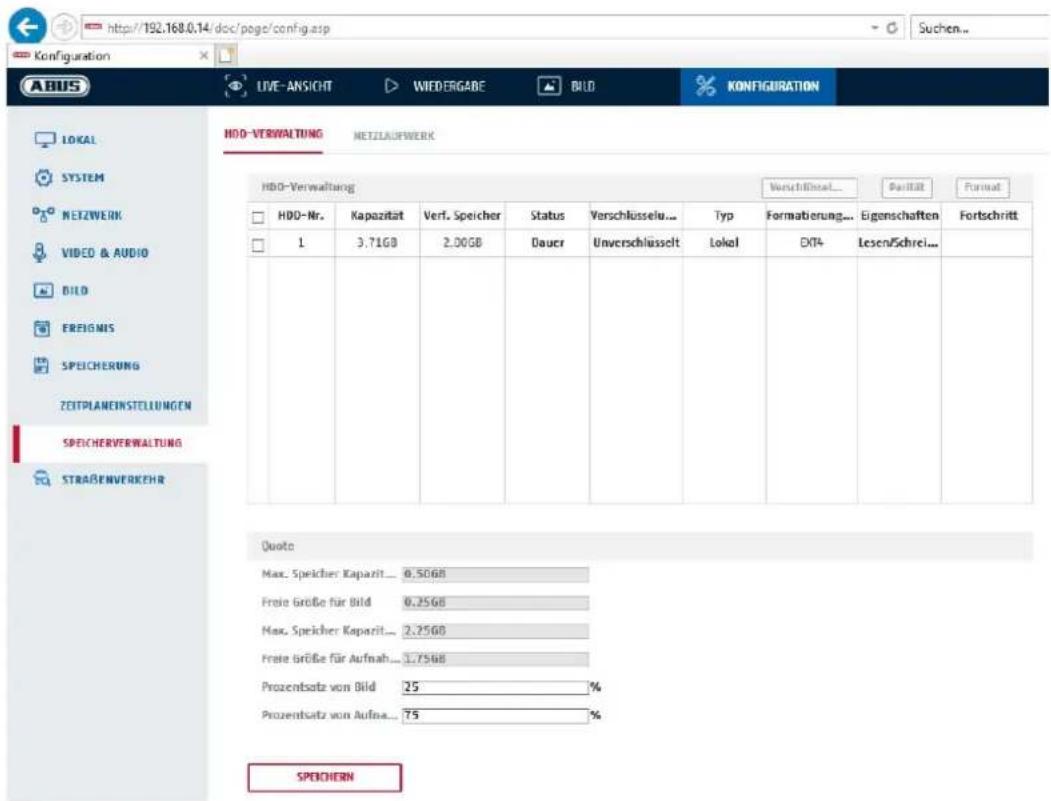
Here you can format the inserted microSD card and display its properties. Furthermore, the data on the storage medium can be encrypted. A percentage distribution of the storage space of video data and single frames can also be made.
First set all the desired options and parameters and then format the storage medium.
8.7.4 NAS
This menu can be used to set the NAS storage locations; these are then available in the camera as a drive (HDD) for storage.
Server Address IP address of the NAS drive
File Path: path on the NAS drive
9. Maintenance and cleaning
9.1 Maintenance
Regularly check the technical safety of the product, e.g. check the housing for damage.
If it appears to no longer be possible to operate the product safely, stop using it and secure it to prevent unintentional use.
It is likely that safe operation is no longer possible in the event that:
- the device shows signs of visible damage
- the device no longer works correctly

Please note:
You do not need to perform any maintenance on the product. There are no components to service and nothing inside the product to check. Never open it.
9.2 Cleaning
Clean the product with a clean, dry cloth. The cloth can be dampened with lukewarm water to remove stubborn dirt.

Do not allow any liquids to enter the device.
Do not use any chemical cleaning products as they could damage the surface of the housing and screen (discolouration).
10. Disposal
Attention: EU Directive 2002/96/EC regulates the proper return, treatment and recycling of used electronic devices. This symbol means that, in the interest of environmental protection, the device must be disposed of separately from household or industrial waste at the end of its lifespan in accordance with applicable local legal guidelines. Used devices can be disposed of at official recycling centres in your country. Obey local regulations when disposing of material. Further details on returns (also for non-EU countries) can be obtained from your local authority. Separate collection and recycling conserve natural resources and ensure that all the provisions for protecting health and the environment are observed when recycling the product.
11. Technical data
More technical information on each individual camera is available via the product search at www.abus.com.
12. Open Source Licence information
We also wish to inform you at this point that the network surveillance camera, among others, includes open source software. Please read the open source licence information enclosed with the product.
IPCA34\*\*\* / IPCA54\*\*\* / IPCA64\*\*\*
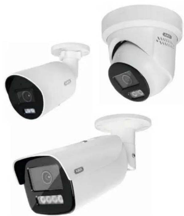
natural_image
Three white surveillance cameras with digital display screens, shown from different angles (no text or symbols visible)Mode d'emploi
Version 09/2024
CE
8.1 Configuration locale
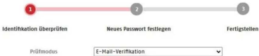
8.4 Vidéo et audio
natural_image
Three white surveillance cameras with digital displays and camera modules, shown from different angles (no text or symbols visible)6.9 De camera integreren in de ABUS Link Station app
Over P2P Cloud Funtion:
100M full-dup; 10M/100M/1000M auto
DHCP
Veroudering. DNS-server
8.4 Video en audio
8.4.1 Instellingen videostream

Wit licht (White Supplement Light):
natural_image
Three white surveillance cameras with digital display screens, shown from different angles (no text or symbols visible)8.7 Opbevaring....360
8.7.1 Optagelsesplan 360
8.7.2 Optagelse / enkeltbillede....361
8.7.3 Hukommelsesstyring....362
8.7.4 NAS....362
6.6 Startside (login-side)
Gem live snapshot under
flowchart
graph LR
    A["1"] --> B["2"]
    B --> C["3"]
    D["Prüfmodus"] --> E["E-Mail-Verification"]

8.3 Netværk
8.3.1 TCP/IP

8.4 Video og lyd
8.4.1 Indstillinger for videostream
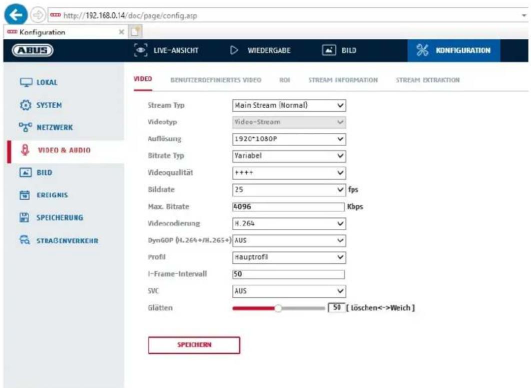
natural_image
Three white surveillance cameras with digital displays and security camera modules, shown from different angles (no text or symbols visible)
100M full-dup; 10M/100M/1000M auto
DHCP
8.3.9 Accesso al cloud / ABUS Link Station
Funzione push in ABUS Link Station APP
8.4 Video e audio

- IPCA34\*\*\* / IPCA54\*\*\* / IPCA64\*\*\*
- Bedienungsanleitung
- DHCP
- SNMP v3
- Video & Audio
- Video Stream Einstellungen
- Zeitplan
- Operating instructions
- Introduction
- Disclaimer
- Explanation of symbols
- Important safety information
- The following safety information and hazard notes are not only intended to protect your health, but also to protect the device from damage. Please read the following points carefully:
- Safety information
- Warnings
- Unpacking the device
- Contents
- Network 107
- Video & Audio 118
- Image 120
- Events....126
- Storage 142
- Maintenance and cleaning 145
- Disposal....145
- Technical data....146
- Open Source Licence information 146
- Intended use
- Explanation of symbols
- Features and functions
- Device description
- Description of the connections
- Initial start-up
- Using the ABUS IP Installer for camera search
- Accessing the network camera via a web browser
- General instructions for using the settings pages
- Installing video plugin
- Initial password assignment
- Home page (login page)
- User accounts and passwords
- Connecting the camera to ABUS NVR
- Connecting the camera to ABUS Link Station app
- Connecting the camera to ABUS CMS
- Notes for installation when using object detection
- User functions
- Menu bar
- Live image display
- Control bar
- Playback
- Image
- Local configuration
- Protocol
- Live view performance
- Live Indicator (Rules Information)
- Image format
- Record file settings
- Recording file size
- Save recordings to
- Save downloaded files to
- Image save settings
- Save snapshots in live view to
- Save snapshots during playback to
- Save clips to
- System
- System settings
- Basic information
- Model:
- Serial No.:
- Firmware version:
- Encoding version:
- Number of Channels:
- Number of HDDs/SDs:
- Number of Alarm Input:
- Number of Alarm Output:
- Time settings
- Time setting methods
- NTP
- Server Address
- NTP Port
- NTP update interval
- Manual Time Sync.
- Device time
- Set time
- DST / Summer Time
- Start time
- End time
- RS-232
- VCA Resource
- Meta Data Settings
- About / Licence information
- Maintenance
- Upgrade and maintenance
- Standard
- Restore
- Import Config. File
- Config File
- Status
- Export Config. File
- Remote Upgrade
- Firmware
- Automatic restart
- Protocol
- Security Audit Protocol
- Security
- Authentication
- IP address filter
- Enable IP address filter
- IP Address Filter Type
- MAC address filter
- Security service
- Enable illegal login lock
- Enhanced security
- Certificate Management
- Managing users
- User name
- User type
- Password
- Confirm
- Online users
- Account security settings
- NIC settings
- IPv4 address
- IPv4 Subnet Mask
- IPv4 Default Gateway
- IPv6 Mode
- IPv6 Address
- IPv6 Subnet mask
- IPv6 Standard gateway
- MAC address
- MTU
- DNS Server
- Preferred DNS server
- Alternative DNS Server
- Domain name settings
- DDNS
- Port
- HTTP Port
- RTSP port
- HTTPS Port
- Server port
- Advanced SDK Service Port
- WebSocket Port / WebSocket(s) Port
- NAT
- Port Mapping Mode
- Protocol Name:
- HTTP
- RTSP
- Server port (control port)
- External Port
- Multicast
- SNMP
- SNMP v1/2
- SNMP Other Settings
- FTP
- Port
- Directory Structure
- Parent Directory
- Child Directory
- Picture filing interval
- Image name
- Upload image
- Sender
- Sender's Address
- SMTP server
- SMTP port
- Email encryption
- Interval
- Attached Image
- Authentication
- Receiver
- Receiver1 / Receiver2
- Receiver1's Address / Receiver2's Address
- Cloud access / ABUS Link Station
- Push function in ABUS Link Station app
- HTTPS
- QoS
- 802.1X
- Integration protocol
- Alarm server
- SRTP
- Video stream settings
- Video Type
- Resolution
- Bitrate Type
- Video Quality
- Frame rate
- Max. Bitrate
- Video Encoding
- Profile
- I frame interval
- Audio
- Audio Encoding
- Audio input
- Input volume
- Environmental noise filter
- ROI (Region of Interest)
- Stream information
- Image
- Display settings
- Contrast
- Saturation
- Sharpness
- Exposure Settings
- Iris Mode
- Exposure time
- Focus
- Day and night switching
- Day/Night Switch
- Auto
- Day
- Please note:
- Night
- Schedule
- Sensitivity
- Delay time ("filter time")
- Smart IR ("Intelligent additional light")
- Additional lighting mode
- Light brightness control
- Backlight Settings
- WDR
- HLC
- White balance
- Manual
- Other
- Fluorescent Lamp
- Image enhancement
- Digital Noise Reduction
- Noise Reduction Level / 2D/3D DNR
- Grey Scale
- Video Settings
- Mirroring
- Rotate (Vertical display)
- Video Standard
- OSD settings
- Display Name
- Display Date
- Camera Name
- Time Format
- Date format
- Display Mode
- OSD Size
- Font Colour
- Adaptation
- Borders left and right
- Borders top and bottom
- Privacy mask
- Image parameter change
- Events
- Motion detection
- Mode
- Detection target
- Linkage method
- Normal Linkage
- Trigger alarm output
- Trigger recording
- Cover Detection
- Area settings
- Alarm input (IPCA54572A)
- Alarm Input No.
- Alarm name
- Alarm Type
- Alarm output (IPCA54572A)
- Alarm Output No.
- Delay
- Exceptions
- Flashing Alarm Light Output (IPCA54572A)
- White Light Mode / Flash mode
- flash duration
- flash rate
- brightness
- Time schedule
- Audible alarm output (IPCA54572A)
- Intrusion detection
- Tripwire
- Area input detection
- Area output detection
- Storage
- Record schedule
- Post-record
- Overwrite
- Capture / Single frame
- Timing
- Enable Timing Snapshot
- Format
- Quality
- Event-Triggered
- Enable Event-Triggered Snapshot
- Storage Management
- NAS
- Maintenance and cleaning
- Maintenance
- Cleaning
- Disposal
- Technical data
- Open Source Licence information
- Mode d'emploi
- Configuration locale
- Vidéo et audio
- De camera integreren in de ABUS Link Station app
- Veroudering. DNS-server
- Video en audio
- Instellingen videostream
- Opbevaring....360
- Startside (login-side)
- Gem live snapshot under
- Netværk
- TCP/IP
- Video og lyd
- Indstillinger for videostream
- Accesso al cloud / ABUS Link Station
- Funzione push in ABUS Link Station APP
- Video e audio
Brand : ABUS
Model : IPCA54512B
Category : Surveillance Camera