
HDCC78551 - Surveillance Camera ABUS - Free user manual and instructions
Find the device manual for free HDCC78551 ABUS in PDF.

| Product Type | Outdoor HD-TVI surveillance camera |
| Brand | ABUS |
| Model | HDCC78551 |
| Resolution | 4K (3840 x 2160) at 12.5 fps |
| Lens | Motorized, varifocal 2.8 to 12 mm |
| Night vision | Integrated IR LEDs, range depends on conditions |
| WDR function | True WDR 120 dB to balance contrasts |
| Noise reduction | DNR (adjustable 3DNR) |
| Protection rating | IP67 (weather-resistant) |
| Power supply | 12 V DC or 24 V AC (non-polarity) |
| Video output | HD-TVI on BNC connector (RG59 type, up to 500 m) |
| Day/night switching | Automatic via photodetector, or manual |
| OSD menu | Configuration via ABUS HD-TVI DVR (coaxial cable) |
| Mounting | On wall, ceiling, or wall mount (optional) |
| Orientation | 3 axes: tilt 70°, pan 340°, rotation 320° |
| Cleaning | Dry or slightly damp cloth, no chemicals |
| Safety | Do not open, surge protection recommended |
| Maintenance | No parts requiring maintenance |
| Compliance | EMC directives 2014/30/EU and RoHS 2011/65/EU |
| Included accessories | Installation tool, adapter, drilling template |
Frequently Asked Questions - HDCC78551 ABUS
User questions about HDCC78551 ABUS
0 question about this device. Answer the ones you know or ask your own.
Ask a new question about this device
Download the instructions for your Surveillance Camera in PDF format for free! Find your manual HDCC78551 - ABUS and take your electronic device back in hand. On this page are published all the documents necessary for the use of your device. HDCC78551 by ABUS.
USER MANUAL HDCC78551 ABUS
natural_image
Exterior view of a white ASUS security camera (no visible text or symbols on body)natural_image
Exterior view of a white Atlas security camera (no text or symbols visible on body)Bedienungsanleitung
Version 12/2023
CE
natural_image
Technical diagram of a mechanical assembly with gears and housing (no text or labels)natural_image
Technical line drawing of a mounted device with internal components and wiring (no text or symbols)natural_image
Technical diagram of a mechanical assembly with no visible text or symbols6. Bildschirmmenü
natural_image
Front view of a white ASIS security camera with visible lens and aperture (no text or symbols on body)User guide
Version 12/2023
CE
English translation of the original German instruction manual. Retain for future reference.
Introduction
Dear customer,
Thank you for purchasing this product.
The device complies with the requirements of the following EU directives: EMC Directive 2014/30/EU and the RoHS Directive 2011/65/EU.
To ensure this condition is maintained and that safe operation is guaranteed, it is your obligation to observe this user guide.
Please read the entire user guide carefully before putting the product into operation, and pay attention to all operating instructions and safety information.
All company names and product descriptions are trademarks of the corresponding owner. All rights reserved.
If you have any questions, please contact your specialist installation contractor or specialist dealer.

Disclaimer
This user guide has been produced with the greatest of care. Should you discover any omissions or inaccuracies however, please inform us in writing at the address provided on the back of the manual. ABUS Security-Center GmbH & Co. KG assumes no liability for technical and typographical errors, and reserves the right to make changes to the product and user manuals at any time and without prior notice. ABUS Security-Center GmbH is not liable or responsible for direct or indirect damage resulting from the equipment, performance and use of this product. No guarantee is made for the contents of this document.
Explanation of symbols
 | The triangular high voltage symbol is used to warn of the risk of injury or health hazards (e.g. caused by electric shock). |
 | The triangular warning symbol indicates important notes in this user guide which must be observed. |
 | This symbol indicates special tips and notes on the operation of the unit. |
Important safety information
 | All guarantee claims are invalid in the event of damage caused by non-compliance with this user guide. We cannot be held liable for resulting damage. |
 | We cannot be held liable for material or personal damage caused by improper operation or non-compliance with the safety information. All guarantee claims are void in such cases. |
The following safety information and hazard notes are not only intended to protect your health, but also to protect the device from damage. Please read the following points carefully:
- There are no components inside the product that require servicing. Dismantling the product invalidates the CE certification and the guarantee/warranty.
- The product may be damaged if it is dropped, even from a low height.
- Install the device so that the image sensor is not subjected to direct sunlight. Pay attention to the installation instructions in the corresponding section of this user manual.
- The device is designed for indoor and outdoor use (IP67).
Avoid the following adverse conditions during operation:
- Moisture or excess humidity
• Extreme heat or cold - Direct sunlight
• Dust or flammable gases, vapours or solvents
• Strong vibrations
• Strong magnetic fields (e.g. near machines or loudspeakers). - The camera must not be installed on unstable surfaces.
General safety information:
- Do not leave packaging material lying around. Plastic bags, sheeting, polystyrene packaging, etc. can pose a danger to children if played with.
- The video surveillance camera contains small parts which could be swallowed and must be kept out of the reach of children for safety reasons.
- Do not insert any objects into the device through the openings.
- Only use replacement devices and accessories that are approved by the manufacturer. Do not connect any non-compatible products.
- Please pay attention to the safety information and user manuals for the other connected devices.
- Check the device for damage before putting it into operation. Do not put the device into operation if you identify any damage.
- Adhere to the normal voltage limits specified in the technical data. Higher voltages could destroy the device and pose a health risk (electric shock).
Safety information
- Power supply: Note the information provided on the type plate for supply voltage and power consumption.
- Overloading
Avoid overloading electrical sockets, extension cables and adapters, as this can result in fire or electric shock.
- Cleaning
Only use a damp cloth to clean the device. Do not use corrosive cleaning materials. Disconnect the device from the power supply before cleaning.
Warnings
Observe all safety and operating instructions before putting the device into operation for the first time.
-
Observe the following information to avoid damage to the power cable and plug:
-
Do not pull the cable when disconnecting the device from the power – always take hold of the plug.
-
Ensure that the power cable is positioned as far away as possible from any heating equipment, as this could otherwise melt the plastic coating.
-
Follow these instructions. Non-compliance with these instructions could lead to electric shock:
-
Never open the housing or power supply unit.
-
Do not insert any metallic or flammable objects into the device.
• Use surge protection to prevent damage caused by overvoltage (e.g. in electrical storms). -
Disconnect defective devices from the power immediately and contact your specialist dealer.
 | When installing the device in an existing video surveillance system, ensure that all devices have been disconnected from the mains power circuit and low-voltage circuit. |
 | If in doubt, have a specialist technician carry out assembly, installation and connection of the device. Improper or unprofessional work on the mains network or domestic installations puts both you and others at risk.Connect the installations so that the mains power circuit and low-voltage circuit always run separately from each other. They should not be connected at any point or become connected as a result of a malfunction. |
Unpacking the device
Handle the device with extreme care when unpacking it.
| If the original packaging has been damaged, inspect the device. If the device shows signs of damage, return it in the original packaging and inform the delivery service. |
Contents
- Intended use....25
- Scope of delivery 25
- Features and functions......25
- Camera description ......26
- Installation....27
5.1. Mounting the camera....27
5.2. Orientation of the camera....28
5.3. Power supply....28
5.4. Connecting the video cable .....28
5.5. Installation on the wall mount 29
5.6 Installation on a suspended ceiling....29 - On-screen display....31
6.1. Opening the on-screen display....31
6.2. Description of the on-screen display....31 - Maintenance and cleaning ....35
7.1. Maintenance....35
7.2. Cleaning....35 - Disposal....35
- Technical data....36
1. Intended use
This camera is designed for both daytime and night-time use. It provides video images in HD resolution. The output signal is provided in HD-TVI format. This allows the use of a conventional coaxial cable for signal transmission. It is used for video surveillance in conjunction with a recording device. The device is designed for indoor and outdoor use.
2. Scope of delivery
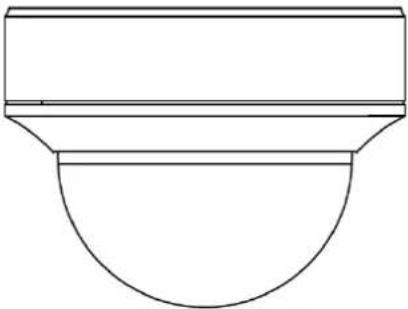 | 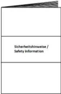 |
| Outdoor HD-TVI vario dome | Safety information |
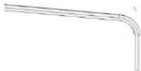 | 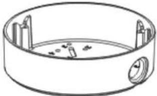 |
| Installation tool Installation adapter | |
 | |
| Drilling template |
3. Features and functions
• 4K resolution: 3840 x 2160 @ 12.5 fps (HDCC78551)
• Transmission via conventional CCTV infrastructure (up to 500 m via RG59 cable)
• Motor-controlled Vario lens, 2.8–12 mm
• IR LEDs for night vision
• DNR for noise-free images
• True WDR function to compensate for image contrasts (120 dB)
• Weatherproof camera housing (IP67)
- On-screen display for camera configuration (control via DVR via coaxial cable)
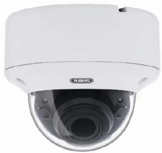
4. Camera description
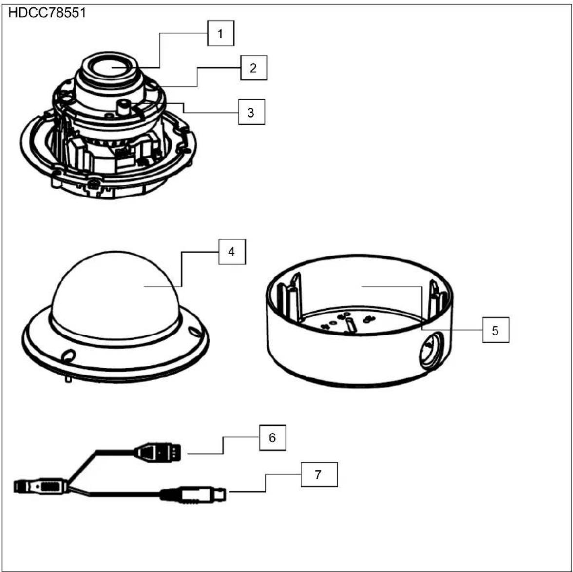
| 1 | Camera module with lens |
| 2 | Infrared LED (2, to the left and right of the lens) |
| 3 | Photo sensor for day/night switching |
| 4 | Dome |
| 5 | Installation adapter for surface mounting |
| 6 | Power supply (12 VDC or 24 VAC, 2-pin connection, polarity does not need to be observed) |
| 7 | HD-TVI video output (BNC, labelled 'TVI') |
5. Installation
5.1. Mounting the camera

IMPORTANT!
The camera must be disconnected from the power supply during installation.
Use the accompanying drilling template for drilling the mounting holes for the installation adapter. An opening is provided on the installation adapter for cabling at the side. A cable gland must be used (M25x1.5) for cabling at the side. Use screw anchors and screws that are appropriate to the surface to fix the installation adapter in place.
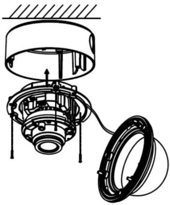
Now remove the camera dome from the camera module. Use the hexagon wrench provided to do this.

To simplify installation, a retaining rope with eye is provided in the installation adapter to allow the camera module to be suspended.
Now guide the connecting cable through the installation adapter and either into the ceiling or through the side opening.
The connection to the installation cable can be made inside the installation adapter if required.
natural_image
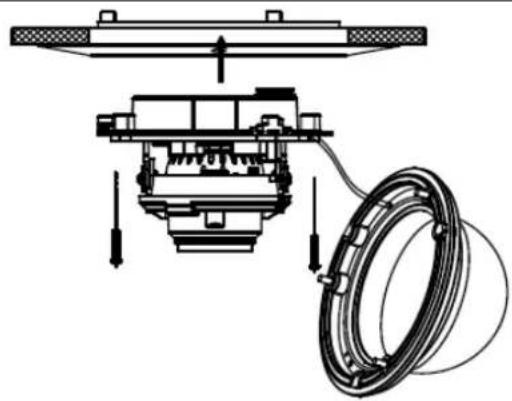
Mechanical assembly diagram showing a bearing housing and rotating components (no text or labels)Now insert the camera module into the installation adapter. When doing so, ensure that the guide rail and guide notch of the installation adapter and camera module fit correctly. It is only then that the camera module is in the correct position.

Now retighten the fixing screws of the camera module.
After orienting the camera module, attach the camera cap and camera dome.

Now fix the camera dome in place.
5.2. Orientation of the camera
| The camera module can be oriented in three axes. | |
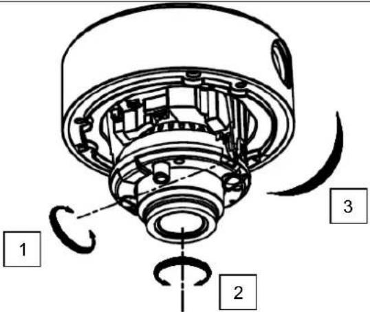 | 1: Tilt 70°2: Rotation 340°3: Pivot 320° |

The IR range is strongly dependent on the environmental conditions. If the area in the camera's field of view reflects poorly or if there are no objects within the max. illumination range, the brightness of the video image at night may be too low. This will result in poor usability of the video image.
In addition, when installing the camera it must be ensured that no objects are located in close proximity to the camera's field of view (e.g. roof gutter or wall). These objects can reflect back the IR light, resulting in circular fading on the video image in the opposite direction to the object.
5.3. Power supply
| IMPORTANT!Before starting installation, ensure that the power supply voltage and the rated voltage of the camera are identical. |
The cameras require a 12 V DC or 24 V AC power supply. The polarity of the DC voltage supply does not need to be observed!
5.4. Connecting the video cable
In order to transmit the HD-TVI video signal from the camera to a recorder, an RG59 type coaxial cable with BNC connector (male) must be connected to the connection labelled 'TVI'. The cable length to the next device must not exceed 500 m (RG59).
 | To ensure optimum quality of the HD-TVI signal transmission, it is important that the cable is neither kinked nor crushed at any point, and that its radius is adequate (min. bending radius 6 cm).Damage to the cable or porosity as a result of ageing can have a negative impact on the quality of the signal or image (e.g. shadowing around the edges). |
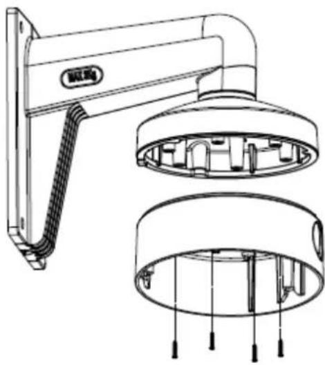
5.5. Installation on the wall mount
- First drill the four holes in the wall to attach the wall mount to the wall.
- Use appropriate screw anchors and screws to attach the wall mount to the wall.
- Screw the round adapter plate on to the wall mount. Secure the adapter using a side fixing screw.
- Attach the installation adapter to the wall mount.
- Run all cables through the wall mount and connect them correctly to the camera module.
- You can now carry out the subsequent steps as previously described in the section on installation.

The appropriate TVAC31320 wall mount is required for the installation. This is not included in the scope of delivery of the camera.
natural_image
Technical line drawing of a wall-mounted device with internal components and wiring (no text or symbols)5.6 Installation on a suspended ceiling
The following installation data must be observed:
Installation depth (min.): 50 mm
Diameter of camera insert:
min. 145 mm (max. 152 mm)
Diameter for fixings: 10 mm
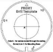
- First, create an opening of min. 145 mm to max. 152 mm at the desired location in the suspended ceiling.
- Glue the drilling template to the opening in the ceiling in a central position.
- Drill three holes with a diameter of approx. 10 mm in the places marked.
- Screw the three long metric screws supplied through the three outer fixing holes in the ceiling recessing ring.
- Then screw the three spreading clamps on to the three metric screws from the back.
- Insert the ceiling recessing ring into the feed-through and the three spreading clamps into the fixing holes and push the spreading clamps through the fixing holes. The spreading clamps should now hold the ceiling recessing ring to the ceiling.
- Next fasten the three fixing screws until the ceiling recessing ring is finally level and firmly attached to the ceiling.
- The camera module can then be installed and oriented in the same way as during the installation in the installation adapter, and the dome can be placed on top.
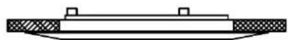

The appropriate TVAC31360 recessing ring is required for the installation. This is not included in the scope of delivery of the camera.
The required installation depth is min. 5 cm.
natural_image
Technical diagram of a mechanical assembly with no visible text or symbols6. On-screen display
6.1. Opening the on-screen display
This camera's on-screen display can be opened via the ABUS HD-TVI DVR. Please consult the user manual for the ABUS HD-TVI DVR.
6.2. Description of the on-screen display
Pressing the on-screen display control button opens the on-screen display. This on-screen display allows you to adjust a number of detailed settings.
| Main Menu |
| Video Format <8MP@12.5FPS> |
| Language English |
| Settings ↓ |
| Save&Exit |
| Function | Description |
| Video Format | Video resolution settingOptions:8 megapixel @ 15 frames per second8 megapixel @ 12.5 frames per second5 megapixel @ 20 frames per second4 megapixel @ 25 frames per second4 megapixel @ 30 frames per second2 megapixel @ 25 frames per second2 megapixel @ 30 frames per second |
| Language | Setting for the language of the on-screen displayFor this camera model, English is currently the only available language. |
| Settings | Advanced camera settingsPress the ENTER button to open the advanced camera settings menu. |
| Save&Exit | Save and exit the menu |
MAIN MENU
Exposure
This menu item allows you to adjust general exposure settings, e.g. whether the camera should process high contrasts or whether the camera requires special settings for night vision.
| Function | Description |
| Brightness | (1~10): Picture brightness setting |
| Exposure Mode | Global: General automatic exposure setting without WDR functionBLC: Automatic exposure setting with backlight compensation. The BLC function enhances the image display in the event of medium image contrast levels.WDR: Automatic exposure setting with WDR function (wide dynamic range). The WDR function enables improved display of high image contrasts. This function also has a four-step setting for adjusting to the respective contrast conditions.HLC: This function reduces overexposure caused by very bright light sources. |
| AGC | Automatic gain control. As the setting is increased, the video image appears lighter in poor lighting conditions, although the higher the setting the higher the image noise.Off: DeactivatedLow: LowMedium: MediumHigh: High |
| Slow Shutter | (Off~X4): Continuous exposure setting. Longer exposure times for each image make the resulting image lighter. However, this results in a reduction in the frame rate (the longer the exposure time, the lower the frame rate).Off: deactivatedX2/X4: Exposure time increased by a factor of x |
| Back | Return to previous menu screen |
| Save&Exit | Save and exit the menu |
White Balance
This menu item allows you to adjust the white balance settings.
| Function | Description |
| Auto | Automatic white balance |
| manual, handbook, guide, instructions | Manual white balanceR Gain: Gain factor for proportion of red in imageB Gain: Gain factor for proportion of blue in imageBack: Return to previous menu screenSave&Exit: Save and exit the menu |
DAY NIGHT
This menu item allows you to set the mode for day/night switching.
| Function | Description |
| Auto | Automatic activation/deactivation of day mode or night mode. The integrated photo sensor controls the switchover according to the lighting level.IR Light: On: IR LEDs activated in night modeOff: IR LEDs deactivated in night modeSmart IR: Function for reducing overexposure of IR lightwith close objectsOn: Function activatedOff: Function deactivatedD->N Threshold (1–9): Switching threshold from day to night modeN->D Threshold (1–9): Switching threshold from night to day modeBack: Return to previous menu screen |
| Colour | The camera stays in colour mode permanently. The infrared cut filter is constantly in front of the lens, and the IR LEDs are constantly off. |
| B&W | The camera stays in black/white mode permanently. The infrared cut filter is constantly separated from the lens. The IR LEDs are switched on and off automatically by the photo sensor. |
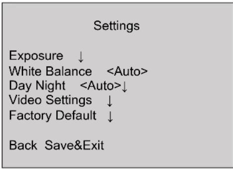
Video Settings
This menu item allows you to adjust general image settings, such as contrast or video image mirroring.
| Function | Description |
| Contrast | (0~10): Image contrast setting |
| Sharpness | (0~10): This function allows image sharpness perception to be adjusted electronically. |
| Saturation | (0~10): Saturation of the video image |
| 3DNR | (0~10): Noise reduction function setting. The higher the value set, the more noise will be removed from the video image by the software. |
| Mirror | Mirroring of the video imageOff: DeactivatedHV: Horizontal and vertical image mirroring (standard)V: Vertical image mirroringH: Horizontal image mirroring |
| Defog | (0–4): Function for improving the contrast. A higher value increases the image noise. |
| RETURN | Return to previous menu screen |
Factory Default (Reset)
| Function | Description |
| Factory Default | Reset all camera settings in the main menu to the factory settingsOk: Confirm processCancel: Cancel process |
Back
| Function | Description |
| Back | Return to previous menu screen |
Save&Exit
| Function | Description |
| Save&Exit | Save all settings and exit the on-screen display |
7. Maintenance and cleaning
7.1. Maintenance
Regularly check the technical safety of the product, e.g. check the housing for damage.
If it appears to no longer be possible to operate the product safely, stop using it and secure it to prevent unintentional use.
It is likely that safe operation is no longer possible in the event that:
- the device shows signs of visible damage
• the device no longer works correctly

Please note:
You do not need to perform any maintenance on the product. There are no components to service and nothing inside the product to check. Never open it.
7.2. Cleaning
Clean the product with a clean, dry cloth. The cloth can be dampened with lukewarm water to remove stubborn dirt.

Do not allow any liquids to enter the device.
Do not use any chemical cleaning products as they could damage the surface of the housing and screen (discolouration).
8. Disposal
Important: EU Directive 2002/96/EC regulates the proper return, treatment and recycling of used electronic devices. This symbol means that, in the interest of environmental protection, the device must be disposed of separately from household or industrial waste at the end of its lifespan in accordance with applicable local legal guidelines. Used devices can be disposed of at official recycling centres in your country. Obey local regulations when disposing of material. Further details on returns (also for non-EU countries) can be obtained from your local authority. Separate collection and recycling conserve natural resources and ensure that all the provisions for protecting health and the environment are observed when recycling the product.
9. Technical data
More technical information on each individual camera is available via the product search at www.abus.com.

The IR range is strongly dependent on the environmental conditions. If the area in the camera's field of view reflects poorly or if there are no objects within the max. illumination range, the brightness of the video image at night may be too low. This will result in poor usability of the video image.
In addition, when installing the camera it must be ensured that no objects are located in close proximity to the camera's field of view (e.g. roof gutter or wall). These objects can reflect back the IR light, resulting in circular fading on the video image in the opposite direction to the object.
HDCC78551
natural_image
Front view of a white ARUS security camera with lens and control buttons (no visible text or symbols on body)natural_image
Technical diagram of a mechanical assembly with gears and housing (no text or labels)natural_image
Technical line drawing of a mounted device with internal components and wiring (no text or symbols)natural_image
Technical diagram of a mechanical assembly with no visible text or symbolsnatural_image
Front view of a white ABIS security camera with lens and aperture (no visible text or symbols)natural_image
Mechanical assembly diagram showing a bearing housing and rotating wheel (no text or labels)natural_image
Technical line drawing of a wall-mounted device with internal components and wiring (no text or symbols)natural_image
Technical diagram of a mechanical assembly with no visible text or symbols6. Schermmenu
6.1. Schermmenu (OSD) openen
natural_image
Front view of a white ARUS security camera with visible lens and control buttons (no text or symbols on body)natural_image
Technical diagram of a mechanical assembly with gears and housing (no text or labels)natural_image
Technical line drawing of a wall-mounted device with internal components and wiring (no text or symbols)natural_image
Technical diagram of a mechanical assembly with no visible text or symbols6. Skæmmenu
natural_image
Front view of a white ABIS security camera with lens and control panel (no visible text or symbols)natural_image
Mechanical assembly diagram showing a bearing housing and rotating components (no text or labels)natural_image
Technical line drawing of a wall-mounted device with internal components and wiring (no text or symbols)natural_image
Technical diagram of a mechanical assembly with no visible text or symbols6. Menu su schermo
6.1. Apertura del menu su schermo (OSD)
- Bedienungsanleitung
- Bildschirmmenü
- User guide
- Introduction
- Disclaimer
- Explanation of symbols
- Important safety information
- Safety information
- Warnings
- Unpacking the device
- Contents
- Intended use
- Scope of delivery
- Features and functions
- Camera description
- Installation
- Mounting the camera
- IMPORTANT!
- Orientation of the camera
- Power supply
- Connecting the video cable
- Installation on the wall mount
- Installation on a suspended ceiling
- On-screen display
- Opening the on-screen display
- Description of the on-screen display
- MAIN MENU
- Exposure
- White Balance
- DAY NIGHT
- Video Settings
- Maintenance and cleaning
- Maintenance
- Please note:
- Cleaning
- Disposal
- Technical data
- HDCC78551
- Schermmenu
- Schermmenu (OSD) openen
- Skæmmenu
- Menu su schermo
- Apertura del menu su schermo (OSD)
Brand : ABUS
Model : HDCC78551
Category : Surveillance Camera