USER MANUAL PRO800 BEHRINGER
PRO-800
Classic Analog 8-Voice Polyphonic Synthesizer with 2 VCOs, Classic VCF, Arpeggiator, Sequencer and 400 Program Memories in Eurorack Format
23Quick Start GuidePRO 800
EN

Important Safety Instructions
ES
Terminals marked with this symbol carry electrical current of sufficient magnitude to constitute risk of electric shock. Use only high-quality professional speaker cables with 1/4" TS or twist-locking plugs pre-installed. All other installation or modification should be performed only by qualified personnel.
This symbol, wherever it appears, alerts you to the presence of uninsulated dangerous voltage inside the enclosure - voltage that may be sufficient to constitute a risk of shock.
This symbol, wherever it appears, alerts you to important operating and maintenance instructions in the accompanying literature. Please read the manual.
Caution
To reduce the risk of electric shock, do not remove the top cover (or the rear section). No user serviceable parts inside. Refer servicing to qualified personnel.
Caution
To reduce the risk of fire or electric shock, do not expose this appliance to rain and moisture. The apparatus shall not be exposed to dripping or splashing liquids and no objects filled with liquids, such as vases, shall be placed on the apparatus.
Caution
These service instructions are for use by qualified service personnel only. To reduce the risk of electric shock do not perform any servicing other than that contained in the operation instructions Repairs have to be performed by qualified service personnel.

Warning
Please refer to the
information on the
exterior of bottom enclosure for electrical and safety information before installing or operating the device.
-
Please read and follow all instructions and warnings.
-
Keep the apparatus away from water (except for outdoor products).
-
Clean only with dry cloth.
-
Do not block ventilation openings. Do not install in a confined space. Install only according to manufacturer's instructions.
-
Protect the power cord from damage, particularly at plugs and appliance socket.
-
Do not install near any heat sources such as radiators, heat registers, stoves or other apparatus (including amplifiers) that produce heat.
-
Do not defeat the safety purpose of the polarized or grounding-type plug. A polarized plug has two blades with one wider than the other (only for USA and Canada). A grounding-type plug has two blades and a third grounding prong. The wide blade or the third prong are provided for your safety. If the provided plug does not fit into your outlet, consult an electrician for replacement of the obsolete outlet.
-
Use only attachments and accessories recommended by the manufacturer.

- Use only specified carts, stands, tripods, brackets, or tables. Use caution to prevent tip-over
when moving the cart/apparatus combination.
-
Unplug during storms, or if not in use for a long period.
-
Only use qualified personnel for servicing, especially after damage.
-
The apparatus with protective earthing terminal shall be connected to a MAINS socket outlet with a protective
earthing connection.
-
Where the MAINS plug or an appliance coupler is used as the disconnect device, the disconnect device shall remain readily operable.
-
Avoid installing in confined spaces like bookcases.
-
Do not place naked flame sources, such as lighted candles, on the apparatus.
-
Operating temperature range 5° to 45°C (41° to 113°F).
LEGAL DISCLAIMER
Music Tribe accepts no liability for any loss which may be suffered by any person who relies either wholly or in part upon any description, photograph, or statement contained herein. Technical specifications, appearances and other information are subject to change without notice. All trademarks are the property of their respective owners. Midas, Klark Teknik, Lab Gruppen, Lake, Tannoy, Turbosound, TC Electronic, TC Helicon, Behringer, Bugera, Aston Microphones and Coolaudio are trademarks or registered trademarks of Music Tribe Global Brands Ltd. © Music Tribe Global Brands Ltd. 2024 All rights reserved.
LIMITED WARRANTY
For the applicable warranty terms and conditions and additional information regarding Music Tribe's Limited Warranty, please see complete details online at community.musictribe.com/support.
ES
BESCHRÄNKTE GARANTIE
Keyboard Amplifier
Band/Practice System
16 17 Quick Start GuidePRO 800
PRO-800 Controls
EN Step 2: Controls
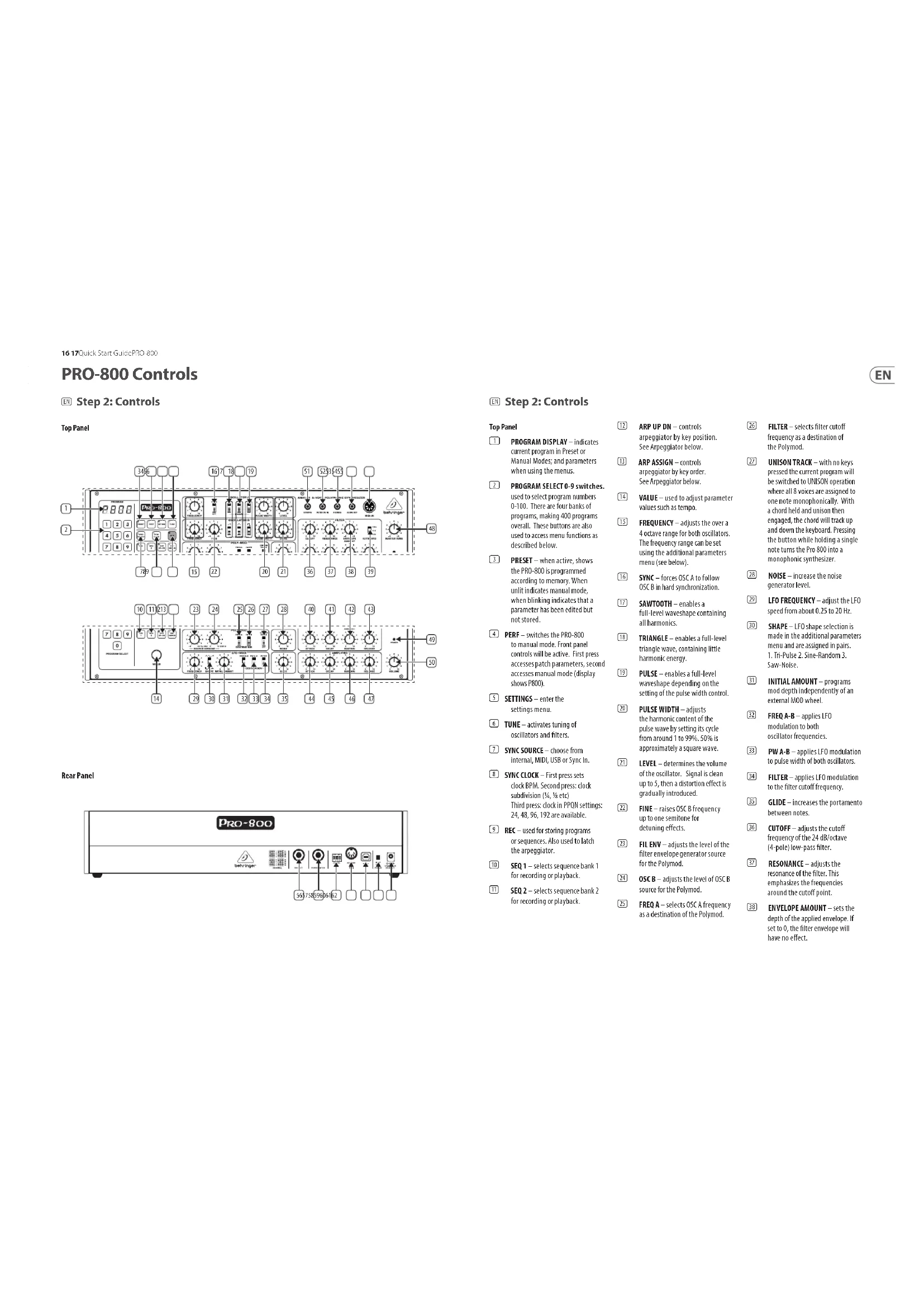
Top Panel

Rear Panel
EM Step 2: Controls
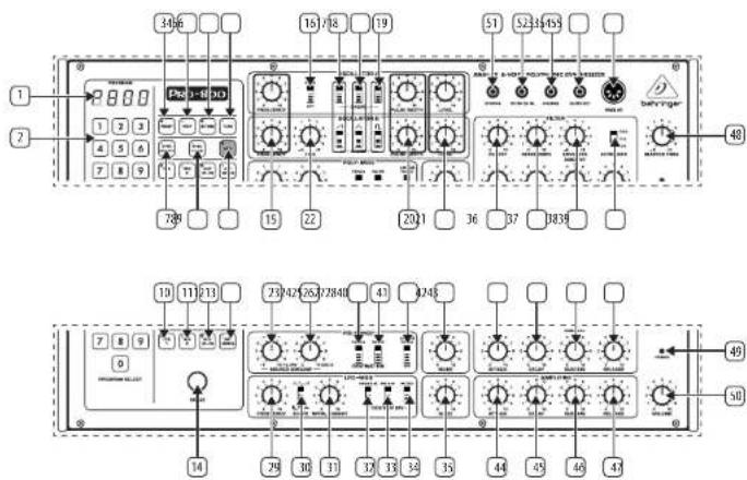
Top Panel
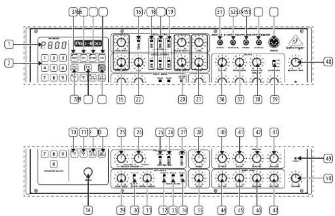
1 PROGRAM DISPLAY – indicates current program in Preset or Manual Modes; and parameters when using the menus.
2 PROGRAM SELECT 0-9 switches. used to select program numbers 0-100. There are four banks of programs, making 400 programs overall. These buttons are also used to access menu functions as described below.
3 PRESET - when active, shows the PRO-800 is programmed according to memory. When unlit indicates manual mode, when blinking indicates that a parameter has been edited but not stored.
4 PERF - switches the PRO-800 to manual mode. Front panel controls will be active. First press accesses patch parameters, second accesses manual mode (display shows P800).
5 SETTINGS – enter the settings menu.
6 TUNE - activates tuning of oscillators and filters.
SYNC SOURCE – choose from internal, MIDI, USB or Sync In.
SYNC CLOCK - First press sets clock BPM. Second press: clock subdivision (34, 1% etc)
Third press: clock in PPQN settings: 24, 48, 96, 192 are available.
? REC – used for storing programs or sequences. Also used to latch the arpeggiator.
10 SEQ 1 – selects sequence bank 1 for recording or playback.
11 SEQ 2 – selects sequence bank 2 for recording or playback.
12 ARP UP DN – controls arpeggiator by key position. See Arpeggiator below.
13 ARP ASSIGN – controls arpeggiator by key order See Arpeggiator below.
14 VALUE – used to adjust parameter values such as tempo.
15 FREQUENCY – adjusts the over a 4 octave range for both oscillators. The frequency range can be set using the additional parameters menu (see below).
16 SYNC – forces OSC A to follow OSC B in hard synchronization.
17 SAWTOOTH – enables a full-level waveshape containing all harmonics.
18 TRIANGLE – enables a full-level triangle wave, containing little harmonic energy.
19 PULSE – enables a full-level waveshape depending on the setting of the pulse width control.
20 PULSE WIDTH – adjusts the harmonic content of the pulse wave by setting its cycle from around 1 to 99%. 50% is approximately a square wave.
21 LEVEL – determines the volume of the oscillator. Signal is clean up to S, then a distortion effect is gradually introduced.
[22] FINE – raises OSC B frequency up to one semitone for detuning effects.
23 FIL ENV - adjusts the level of the filter envelope generator source for the Polymod.
24 OSCB – adjusts the level of OSCB source for the Polymod.
25 FREQ A – selects OSC A frequency as a destination of the Polymod.
26 FILTER – selects filter cutoff frequency as a destination of the Polymod.
21 UNISON TRACK – with no keys pressed the current program will be switched to UNISON operation where all 8 voices are assigned to one note monophonically. With a chord held and unison then engaged, the chord will track up and down the keyboard. Pressing the button while holding a single note turns the Pro 800 into a monophonic synthesizer.
28 NOISE – increase the noise generator level.
LFO FREQUENCY – adjust the LFO speed from about 0.25 to 20 Hz.
SHAPE – LFO shape selection is made in the additional parameters menu and are assigned in pairs.
1. Tri-Pulse 2. Sine-Random 3.
Saw-Noise.
31 INITIAL AMOUNT – programs mod depth independently of an external MOD wheel.
32 FREQ A-B – applies LFO modulation to both oscillator frequencies.
33 PW A-B – applies LFO modulation to pulse width of both oscillators.
34 FILTER – applies LFO modulation to the filter cutoff frequency.
35 GLIDE – increases the portamento between notes.
16 CUTOFF – adjusts the cutoff frequency of the 24 dB/octave (4-pole) low-pass filter.
37 RESONANCE – adjusts the resonance of the filter. This emphasizes the frequencies around the cutoff point.
38 ENVELOPE AMOUNT – sets the depth of the applied envelope. If set to 0, the filter envelope will have no effect.
18 19 Quick Start GuidePRO 800
PRO-800 Controls
EN Step 2: Controls
35 KEYBOARD – when the FULL switch is selected CV is applied to the filters cutoff frequency with the filter tracking the keyboard. When in the OFF position notes played higher on the keyboard will have more of their overtones suppressed than notes played in the lower register. The VS setting gives an effect in between the FULL and OFF settings. Full setting allows a self-oscillating filter to accurately track the keyboard.
40 ATTACK – controls the attack time of the filter's envelope.
41 DECAY – controls the decay time of the filter's envelope.
42 SUSTAIN – controls the sustain level of the filter's envelope.
43 RELEASE – controls the release time of the filter's envelope.
44 ATTACK – controls the attack time of the amplifier's envelope.
45 DECAY – controls the decay time of the amplifier's envelope.
46 SUSTAIN – controls the sustain level of the amplifier's envelope.
47 RELEASE – controls the release time of the amplifier's envelope.
48 MASTER TUNE – adjust the overall tuning of the synth (+ - 1 semitone).
49 POWER LED – indicates power is on.
50 VOLUME – sets the master volume.
51 SYNC IN – allows sync connection to external sources.
52 FILTER CV IN – allows the filter cutoff to be controlled by external sources. (amount set in settings)
53 PHONES – headphone connection.
54 AUDIO OUT - 18 audio output.
SS MIDI IN – accepts incoming MIDI data from the selected midi channel.
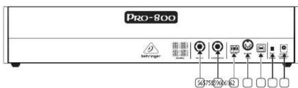
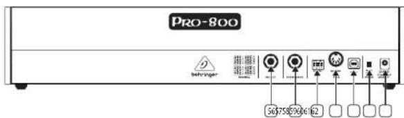
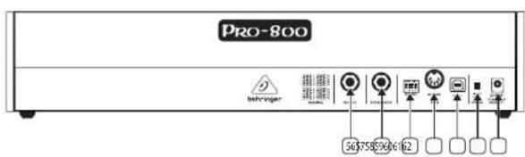
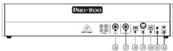
Rear Panel
56 OUTPUT – Connect to a mixer or audio interface 1/4" Jack cable.
57 FOOTSWITCH – connect a footswitch for sustain control.
58 MIDI CHANNEL SELECTION.
Move the four dip switches to select the MIDI channel.


59 MIDI OUT/THRU – MIDI OUT/THRU for outputting MIDI data.
60 USB PORT – Capable of sending and receiving MIDI information over USB. Also used for updates.
61 POWER SWITCH – Turns the synthesizer on and off.
62 POWER INPUT — Connect the supplied power supply only.
PRO-800 Getting started
EN Step 3: Getting started
OVERVIEW
This 'getting started' guide will help you set up the PRO-800 and briefly introduce its capabilities.
CONNECTION
To connect the PRO-800 to your system, please consult the connection guide earlier in this document.
SOFTWARE SETUP
The PRO-800 is a USB Class Compliant MIDI device, and so no driver installation is required. The PRO-800 does not require any additional drivers to work with Windows and MacOS.
HARDWARE SETUP
Make all the connections in your system. Keep the PRO-800 power turned off when making any connections.
Ensure your sound system is turned down.
Turn on the PRO-800 before turning on any power amplifiers and turn it off last. This will help prevent any turn on or turn off "pops or thumps" in your speakers.
WARM UP TIME
We recommend leaving 15 minutes or more time for the PRO-800 to warm up before recording or live performance. (Longer if it has been brought in from the cold.) This will allow the precision analog circuits time to reach their normal operating temperature and tuned performance.
FIRMWARE UPDATE
Please check the behringer.com website regularly for any updates to the Behringer SYNTHTRIBE app.
The app looks for the latest firmware file which can then be downloaded and used to update the PRO-800.
20 21 Quick Start GuidePRO 800
WARM UP TUNE TIME
Upon first power-up, the PRO-800 tunes itself. The tune light illuminates, and the display indicates the oscillator or filter being tuned from A1 through A8, b1 through b8 and F1 through F8 for Oscillator A, B and the Filter respectively. The routine takes about 20 seconds to complete depending on the tuning of your instrument.
It is normal to have to retune the instrument during the first 30 minutes of operation as the electronics warm to a stable operating temperature. To tune, simply press the tuning button as required.
MANUAL/PRESET MODES
Pressing the PRESET button switches between manual mode, in which the synthesiser parameters sound parameters reflect the active sonic state of the instrument, and preset mode in which the sound is a stored patch.
You can edit a stored patch, manual patch or preset patch at any time by completing the following:
-
Press the RECORD button on the keypad. It will blink.
-
Press the two-digit location to which you want to save the patch.
The patch is saved. It will overwrite whatever sound patch was there before.
You can cancel a patch store any time while the RECORD button is blinking by pressing it before pressing another button.
Below is a table summarising the parameters and keypad buttons required to access the synthesiser additional parameters. To access these parameters, press PERF once.
To select a parameter, press the keypad number repeatedly to scroll through the options, name and value will be displayed. To edit it, used the VALUE control.
| Key | Parameter Choices |
| 1 LFO Shape | Pulse-Triangle / Random-Sine / Noise - Saw(see below) |
| LFO Target | A /A/B | |
| LFO Speed | Range Fast / Slow | |
| 2 Vibrato Speed | - | |
| Vibrato Amount | - | |
| 3 | Mod Wheel Amount | Min / Law / High / Full |
| Mod Wheel Target | LFO / Vibratio | |
| Modulation Delay | - | |
| 4 VCA Env Shape | Fast Exp / Fast Lin / Slow Exp/ Slow Lin | |
| VCF Env Shape | Fast Exp / Fast Lin / Slow Exp/ Slow Lin | |
| 5 | Pitchbend Target | Off / VCO / VCF / Volume |
| Pitchbend Range | 0-24 |
| 6 | OscA Freq Pot Mode | Free / Semitone / Octave(see below) |
| OscB Freq Pot Mode | Free / Semitone / Octave(see below) |
| Keyboard TrackingReference Note | C1, C2, C3, C4 |
| 7 | VCA Velocity Amount | - |
| VCF Velocity Amount | - |
| 8 | VCA AftertouchAmount | - |
| VCF AftertouchAmount | - |
| LFO AftertouchAmount | - |
| 9 | Unison / SpreadDetune | - |
| Voice Spread | On / Off |
| 0 | Glide Mode | Time / Speed |
LFO SHAPE
The PRO-800 supports six waveforms in addition to the standard Triangle and Square waves including Sine, (Saw) Ramp Up, Random, Noise. To select the desired waveform:
-
For Triangle, Sine or Saw:
-
If you are in preset mode, make sure Settings is lit, else press it to access the additional parameters menu.
-
Switch the LFO-MOD Shape button to Triangle.
-
Press the 1 button once and use the Value control to select the Triangle, Sine or Saw. The display indicates the current selection.
-
For Square, Random or Noise:
-
Enter Pref mode,
-
Switch the LFO-MOD Shape button to Square.
-
Press the 1 button once and use the Value control to select the Square, Random or Noise. The display indicates the current selection.
OSCILLATOR FREQUENCY CONTROL MODE
Oscillator A and B frequency ranges are now controllable in three modes: Octave (the default value), Chromatic and Free. The range remains the same, but it is now possible to sweep the frequency of the oscillators with a greater or smaller degree of fine control. To select the oscillator sweep mode, press button 8 twice on the additional parameters page and use the VALUE control to select it.
Access Global Settings by pressing SETTINGS once and use the keypad numbers to scroll through the options.
| Key | Parameter | Choices / (Comments) |
| 1 MIDI Rx Channel | Off / 1 – | 6 / All / Dipswitch |
| MIDI Tx Channel | Thru / 1 – 16 / All / Dipswitch |
| MIDI CC | Off / Tx / Rx | TxRx |
| MIDI PC | Off / Tx / Rx / TxRx |
| Sync In Forward | On / Off |
| Sync In Polarity | Rise / Fall |
| Sync In Start/Stop | On / Off |
| Sync In PPQN | 1 PPS / 2 PPQ / 4 PPQ / 24 / 48 |
| Local | On / Off |
| Soft Thru | On / Off |
| 2 Transpose | - | |
| 3 | Preset Dump | (Second press to confirm SysEx dump) |
| 4 Voice Select 1 – 8 | |
| Voice Kill | On / Kill | |
| 5 | Retune Element | Osc A / Osc B / VCF |
| Octave | All / Oct 0–7 |
| 6 | Retune Encoder | Second press to initiate |
| 7 | Screen Brightness | - |
| Display Parameter Time | - |
| Preset Name Display | |
| 8 | Autotune Precision 0.5 | c / 1.0 c / 1.5 c / 2.0 c |
| 9 | External Filter Mod | - |
| Voice Priority Last / Low | / High |
| 0 | Factory Reset | (second press confirms restoration of factory settings) |
Holding the SETTINGS button and pressing the TUNE button lets you tune the last note played.
This will be saved in the preset data.
PRESET PARAMETERS
To access the PRESET parameters hold the PRESET button and use the keypad buttons to select the parameter required.
| Key | Parameter | Comments |
| 1 Bank A | - | |
| 2 Bank B | - | |
| 3 | Bank C | - |
| 4 Bank D | - | |
| 5 | Preset Copy | (copies the current preset values) |
| 6 | Preset Paste | (pastes the copied preset to a new location. Second press confirms) |
| 7 | Randomise Preset | - |
| 8 | Bank Copy First press copies current bank. Then navigate to another bank and use 9 |
| 9 | Bank Paste | Hold PRESET and press twice to paste the copied bank to its new location |
| 0 | Reset to basic patch | |
AUTOTUNE
The TUNE button starts the auto-calibration of the oscillators and filters, muting the output during the process. A short press will reset all tuning data and fully calibrate the device. A long press will start a faster recalibration of the tuning, adjusting to temperature changes of the analog circuits.
CHORD MODE
Holding a chord and switching the UNISON TRACK on stores that chord an allows it to be transposed across the keyboard. The chord will be saved as part of the preset. This can also be set by pressing the sustain pedal while holding a chord in UNISON mode.
TRANSPOSITION
By holding the PERF and SETTINGS buttons then playing a note on an attached MIDI keyboard the keyboard will transpose to the note played relative to C.
KEYBOARD MODES
The PRO-800 can be either in Polyphonic, Unison or Chord mode.
- The synthesizer starts in Polyphonic mode, in which any new note will be assigned to one of the 8 voices.
- If you switch Unison Track on with no pressed key, you are in Unison mode, all 8 voices will play the same note.
- If you switch Unison Track on with one or more pressed keys, you are in Chord mode. The pattern those keys made will now be transposed over the whole keyboard range by new notes.
- If you switch on Unison Track with one key pressed you enter single voice unison mode.
22 23 Quick Start GuidePRO 600
The foot switch input can be used to latch a new pattern of notes. New notes will be assigned to voices using one of those priority rules:
-
Last: New notes will always play; the oldest notes may be stolen.
-
Low: Only the lowest notes will play. In Unison or Chord mode, legato will be active.
-
High: Only the highest notes will play. In Unison or Chord mode, legato will be active.
The assignment priority is set in the additional parameters menu.
ARPEGGIATOR
The arpeggiator has two buttons to set its parameters. To set the arpeggio type hold the ARP UP-DN button and use the keypad to select:
1 - Arpegio Up
2 - Arpeggio Down
3 - Arpeggle Up and Down
4 - Arpeggie Up then Down
To assign the arpeggiator hold the ARP ASSIGN button and use the keypad to select:
1 - Played order
2 - Random order
Holding ARP button and pressing REC holds the current notes played. The foot switch input can also be used to hold the arpeggiator.
Holding a note or chord then pressing the ARP UP-DN button holds the note/chord in a drone without arpeggiation.
SEQ RECORDING
- Switch RECORD on.
- Press either SEQ 1 or SEQ 2.
- Start playing. (Recording does not begin until the first
key is pressed.
- When finished, press the footswitch or RECORD at the end point you want.
- The sequence will play continuously loop until the
appropriate SEQ switch is switched off.
- Care must be taken to not exceed the note limit, which is approximately 400, but may be less if the specific sequence contains long rests. If the note limit is exceeded, the sequence will only contain the last 400 notes—the earliest notes will be last.
- When both banks are being used, care must also be taken to not exceed the 400-note limit. The sequencer assigns memory priority to the bank which is currently being recorded, and will "steal" notes from the other bank once the 400 total note limit is reached. For example, if SEQ 1 already has a 250-note sequence recorded in it, you will erase SEQ 1 if you attempt to record more than about 150 notes in SEQ 2.
SEQ PLAYBACK
- To playback a sequence, press SEQ 1 or SEQ 2.
- The playback speed can be varied from 1/4 to 4X real-time. The SPEED control position for 1:1 playback speed is to the left of centre. This provides more control range of higher speeds.
- The playback speed can also be programmed. As the sequencer is playing back, set SPEED as desired, then press the RECORD switch (which will not light). Now whenever the sequence is selected it will play at this speed. The programmed speed can be edited and re-recorded (just like the synthesizer controls).
To stop, press the appropriate SEQ switch or the footswitch
POWER UP
Pressing the PRESET button while powering up the PRO-800 loads a generic preset, which can then be edited. Holding the SETTINGS button while powering up resets all settings to factory default. Holding the 0 key on the keypad while powering up performs a button test.
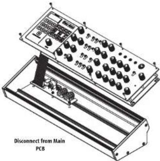
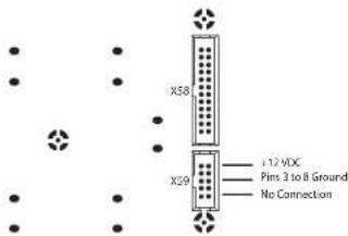
Eurorack Installation
The PRO-800 can be taken out of its factory chassis and fitted into a standard Eurorack case (not supplied).
We recommend that this procedure is carried out only by an experienced service technician to prevent personal injury or damage to the PRO-800. The Eurorack case will need to have a suitable power supply with enough capacity to power the PRO-800. Consumption is 1.2 A at 12 v DC.
A 10 pin to 16 pin adapter ribbon cable is supplied with the PRO-800.
Please ensure that the Eurorack case will supply +/- 12v DC and ground to the correct pins, and that the cable is at the correct orientation before proceeding.
Procedure
Please follow all steps in the correct order.
1. Disconnect the power and all other connections to the PRO-800.
2. Undo the eight screws on the top panel as shown. There is no need to undo any other screw.
3. Carefully lift the top panel assembly, and turn it over so that the PCB is facing upwards. Be careful not to pull the ribbon cable from the lower side of the main PCB.
4. Disconnect the 24 pin ribbon cable from the main PCB of the PRO-800 and remove the assembly from the chassis.

- Store the chassis assembly and power supply in a safe, dry place.
- Securely connect the 10 pin end of the supplied ribbon cable adapter to the main PCB of the PRO-800.
- Having ensured that your Eurorack case is isolated from the mains connect the 16 pin end of the ribbon cable to a spare outlet in the case.
- Secure the PRO-800 to the case using the eight panel screws.
- Perform a full safety test before using the PRO-800.
PRO-800 Controles

Paso 2: Controles
Panel superior
Panel trasero

Paso 2: Controles
Panel superior
PRO-800 Réglages
PRO-800 Bedienelemente
Eurorack Installation

56 57Quick Start GuidePRO 800
PRO-800 Controlli
Passo 2: Controlli
Pannello superiore

Pannello posteriore
64 65 Quick Star Guide PRO 800
PRO-800 Bediening
KL Stap 2: Bediening
Bovenpaneel

Achterpaneel

NL Stap 2: Bediening
Bovenpaneel
KL Stap 2: Bediening
72 73 Quick Start GuidePRO 800
PRO-800 Kontroller
SE Steg 2: Kontroller
Övre panel
Bakre panel

SE Steg 2: Kontroller
Övre panel
1 - Played order
2 - Random order
Eurorack Installation
80 81 Quick Start GuidePRO 500
PRO-800 Sterowanica
背面パネル
IP ステップ 2: コントロール
トップパネル
プロシージャ
98 99 Quick Start GuidePRO 800
PRO-800 控制
CH 第二步: 控制
顶面板

后面板

^① 第二步: 控制
顶面板
106 107 Quick Start GuidePRO 800
MIDI Continuous Controllers
EN The Pro 800 responds to a number of MIDI CC Controls:
ES El Pro 800 responde a una serie de controles CC (controladores continuos) MIDI:
FR Le Pro 800 peut réagir à diverses commandes MIDI CC:
Der Pro 800 reagiert auf eine Reihe von MIDI CC-Meldungen:
PT O Pro 800 é ativado pelo número dos controles CC do MIDI:
Il Pro 800 risponde a una serie di messaggi CC MIDI:
HL De Pro 800 reageert op een aantal MIDI-CC-controllers:
SE Pro 800 reagerar på ett antal MIDI CC-styrmeddelanden:
PL Pro 800 reaguje na różne funkcje MIDI CC:
JP Pro 800 は MIDI CC コントロール番号に応答します:
Pro 800 可响应许多 MIDI CC 控制:
| CC Num | Hex | Continuous - Coarse | Continuous - Fine tune | Steppedparams | MIDI standard |
| 0 0 --- Rank sel | | | | | |
| 1 1 --- Mod Wheel | | | | | |
| 2 | 2 --- Breath | | | | |
| 3 3 --- Master Tune | | | | | |
| 6 | 6 --- NRPN Data MSB | | | | |
| 7 | 7 --- Main volume | | | | |
| 8 | 8 OSC A Freq | --- | | | |
| 9 | 9 OSC A Vol | --- | | | |
| 10 | A OSC A PW | --- | | | |
| 11 | B OSC B Freq | --- | | | |
| 12 | C | OSC B Vol | - | - | - |
| 13 | D OSC B PW | --- | | | |
| 14 | E | OSC B Fine | --- | | |
| 15 | F | VCF Freq | --- | | |
| 16 | 10 | VCF Reso | - | - | - |
| 17 | 11 | VCF ENV amount | - | - | - |
| 18 | 12 | VCF Rel | - | - | - |
| 19 | 13 | VCF Sus | - | - | - |
| 20 | 14 | VCF Dec | - | - | - |
| 21 | 15 | VCF Atck | - | - | - |
| 22 | 16 | VCA Rel | - | - | - |
| 23 | 17 | VCA Sus | - | - | - |
| 24 | 18 | VCA Dec | - | - | - |
| 25 | 19 | VCA Atck | - | - | - |
| 26 | 1A | Pmod Filter Env amount | - | - | - |
| 27 | 1B | Pmod OSC B amount | - | - | - |
| 28 | 1C | LFO Freq | - | - | - |
| 29 | 1D | LFO Amount | - | - | - |
| 30 | 1E | Glide | - | - | - |
| 31 | 1F | VCA Vel | - | - | - |
| 32 | 20 | VCF Vel | - | - | - |
| 33 | 21 | Mod delay | - | - | - |
| 34 | 22 | Vib Freq | - | - | - |
| 35 | 23 | Vib Arnt | - | - | - |
| 36 | 24 | Unison Detune | - | - | - |
| 37 | 25 | Noise | - | - | - |
| 38 | 26 | --- NRPN Data LSB | | | |
| 39 | 27 | VCA Aftertouch | - | - | - |
| 40 | 28 | VCF Aftertouch | - | - | - |
| 41 | 29 | LFO Aftertouch amount | - | - | - |
| 42 | 24 | Pitch Range | - | - | - |
| 48 | 30 | - | - | OSC A Saw | - |
| 49 | 31 | - | - | OSC A Saw | - |
| 50 | 32 | - | - | OSC A Square | - |
| 51 | 33 | - | - | OSC B Saw | - |
108 109 Quick Start GuidePRO 800
| CC Num | Hex | Continuous - Coarse | Continuous - Fine tune | Stepped params | MIDI standard |
| 52 34 -- OSB B Tri- | | | | | |
| 53 35 -- OSB B Square- | | | | | |
| 54 36 -- OSC B Sync- | | | | | |
| 55 37 -- Fmod Freq A- | | | | | |
| 56 38 -- Fmod VCF | - | | | | |
| 57 39 -- LFO Shape | - | | | | |
| 58 3A -- LFO Speed | - | | | | |
| 59 | 3B | - | - | LFO Targets | - |
| 60 3C -- VCF Keyboard | - | | | | |
| 61 3D -- VCF ENV Exp | - | | | | |
| 62 3E -- VCF ENV Speed | - | | | | |
| 63 3F | -- VCA ENV Exp- | | | | |
| 64 40 -- Sustain pedal | | | | | |
| 65 41 -- Unison | - | | | | |
| 66 42 -- Bender target | - | | | | |
| 67 43 -- Modwheel Amount | - | | | | |
| 68 44 -- Chromatic Pitch A | - | | | | |
| 69 45 -- Chromatic Pitch B | - | | | | |
| 70 | 46 | - | - | Modwheel Target | - |
| 72 48 -- VCA ENV Speed | - | | | | |
| 73 49 -- Arp Mode | - | | | | |
| 74 4A -- LFO Dest Freq | - | | | | |
| 75 4B -- LFO Dest Filter | - | | | | |
| 76 4C -- LFO Dest PWM | - | | | | |
| 77 | 4D | - | - | Voice Spread | - |
| 78 | 4E | - | - | Keyboard Tracking | - |
| 79 AF -- Glide Mode- | | | | | |
| 80 50 - OSC A Freq | -- | | | | |
| 81 | 51 | - | OSC A Vol | - | - |
| 82 52 - OSC A PW | -- | | | | |
| 83 53 - OSC B Freq | -- | | | | |
| 84 | 54 | - | OSC B Vol | - | - |
| 85 55 - OSC B PW | -- | | | | |
| 86 56 - OSC B Fine | -- | | | | |
| 87 57 - VCF Freq | -- | | | | |
| 88 58 - VCF Reso | -- | | | | |
| 89 59 - VCF ENV amount | -- | | | | |
| 90 5A - VCF Rel | -- | | | | |
| 91 5B - VCF Sus | -- | | | | |
| 92 5C - VCF Dec | -- | | | | |
| 93 5D - VCF Atck | -- | | | | |
| 94 5E - VCA Rel | -- | | | | |
| 95 SF | -- VCA Sus | -- | | | |
| CC Num | Hex | Continuous - Coarse | Continuous - Fine tune | Stepped params | MIDI standard |
| 96 60 --- NRPN Data increment | | | |
| 97 61 --- NRPN Data decrement | | | |
| 98 62 --- NRPN Param LSB | | | |
| 99 63 --- NRPN Param MSB | | | |
| 100 | 64 - VCA Dec | -- | | | |
| 101 | 65 - VCA Atck | -- | | | |
| 102 | 66 - Pmod Filter Env amount | -- | | | |
| 103 | 67 - Pmod OSC B amount | -- | | | |
| 104 | 68 - LFO Freq -- | | | | |
| 105 | 69 - LFO Amount | -- | | | |
| 106 | 6A - Glide | -- | | | |
| 107 | 6B | - | VCA Vel | - | - |
| 108 | 6C | - | VCF Vel | - | - |
| 109 | 6D - Mod delay | -- | | | |
| 110 | 6E - Vib Freq | -- | | | |
| 111 | 6F | - | Vib Amt | - | - |
| 112 | 70 - Unison Detune | -- | | | |
| 113 | 71 - Noise | -- | | | |
| 114 | 72 - VCA Aftertouch | -- | | | |
| 115 | 73 - VCF Aftertouch | -- | | | |
| 116 | 74 - LFO Aftertouch | -- | | | |
| 117 | 75 | - | Pitch Range | - | - |
| 120 | 78 --- All sounds off | | | |
| 123 | 78 --- All notes off | | | |
110 111 Quick Start GuidePRO 800
Specifications
| Synthesizer Architecture |
| Number of voices 8 | |
| Type of oscillators 2 x 3340 per voice | |
| Type Analog | |
| Oscillators 16 (32.70 Hz to 8372.02 Hz across 4 ranges) |
| LFO 1 (0.08 Hz to 20 Hz) | |
| VCF 1 x 4-pole low pass (24 dB/oct. slope) | |
| Envelopes VCF, VCA | |
| Connectivity |
| Output 1⁄4" TS, unbalanced, max. +5.0 dBu | |
| Audio out 1⁄4" TS, unbalanced, max. +20.0 dBu | |
| Footswitch 1⁄4" TS, unbalanced | |
| Headphones 1⁄4" TRS, unbalanced, max. 7.5 mW @ 32 Ohm |
| Headphones output impedance 8 O | |
| MIDI In Out/Thru | 2 x 5-pin DIN/ 16 channels |
| USB (MIDI); USB 2.0, type B | |
| Sync in TS 3.5 mm 1PPS, 2PPO, 24PPO, 48PPO | |
| Filter CV IN TS 3.5 mm 0 V to +10 V | |
| USB |
| Type Class compliant USB 2.0, type B | |
| Supported operating systems | Windows 7 or higher/ Mac OS X 10.11.6 or higher |
| Program Section |
| Display | 4 number, 8-segment display |
| Buttons | 0 - 9 program select |
| Preset, perf. settings, tune |
| Sync source, sync clock, rec |
| SEQ 1, SEQ 2, ARP UP-ON, Arp Assign. |
| Control | Value encoder |
| Oscillator Section |
| Controls | Frequency (OSC A & B): -5 to +5 |
| Level (OSC A & B) 0 to 10 |
| Pulse Width (OSC A & B) 0 to 10 |
| Fine (OSC B only) |
| Switches | Shape (OSC A & B): Sawtooth, Triangular and Pulse |
| OSC A sync on/off |
| POLY-MOD Section |
| Controls | FILEW 0 to 10 |
| OSC B S 0 to 10 |
| Switches | Freq A destination |
| Filter destination |
| Noise Section |
| Control | Noise level 0 to 10 |
| LFO-MOD Section |
| Controls | Frequency 0 to 10 |
| Initial amount 0 to 10 |
| Switches | Shape: Triangle or Pulse |
| Freq A-B |
| PW A-B |
| Filter |
| Glide Section |
| Controls | Rate: 0 to 10 |
| Filter Section |
| Controls | Cutoff frequency: 0 to 10 |
| Resonance: 0 to 10 |
| Envelope amount: 0 to 10 |
| Attack: 0 to 10 |
| Decay: 0 to 10 |
| Sustain: 0 to 10 |
| Release: 0 to 10 |
| Switch | KYBD amount: off, 3⁄4, FULL |
112 113 Quick Start GuidePRO 800
EN Specifications
| Amplifier Section |
| Controls | Attack: 0 to 10 |
| Decay: 0 to 10 |
| Sustain: 0 to 10 |
| Release: 0 to 10 |
| Output Section |
| Controls | Volume: 0 to 10 |
| Master tune -5 to +5 |
| LED Power | |
| Power Requirements |
| External power adaptor 12 V DC 1200 mA | |
| Power consumption 14.4 W maximum | |
| Environmental |
| Operating temperature range 5°C to 45°C (41°F to 113°F) |
| Physical |
| Dimensions (H x W x D) 96.6 x 424.4 x 135.6 mm (3.8 x 16.7 x 5.3") |
| Weight 1645 g (3.63 lb) | |
| Eurorack HP 80 hp | |
技术参数

Important information As

portantes

Informations importantes
1. Register online.
Please register your new Music Tribe equipment right after you purchase it by visiting musictribe.com. Registering your purchase using our simple online form helps us to process your repair claims more quickly and efficiently. Also, read the terms and conditions of our warranty, if applicable.
- Malfunction. Should your Music Tribe Authorized Reseller not be located in your vicinity, you may contact the Music Tribe Authorized Fulfiller for your country listed under "Support" at musictribe.com. Should your country not be listed, please check if your problem can be dealt with by our "Online Support" which may also be found under "Support" at musictribe.com. Alternatively, please submit an online warranty claim at musictribe.com BEFORE returning the product.
3. Power Connections.
Before plugging the unit into a power socket, please make sure you are using the correct mains voltage for your particular model. Faulty fuses must be replaced with fuses of the same type and rating without exception.
1. Registro online.

Responsible Party Name: Music Tribe Commercial NV Inc.
Address: 122 E. 42nd St.1,
8th Floor NY, NY 10168,
United States
Email Address: legal@musictribe.com
PRO-800
This equipment has been tested and found to comply with the limits for a Class B digital device, pursuant to part 15 of the FCC Rules. These limits are designed to provide reasonable protection against harmful interference in a residential installation. This equipment generates, uses and can radiate radio frequency energy and, if not installed and used in accordance with the instructions, may cause harmful interference to radio communications. However, there is no guarantee that interference will not occur in a particular installation. If this equipment does cause harmful interference to radio or television reception, which can be determined by turning the equipment off and on, the user is encouraged to try to correct the interference by one or more of the following measures:
- Reorient or relocate the receiving antenna.
- Increase the separation between the equipment and receiver.
- Connect the equipment into an outlet on a circuit different from that to which the receiver is connected.
- Consult the dealer or an experienced radio/TV technician for help.
This equipment complies with Part 15 of the FCC rules. Operation is subject to the following two conditions:
(1) this device may not cause harmful interference, and (2) this device must accept any interference received, including interference that may cause undesired operation.
Changes or modifications to the equipment not expressly approved by Music Tribe can void the user's authority to use the equipment.
CE
Hereby, Music Tribe declares that this product is in compliance with Directive 2014/35/EU, Directive 2014/30/EU, Directive 2011/65/EU and Amendment 2015/863/EU, Directive 2012/19/EU,
Regulation 519/2012 REACH SVHC and Directive 1907/2006/EC.
Full text of EU DoC is available at
https://community.musictribe.com/
EU Representative: Music Tribe Brands DK A/S
Address: Gammel Strand 44, DK-1202 København K, Denmark
UK Representative: Music Tribe Brands UK Ltd.
Address: 8th Floor, 20 Farringdon Street London EC4A 4AB,
United Kingdom

Correct disposal of this product: This symbol indicates that this product must not be disposed of with household waste, according to the WEEE Directive (2012/19/EU) and your national law. This product should be taken to a collection center licensed for the recycling of waste electrical and electronic equipment (EEE). The mishandling of
this type of waste could have a possible negative impact on the environment and human health due to potentially hazardous substances that are generally associated with EEE. At the same time, your cooperation in the correct disposal of this product will contribute to the efficient use of natural resources. For more information about where you can take your waste equipment for recycling, please contact your local city office, or your household waste collection service.
We Hear You