AOBD2 - Measuring equipment Perel - Free user manual and instructions
Find the device manual for free AOBD2 Perel in PDF.
| Product Type | OBD2, EOBD and JOBD diagnostic tool |
| Brand | Perel |
| Model | AOBD2 |
| Dimensions | 126 x 78 x 28 mm |
| Weight | 200 g |
| Power supply | 8 V to 16 V (via vehicle battery) |
| Display | Backlit LCD, 2 lines, 8 characters |
| Main functions | Read and clear DTC error codes, read VIN number, I/M readiness status, rescan, language selection |
| Compatible protocols | CAN, VPW, PWM, ISO9141, KWP2000 |
| Compatible vehicles | All vehicles compliant with OBD2/EOBD/JOBD with 16-pin connector (EU/Asia from 2000, USA from 1996) |
| Operating temperature | 0 °C to 50 °C (32 °F to 122 °F) |
| Storage temperature | -20 °C to 70 °C (-4 °F to 158 °F) |
| Maintenance and cleaning | Keep dry, clean, free of oil/water/grease. Use a mild detergent on a clean cloth. |
| Safety | Do not open the housing, do not connect/disconnect while powered, use in a ventilated area, wear eye protection, block the drive wheels. |
| Spare parts and repairability | No user-serviceable parts. Contact the dealer for replacement parts. |
| Warranty | 2 years for EU consumers (Velleman conditions) |
| General information | Manual available in multiple languages. Intended use: automotive diagnostics. |
Frequently Asked Questions - AOBD2 Perel
User questions about AOBD2 Perel
0 question about this device. Answer the ones you know or ask your own.
Ask a new question about this device
Download the instructions for your Measuring equipment in PDF format for free! Find your manual AOBD2 - Perel and take your electronic device back in hand. On this page are published all the documents necessary for the use of your device. AOBD2 by Perel.
USER MANUAL AOBD2 Perel
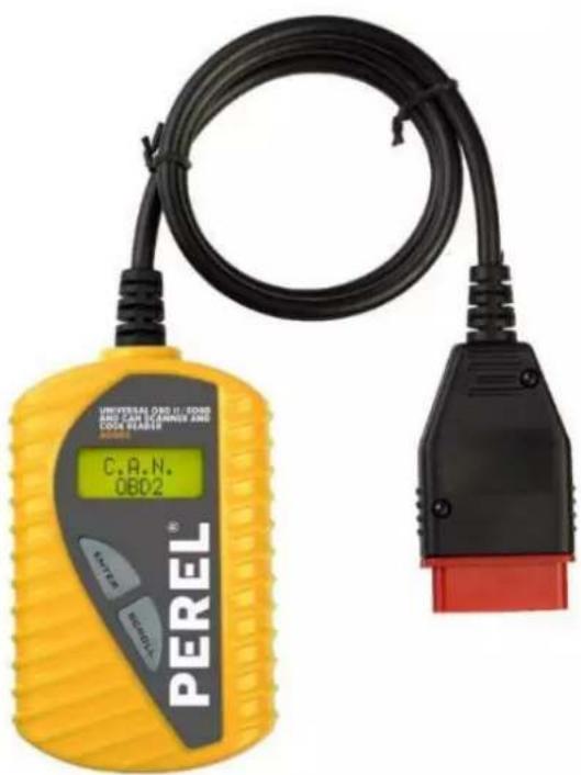
UNIVERSAL OBD-II/EOBD CODE READER
UNIVERSELE OBD-II/EOBD FOUTCODELEZER
LECTEUR DE CODES DÉFAUTS OBD-II/EOBD UNIVERSEL
LECTOR DE CÓDIGOS UNIVERSAL OBD-II/EOBD Y CAN
OBD-II/EOBD UND CAN UNIVERSAL-DIAGNOSEGERÄT
UNIWERSALNY SKANER I CZYTNIK KODÓW OBD-II/EOBD I CAN
SCANNER E LEITOR DE CÓDIGO UNIVERSAL OBD-II/EOBD E CAN
text_image
UNIVERSAL OBD IT. EODR AND CAN COMPRET AND COOK BEASER C.R.N. OBD2 PEREL®USER MANUAL 2
HANDLEIDING 9
MODE D'EMPLOI 16
MANUAL DEL USUARIO 23
To all residents of the European Union
Important environmental information about this product
This symbol on the device or the package indicates that disposal of the device after its lifecycle could harm the environment. Do not dispose of the unit (or batteries) as unsorted municipal waste; it should be taken to a specialized company for recycling. This device should be returned to your distributor or to a local recycling service. Respect the local environmental rules.

If in doubt, contact your local waste disposal authorities.
Thank you for choosing Perel! Please read the manual thoroughly before bringing this device into service. If the device was damaged in transit, do not install or use it and contact your dealer.
2. Safety Instructions

- This device can be used by children aged from 8 years and above, and persons with reduced physical, sensory or mental capabilities or lack of experience and knowledge if they have been given supervision or instruction concerning the use of the device in a safe way and understand the hazards involved. Children shall not play with the device. Cleaning and user maintenance shall not be made by children without supervision.
-
Do not disassemble or open the cover. There are no user-serviceable parts inside the device. Refer to an authorized dealer for service and/or spare parts.
-
Always perform automotive testing in a safe environment. Operate in a well-ventilated work area – exhaust gases are poisonous!
- Wear eye protection. Keep clothing, hair, tools, test equipment, etc. away from all moving or hot engine parts.
- Put blocks on drive wheels and never leave the vehicle unattended while running tests.
- Use extreme caution when working around the ignition coil, distributor cap, ignition wires and spark plugs. These components create hazardous voltages when the engine is running.
- Put the transmission in PARK (for automatic transmission) or NEUTRAL (for manual transmission). Make sure the parking brake is engaged.
- Keep a fire extinguisher suitable for gasoline/chemical/electrical fires nearby.
- Do not connect or disconnect any test equipment with the ignition on or when the engine is running.
- Keep the code reader dry, clean and free from oil, water and grease. Use a mild detergent on a clean cloth to clean the outside of the code reader when necessary.
3. General Guidelines
Refer to the Velleman® Service and Quality Warranty on the last pages of this manual.

- Protect this device from shocks and abuse. Avoid brute force when operating the device.
- Familiarise yourself with the functions of the device before actually using it.
- All modifications of the device are forbidden for safety reasons. Damage caused by user modifications to the device is not covered by the warranty.
- Only use the device for its intended purpose. All other uses may lead to short circuits, burns, electroshocks, crash, etc. Using the device in an unauthorized way will void the warranty.
- Damage caused by disregard of certain guidelines in this manual is not covered by the warranty and the dealer will not accept responsibility for any ensuing defects or problems.
- Nor Velleman nv nor its dealers can be held responsible for any damage (extraordinary, incidental or indirect) – of any nature (financial, physical...) arising from the possession, use or failure of this product.
- Do not switch the device on immediately after it has been exposed to changes in temperature. Protect the device against damage by leaving it switched off until it has reached room temperature.
- Keep this manual for future reference.
4. Product Features and Vehicle Coverage
- multi-language auto diagnostic tool for OBD-II, EOBD and JOBD
- reads and erases DTCs
• supports CAN (Controller Area Network), VPW, PWM, ISO9141, KWP2000 protocols
• retrieves VIN (Vehicle Identification No.) on 2002 and newer vehicles supported by mode 9
• works with all OBD-II, EOBD, JOBD compliant vehicles with a 16-pin interface
o for EU and Asia: all 2000 and newer cars
o for US: all 1996 and newer cars, light trucks and SUV's
o all CAN, VPW, PWM, ISO9141, KWP2000 protocols compliant vehicles (including those equipped with the next-generation protocol Control Area Network)
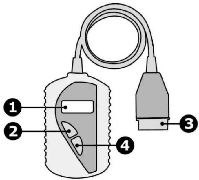
5. Overview
text_image
Diagram of a medical or diagnostic device with labeled parts including a test tube, connector, and cable.| 1 | LCD display |
| 2 | ENTER button |
| 3 | OBD-II connector |
| 4 | SCROLL button |
6. Operation
6.1 Reading Codes

WARNING
Do not connect or disconnect any test equipment with the ignition on or when the engine is running.

- Turn off the ignition of the car.
- Locate the 16-pin Data Link Connector (DLC). Plug the code reader into the DLC.
- Wait for the code to initialize.
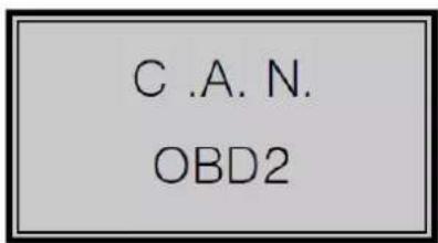
text_image
C .A. N. OBD2AOBD2
- Turn on the ignition but do not start the car.
- Press ENTER. A sequence of messages showing the OBD protocols may be observed on the display until the vehicle protocol is detected.
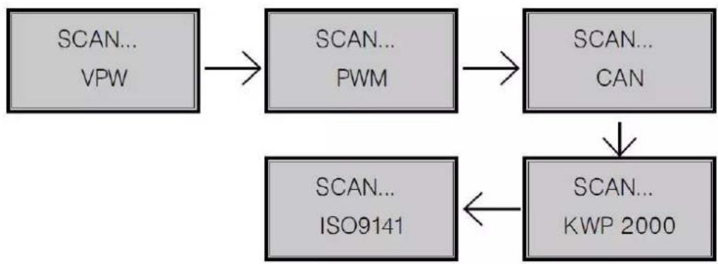
flowchart
graph TD
    A["SCAN... VPW"] --> B["SCAN... PWM"]
    B --> C["SCAN... CAN"]
    C --> D["SCAN... KWP 2000"]
    D --> E["SCAN... ISO9141"]
Note that not all the above messages will necessarily be observed.
If a LINK ERROR message is displayed, turn off the ignition for about 10 seconds, check if the code reader is securely connected and turn the ignition back on. Repeat from step 5.
If the error message reappears, check if the vehicle is compatible with the code reader.
- Wait for the main menu to be displayed. Select DTC by pressing ENTER.
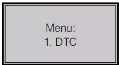
text_image
Menu: 1. DTCIf there are no Diagnostic Trouble Codes (DTCs) retrieved the display will indicate NO CODES.

text_image
NO CODESIf there are any DTCs, the total number of the Fault Codes followed by that of the Pending Codes will be displayed.
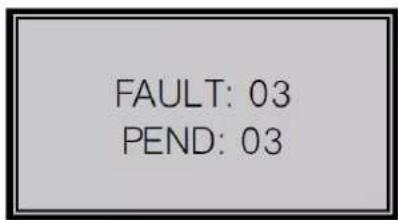
text_image
FAULT: 03 PEND: 03- Read the DTCs by pressing SCROLL. The first code number will be displayed on the first line, the numerical sequence of the code and the total number of the codes stored will be displayed on the second line. To view additional codes, press SCROLL until all codes have been displayed.
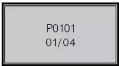
text_image
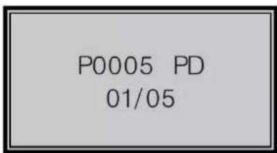
P0101 01/04If the code retrieved is a pending code, PD will be displayed.
text_image
P0005 PD 01/05To view previous codes, press SCROLL to scroll through the list until the first code is displayed.
- Refer to the list of DTCs on the last pages of this manual.
6.2 Erasing Codes
 | WARNING |  |
| Erasing the DTCs allows the code reader to delete not only the codes from the vehicle's on-board computer, but also manufacturer-specific data. Further, the I/M Readiness Status for all vehicle monitors is reset to Not Ready or Not Complete. Do not erase the codes before the system has been checked by a professional technician. |
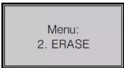
- If you decide to erase the DTCs, select ERASE and press ENTER.
text_image
Menu: 2. ERASEIf the code reader is not connected or no communication is established with the vehicle, then refer chapter 6.1 Reading Codes, steps 1 to 6.
- Press Yes to erase or No to cancel.

text_image
ERASE? YES NO- If the codes are successfully cleared, ERASE DONE will be displayed. Press ENTER to return to the main menu.
ERASE DONE!
If the codes are not successfully cleared, ERASE FAIL will be displayed. Press ENTER to return to the main menu.
ERASE FAIL!
The I/M Readiness function is used to check the operations of the emission system on OBD-II-compliant vehicles. It is an excellent function to use prior to having a vehicle inspected for compliance to a state emissions programme. A negative test result does not necessarily indicate that the tested vehicle will fail the state I/M inspection.
YES: All supported monitors on the vehicle have completed their diagnostic testing and the MIL light is on.
NO: At least one monitor supported on the vehicle has not completed its diagnostic testing and/or the MIL light is on.
READY: Indicates that a particular monitor being checked has completed its diagnostic testing.
NOT RDY: Indicates that a particular monitor being checked has not completed its diagnostic testing.
N/A: The monitor is not supported on that vehicle.
→: A flashing right arrow indicates additional information is available on the next screen.
←: A flashing left arrow indicates additional information is available on the previous screen.

- Select the I/M function by pressing ENTER.
Menu:
-
I/M
-
Use SCROLL to view the status of the MIL light and the monitors:
MISFIRE: Misfire monitor.
FUEL: Fuel system monitor.
CCM: Comprehensive components monitor.
EGR: EGR system monitor.
O2S: O2 sensors monitor.
AT: Catalyst monitor.
AOBD2
EVAP: Evaporative system monitor.
HO2S: O2 sensor heater monitor.
2AIR: Secondary air monitor.
HCM: Heated catalyst monitor.
A/C: A/C system monitor.
- Press ENTER to return to the main menu.
6.4 Viewing the Vehicle Identification Number (VIN)
- Select the VIN function by pressing ENTER.

text_image
Menu: 4. VIN- Use SCROLL to view the additional digits of the VIN.
- Press ENTER to return to the main menu.
6.5 Rescanning Data
| IMPORTANT |
| The RESCAN function allows you to retrieve the most current data stored in the ECM or to relink to the vehicle if communication is disconnected. |
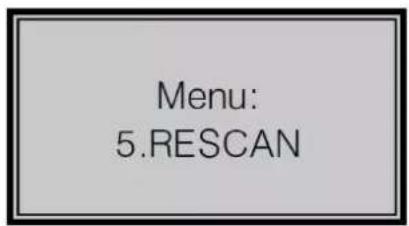
- Select the RESCAN function by pressing ENTER.
text_image
Menu: 5.RESCAN- Press ENTER to return to the main menu.
6.6 Language Selection
- Select the LANGUAGE function by pressing ENTER.

text_image
Menu: 6. LANGUAGE- Select your language by pressing SCROLL and confirm with ENTER.
- Press SCROLL to return to the main menu.
6.7 Diagnostic Trouble Codes (DTCs)

WARNING
Parts or components should not be replaced based on only a DTC check without consulting the vehicle service manual or a professional technician!

The DTC list on the final pages of this manual is a generic code list. Consult your vehicle service manual for more information.
7. Technical Specifications
display .... backlit 2-line LCD, 8 characters operating temperature .... 0 °C to 50 °C (32 °F to 122 °F) storage temperature .... -20 °C to 70 °C (-4 °F to 158 °F) power .... 8-16 V, provided via vehicle battery dimensions .... 126 x 78 x 28 mm weight.... 200 g
Use this device with original accessories only. Velleman nv cannot be held responsible in the event of damage or injury resulting from (incorrect) use of this device. For more info concerning this product and the latest version of this manual, please visit our website www.perel.eu. The information in this manual is subject to change without prior notice.
© COPYRIGHT NOTICE
The copyright to this manual is owned by Velleman nv. All worldwide rights reserved. No part of this manual may be copied, reproduced, translated or reduced to any electronic medium or otherwise without the prior written consent of the copyright holder.
HANDLEIDING
1. Inleiding
text_image
Diagram of a medical or diagnostic device with labeled parts including a test tube, connector, and cable.| 1 | lcd-display |
| 2 | ENTER-knop |
| 3 | OBDII-connector |
| 4 | SCROLL-knop |
6. Gebruik
6.1 Foutcodes lezen

WAARSCHUWING
MISFIRE: Misfire monitoring.
FUEL: Fuel system monitoring.
CCM: Comprehensive component monitoring.
EGR: EGR system monitoring.
O2S: O2 sensors Monitoring.
AT: Catalyst monitoring.
AOBD2
EVAP: Evaporative system monitoring.
HO2S: O2 sensor heater monitoring.
2AIR: Secondary air monitoring.
HCM: Heated catalyst monitoring.
A/C: A/C system monitoring.
text_image
Diagram of a medical or diagnostic device with labeled parts including a test tube, connector, and probe.text_image
Diagram of a medical or diagnostic device with labeled parts including a test tube, plug, and connector.text_image
Diagram of a medical or diagnostic device with labeled parts including a probe, cable, and connector.| 1 | LCD-Display |
| 2 | Taste ENTER |
| 3 | OBD-II- Diagnoseanschluss |
| 4 | Taste SCROLL |
6. Anwendung
text_image
Diagram of a medical or diagnostic device with labeled parts including a test tube, connector, and cable.text_image
Diagram of a medical or diagnostic device with labeled parts including a cable, connector, and terminal blocks.APPENDIX I Generic DTC Definitions
OBDII Generic DTC Definitions
| P0001 | Fuel Volume Regulator Control Circuit Open |
| P0002 | Fuel Volume Regulator Control Circuit Range/Performance |
| P0003 | Fuel Volume Regulator Control Circuit Low |
| P0004 | Fuel Volume Regulator Control Circuit High |
| P0005 | Fuel Shutoff Valve. A Control Circuit Open |
| P0006 | Fuel Shutoff Valve. A Control Circuit Low |
| P0007 | Fuel Shutoff Valve. A Control Circuit High |
| P0008 | Engine Position System Performance (Bank 1) |
| P0009 | Engine Position System Performance (Bank 2) |
| P0010 | Camshaft Position Actuator A -Bank 1 Circuit Malfunction |
| P0011 | Camshaft Position Actuator A -Bank 1 Timing Over-Advanced |
| P0012 | Camshaft Position Actuator A - Bank 1 Timing Over-Retarded |
| P0013 | Camshaft Position Actuator B - Bank 1 Circuit Malfunction |
| P0014 | Camshaft Position Actuator B - Bank 1 Timing Over-Advanced |
| P0015 | Camshaft Position Actuator B - Bank 1 Timing Over-Retarded |
| P0016 | Cam/Crankshaft Pos. Correlation Sensor A - Bank 1 |
| P0017 | Cam/Crankshaft Pos. Correlation Sensor B - Bank 1 |
| P0018 | Cam/Crankshaft Pos. Correlation Sensor A - Bank 2 |
| P0019 | Cam/Crankshaft Pos. Correlation Sensor B - Bank 2 |
| P0020 | Camshaft Position Actuator A - Bank 2 Circuit Malfunction |
| P0021 | Camshaft Position Actuator A - Bank 2 Timing Over-Advanced |
| P0022 | Camshaft Position Actuator A - Bank 2 Timing Over-Retarded |
| P0023 | Camshaft Position Actuator B - Bank 2 Circuit Malfunction |
| P0024 | Camshaft Position Actuator B - Bank 2 Timing Over-Advanced |
| P0025 | Camshaft Position Actuator B - Bank 2 Timing Over-Retarded |
| P0026 | Intake Valve-Bank 1 Control Solenoid CKT Range/Performance |
| P0027 | Exhaust Valve-Bank1 Control Solenoid CKT Range/Performance |
| P0028 | Intake Valve-Bank 2 Control Solenoid CKT Range/Performance |
| P0029 | Exhaust Valve-Bank2 Control Solenoid CKT Range/Performance |
| P0030 | HO2S Bank 1 Sensor 1 Heater Circuit |
| P0031 | HO2S Bank 1 Sensor 1 Heater Circuit Low |
| P0032 | HO2S Bank 1 Sensor 1 Heater Circuit High |
| P0033 | Turbo/Sup Wastegate Control Circuit |
| P0034 | Turbo/Sup Wastegate Control Circuit Low |
| P0035 | Turbo/Sup Wastegate Control Circuit High |
| P0036 | HO2S Bank 1 Sensor 2 Heater Circuit |
| P0037 | HO2S Bank 1 Sensor 2 Heater Circuit Low |
| P0038 | HO2S Bank 1 Sensor 2 Heater Circuit High |
| P0039 | Turbo/Super Charger Bypass Control CKT Performance |
| P0040 | O2 Bank 1 Sensor 1 Signals Swapped w/ O2 Bank 2 Sensor 1 |
| P0041 | O2 Bank 1 Sensor 2 Signals Swapped w/ O2 Bank 2 Sensor 2 |
| P0042 | HO2S Bank 1 Sensor 3 Heater Circuit |
| P0043 | HO2S Bank 1 Sensor 3 Heater Circuit Low |
| P0044 | HO2S Bank 1 Sensor 3 Heater Circuit High |
| P0045 | Turbo/Super Charger Boost Control Solenoid A Circuit Open |
| P0046 | Turbo/Super Charger Boost Control Solenoid A Circuit Range/ Perform |
| P0047 | Turbo/Super Charger Boost Control Solenoid A Circuit Low |
| P0048 | Turbo/Super Charger Boost Control Solenoid A Circuit High |
| P0049 | Turbo/Super Charger Boost Input/Turbine Speed Overspeed |
| P0050 | HO2S Bank 2 Sensor 1 Heater Circuit |
| P0051 | HO2S Bank 2 Sensor 1 Heater Circuit Low |
| P0052 | HO2S Bank 2 Sensor 1 Heater Circuit High |
| P0053 | HO2S Bank 1 Sensor 1 Heater Resistance |
| P0054 | HO2S Bank 1 Sensor 2 Heater Resistance |
| P0055 | HO2S Bank 1 Sensor 3 Heater Resistance |
| P0056 | HO2S Bank 2 Sensor 2 Heater Circuit |
| P0057 | HO2S Bank 2 Sensor 2 Heater Circuit Low |
| P0058 | HO2S Bank 2 Sensor 2 Heater Circuit High |
| P0059 | HO2S Bank 2 Sensor 1 Heater Resistance |
| P0060 | HO2S Bank 2 Sensor 2 Heater Resistance |
| P0061 | HO2S Bank 2 Sensor 3 Heater Resistance |
| P0062 | HO2S Bank 2 Sensor 3 Heater Circuit |
| P0063 | HO2S Bank 2 Sensor 3 Heater Circuit Low |
| P0064 | HO2S Bank 2 Sensor 3 Heater Circuit High |
| P0065 | Air Assisted Injector. Control Range/Performance |
| P0066 | Air Assisted Injector. Control Circuit Low |
| P0067 | Air Assisted Injector. Control Circuit High |
| P0068 | MAF/MAP Sensor Throttle Position Correlation |
| P0069 | MAP/BARO Correlation |
| P0070 | Ambient Air Temp. Sensor Circuit |
| P0071 | Ambient Air Temp. Sensor Range/Performance |
| P0072 | Ambient Air Temp. Sensor Circuit Low |
| P0073 | Ambient Air Temp. Sensor Circuit High |
| P0074 | Ambient Air Temp. Sensor CKT Intermittent |
| P0075 | Intake Valve-Bank 1 Control Circuit |
| P0076 | Intake Valve-Bank 1 Control Circuit Low |
| P0077 | Intake Valve-Bank 1 Control Circuit High |
| P0078 | Exhaust Valve-Bank1 Control Circuit |
| P0079 | Exhaust Valve-Bank1 Control Circuit Low |
| P0080 | Exhaust Valve-Bank1 Control Circuit High |
| P0081 | Intake Valve-Bank 2 Control Circuit |
| P0082 | Intake Valve-Bank 2 Control Circuit Low |
| P0083 | Intake Valve-Bank 2 Control Circuit High |
| P0084 | Exhaust Valve-Bank2 Control Circuit |
| P0085 | Exhaust Valve-Bank2 Control Circuit Low |
| P0086 | Exhaust Valve-Bank2 Control Circuit High |
| P0087 | Fuel Rail Pressure Too Low |
| P0088 | Fuel Rail Pressure Too High |
| P0089 | Fuel Pressure Regulator 1 Performance |
| P0090 | Fuel Pressure Regulator 1 Control Circuit |
| P0091 | Fuel Pressure Regulator 1 Control Circuit Low |
| P0092 | Fuel Pressure Regulator 1 Control Circuit High |
| P0093 | Fuel System Leak (Large) |
| P0094 | Fuel System Leak (Small) |
| P0095 | IAT Sensor 2 Circuit |
| P0096 | IAT Sensor 2 CKT Range/Performance |
| P0097 | IAT Sensor 2 Circuit Low |
| P0098 | IAT Sensor 2 Circuit High |
| P0099 | IAT Sensor 2 CKT Intermittent |
| P0100 | MAF or VAF A Circuit Malfunction |
| P0101 | MAF or VAF A Circuit Range/Performance |
| P0102 | MAF or VAF A Circuit Low Input |
| P0103 | MAF or VAF A Circuit High Input |
| P0104 | MAF or VAF A Circuit Intermittent |
| P0105 | MAP/BARO Circuit Malfunction |
| P0106 | MAP/BARO CKT Range/Performance |
| P0107 | MAP/BARO Circuit Low Input |
| P0108 | MAP/BARO Circuit High Input |
| P0109 | MAP/BARO CKT Intermittent |
| P0110 | IAT Sensor Circuit Malfunction |
| P0111 | IAT Sensor 1 CKT Range/Performance |
| P0112 | IAT Sensor 1 Circuit Low Input |
| P0113 | IAT Sensor 1 Circuit High Input |
| P0114 | IAT Sensor 1 CKT Intermittent |
| P0115 | Engine Coolant Temp Circuit Malfunction |
| P0116 | Engine Coolant Temp CKT Range/Performance |
| P0117 | Engine Coolant Temp Circuit Low Input |
| P0118 | Engine Coolant Temp Circuit High Input |
| P0119 | Engine Coolant Temp CKT Intermittent |
AOBD2
| P0120 | TPS/Pedal Position Sensor A Circuit Malfunction |
| P0121 | TPS/Pedal Position Sensor A CKT Range/Performance |
| P0122 | TPS/Pedal Position Sensor A Circuit Low Input |
| P0123 | TPS/Pedal Position Sensor A Circuit High Input |
| P0124 | TPS/Pedal Position Sensor A CKT Intermittent |
| P0125 | Closed Loop Fuel Ctrl Insufficient Coolant Temp |
| P0126 | Coolant Temp Insufficient Stable Operation |
| P0127 | IAT Sensor Too High |
| P0128 | Coolant Temp Below Thermostat Regulating Temp |
| P0129 | Barometric Pressure Too Low |
| P0130 | O2 Sensor Circuit Malfunction (Bank 1 Sensor 1) |
| P0131 | O2 Sensor Circuit Low Volts (Bank 1 Sensor 1) |
| P0132 | O2 Sensor Circuit High Volts (Bank 1 Sensor 1) |
| P0133 | O2 Sensor CKT Slow Response (Bank 1 Sensor 1) |
| P0134 | O2 Sensor CKT No Activity (Bank 1 Sensor 1) |
| P0135 | O2 Sensor Heater Circuit Malfunction (Bank 1 Sensor 1) |
| P0136 | O2 Sensor Circuit Malfunction (Bank 1 Sensor 2) |
| P0137 | O2 Sensor Circuit Low Volts (Bank 1 Sensor 2) |
| P0138 | O2 Sensor Circuit High Volts (Bank 1 Sensor 2) |
| P0139 | O2 Sensor CKT Slow Response (Bank 1 Sensor 2) |
| P0140 | O2 Sensor CKT No Activity (Bank 1 Sensor 2) |
| P0141 | O2 Sensor Heater Circuit Malfunction (Bank 1 Sensor 2) |
| P0142 | O2 Sensor Circuit Malfunction (Bank 1 Sensor 3) |
| P0143 | O2 Sensor Circuit Low Volts (Bank 1 Sensor 3) |
| P0144 | O2 Sensor Circuit High Volts (Bank 1 Sensor 3) |
| P0145 | O2 Sensor CKT Slow Response (Bank 1 Sensor 3) |
| P0146 | O2 Sensor CKT No Activity (Bank 1 Sensor 3) |
| P0147 | O2 Sensor Heater Circuit Malfunction (Bank 1 Sensor 3) |
| P0148 | Fuel Delivery Malfunction |
| P0149 | Fuel Timing Malfunction |
| P0150 | O2 Sensor Circuit Malfunction (Bank 2 Sensor 1) |
| P0151 | O2 Sensor Circuit Low Volts (Bank 2 Sensor 1) |
| P0152 | O2 Sensor Circuit High Volts (Bank 2 Sensor 1) |
| P0153 | O2 Sensor CKT Slow Response (Bank 2 Sensor 1) |
| P0154 | O2 Sensor CKT No Activity (Bank 2 Sensor 1) |
| P0155 | O2 Sensor Heater Circuit Malfunction (Bank 2 Sensor 1) |
| P0156 | O2 Sensor Circuit Malfunction (Bank 2 Sensor 2) |
| P0157 | O2 Sensor Circuit Low Volts (Bank 2 Sensor 2) |
| P0158 | O2 Sensor Circuit High Volts (Bank 2 Sensor 2) |
| P0159 | O2 Sensor CKT Slow Response (Bank 2 Sensor 2) |
| P0160 | O2 Sensor CKT No Activity (Bank 2 Sensor 2) |
| P0161 | O2 Sensor Heater Circuit Malfunction (Bank 2 Sensor 2) |
| P0162 | O2 Sensor Circuit Malfunction (Bank 2 Sensor 3) |
| P0163 | O2 Sensor Circuit Low Volts (Bank 2 Sensor 3) |
| P0164 | O2 Sensor Circuit High Volts (Bank 2 Sensor 3) |
| P0165 | O2 Sensor CKT Slow Response (Bank 2 Sensor 3) |
| P0166 | O2 Sensor CKT No Activity (Bank 2 Sensor 3) |
| P0167 | O2 Sensor Heater Circuit Malfunction (Bank 2 Sensor 3) |
| P0168 | Engine Fuel Temperature Too High |
| P0169 | Fuel Composition Incorrect |
| P0170 | Fuel Trim Malfunction (Bank 1) |
| P0171 | System Too Lean (Bank 1) |
| P0172 | System Too Rich (Bank 1) |
| P0173 | Fuel Trim Malfunction (Bank 2) |
| P0174 | System Too Lean (Bank 2) |
| P0175 | System Too Rich (Bank 2) |
| P0176 | Fuel Compensation Sensor Circuit Malfunction |
| P0177 | Fuel Compensation Sensor CKT Range/Performance |
| P0178 | Fuel Compensation Sensor Circuit Low Input |
| P0179 | Fuel Compensation Sensor Circuit High Input |
| P0180 | Fuel Temperature Sensor A Circuit Malfunction |
| P0181 | Fuel Temperature Sensor A CKT Range/Performance |
| P0182 | Fuel Temperature Sensor A Circuit Low Input |
| P0183 | Fuel Temperature Sensor A Circuit High Input |
| P0184 | Fuel Temperature Sensor A CKT Intermittent |
| P0185 | Fuel Temperature Sensor B Circuit Malfunction |
| P0186 | Fuel Temperature Sensor B CKT Range/Performance |
| P0187 | Fuel Temperature Sensor B Circuit Low Input |
| P0188 | Fuel Temperature Sensor B Circuit High Input |
| P0189 | Fuel Temperature Sensor B CKT Intermittent |
| P0190 | Fuel Rail Pressure Sensor Circuit Malfunction |
| P0191 | Fuel Rail Pressure Sensor CKT Range/Performance |
| P0192 | Fuel Rail Pressure Sensor Circuit Low Input |
| P0193 | Fuel Rail Pressure Sensor Circuit High Input |
| P0194 | Fuel Rail Pressure Sensor CKT Intermittent |
| P0195 | Engine Oil Temp Sensor Circuit Malfunction |
| P0196 | Engine Oil Temp Sensor CKT Range/Performance |
| P0197 | Engine Oil Temp Sensor Circuit Low Input |
| P0198 | Engine Oil Temp Sensor Circuit High Input |
| P0199 | Engine Oil Temp Sensor CKT Intermittent |
| P0200 | Injector Circuit Open |
| P0201 | Injector Circuit Open Cylinder 1 |
| P0202 | Injector Circuit Open Cylinder 2 |
| P0203 | Injector Circuit Open Cylinder 3 |
| P0204 | Injector Circuit Open Cylinder 4 |
| P0205 | Injector Circuit Open Cylinder 5 |
| P0206 | Injector Circuit Open Cylinder 6 |
| P0207 | Injector Circuit Open Cylinder 7 |
| P0208 | Injector Circuit Open Cylinder 8 |
| P0209 | Injector Circuit Open Cylinder 9 |
| P0210 | Injector Circuit Open Cylinder 10 |
| P0211 | Injector Circuit Open Cylinder 11 |
| P0212 | Injector Circuit Open Cylinder 12 |
| P0213 | Cold Start Injector 1 Malfunction |
| P0214 | Cold Start Injector 2 Malfunction |
| P0215 | Engine Shutoff Solenoid Malfunction |
| P0216 | Injection Timing Control Circuit Malfunction |
| P0217 | Engine Overtemp Condition |
| P0218 | Transmission Overtemp Condition |
| P0219 | Engine Overspeed Condition |
| P0220 | TPS/Pedal Position Sensor/Switch B Circuit Malfunction |
| P0221 | TPS/Pedal Position Sensor/Switch B CKT Range/Performance |
| P0222 | TPS/Pedal Position Sensor/Switch B Circuit Low Input |
| P0223 | TPS/Pedal Position Sensor/Switch B Circuit High Input |
| P0224 | TPS/Pedal Position Sensor/Switch B CKT Intermittent |
| P0225 | TPS/Pedal Position Sensor/Switch C Circuit Malfunction |
| P0226 | TPS/Pedal Position Sensor/Switch C CKT Range/Performance |
| P0227 | TPS/Pedal Position Sensor/Switch C Circuit Low Input |
| P0228 | TPS/Pedal Position Sensor/Switch C Circuit High Input |
| P0229 | TPS/Pedal Position Sensor/Switch C CKT Intermittent |
| P0230 | Fuel Pump Primary Circuit Malfunction |
| P0231 | Fuel Pump Secondary Circuit Low |
| P0232 | Fuel Pump Secondary Circuit High |
| P0233 | Fuel Pump Secondary Circuit Intermittent Ckt |
| P0234 | Engine Overboost Condition |
| P0235 | Turbo/Super Boost Sensor A Circuit Malfunction |
| P0236 | Turbo/Super Boost Sensor A CKT Range/Performance |
| P0237 | Turbo/Super Boost Sensor A Circuit Low Input |
| P0238 | Turbo/Super Boost Sensor A Circuit High Input |
| P0239 | Turbo/Super Boost Sensor B Circuit Malfunction |
| P0240 | Turbo/Super Boost Sensor B CKT Range/Performance |
| P0241 | Turbo/Super Boost Sensor B Circuit Low Input |
| P0242 | Turbo/Super Boost Sensor B Circuit High Input |
| P0243 | Turbo/Sup Wastegate Solenoid A Malfunction |
| P0244 | Turbo/Sup Wastegate Solenoid A Range/Performance |
| P0245 | Turbo/Sup Wastegate Solenoid A Low |
| P0246 | Turbo/Sup Wastegate Solenoid A High |
| P0247 | Turbo/Sup Wastegate Solenoid B Malfunction |
| P0248 | Turbo /Sup Wastegate Solenoid B Range/Performance |
| P0249 | Turbo/Sup Wastegate Solenoid B Low |
| P0250 | Turbo/Sup Wastegate Solenoid B High |
| P0251 | Injection Pump Metering Control A |
| P0252 | Injection Pump Metering Control A Range/Performance |
| P0253 | Injection Pump Metering Control A Low |
| P0254 | Injection Pump Metering Control A High |
| P0255 | Injection Pump Metering Control A Intermittent (Cam/Rotor/Injector) |
| P0256 | Injection Pump Metering Control B Malfunction (Cam/Rotor/Injector) |
| P0257 | Injection Pump Metering Control B Range/Performance |
| P0258 | Injection Pump Metering Control B Low (Cam/Rotor/Injector) |
| P0259 | Injection Pump Metering Control B High (Cam/Rotor/Injector) |
| P0260 | Injection Pump Metering Control B Intermittent (Cam/Rotor/Injector) |
| P0261 | Cylinder 1 Injector Control Circuit Low |
| P0262 | Cylinder 1 Injector Control Circuit High |
| P0263 | Cylinder 1 Contribution Balance Fault |
AOBD2
| P0264 | Cylinder 2 Injector Control Circuit Low |
| P0265 | Cylinder 2 Injector Control Circuit High |
| P0266 | Cylinder 2 Contribution Balance Fault |
| P0267 | Cylinder 3 Injector Control Circuit Low |
| P0268 | Cylinder 3 Injector Control Circuit High |
| P0269 | Cylinder 3 Contribution Balance Fault |
| P0270 | Cylinder 4 Injector Control Circuit Low |
| P0271 | Cylinder 4 Injector Control Circuit High |
| P0272 | Cylinder 4 Contribution Balance Fault |
| P0273 | Cylinder 5 Injector Control Circuit Low |
| P0274 | Cylinder 5 Injector Control Circuit High |
| P0275 | Cylinder 5 Contribution Balance Fault |
| P0276 | Cylinder 6 Injector Control Circuit Low |
| P0277 | Cylinder 6 Injector Control Circuit High |
| P0278 | Cylinder 6 Contribution Balance Fault |
| P0279 | Cylinder 7 Injector Control Circuit Low |
| P0280 | Cylinder 7 Injector Control Circuit High |
| P0281 | Cylinder 7 Contribution Balance Fault |
| P0282 | Cylinder 8 Injector Control Circuit Low |
| P0283 | Cylinder 8 Injector Control Circuit High |
| P0284 | Cylinder 8 Contribution Balance Fault |
| P0285 | Cylinder 9 Injector Control Circuit Low |
| P0286 | Cylinder 9 Injector Control Circuit High |
| P0287 | Cylinder 9 Contribution Balance Fault |
| P0288 | Cylinder 10 Injector Control Circuit Low |
| P0289 | Cylinder 10 Injector Control Circuit High |
| P0290 | Cylinder 10 Contribution Balance Fault |
| P0291 | Cylinder 11 Injector Control Circuit Low |
| P0292 | Cylinder 11 Injector Control Circuit High |
| P0293 | Cylinder 11 Contribution Balance Fault |
| P0294 | Cylinder 12 Injector Control Circuit Low |
| P0295 | Cylinder 12 Injector Control Circuit High |
| P0296 | Cylinder 12 Contribution Balance Fault |
| P0297 | Vehicle Overspeed Error |
| P0298 | Engine Oil Temperature Too High |
| P0299 | Turbo/Super Charger UnderBoost |
| P0300 | Random/Multiple Cylinder Misfire Detected |
| P0301 | Cylinder 1 Misfire Detected |
| P0302 | Cylinder 2 Misfire Detected |
| P0303 | Cylinder 3 Misfire Detected |
| P0304 | Cylinder 4 Misfire Detected |
| P0305 | Cylinder 5 Misfire Detected |
| P0306 | Cylinder 6 Misfire Detected |
| P0307 | Cylinder 7 Misfire Detected |
| P0308 | Cylinder 8 Misfire Detected |
| P0309 | Cylinder 9 Misfire Detected |
| P0310 | Cylinder 10 Misfire Detected |
| P0311 | Cylinder 11 Misfire Detected |
| P0312 | Cylinder 12 Misfire Detected |
| P0313 | Misfire Detected Low Fuel Level |
| P0314 | Misfire Detected Cyl, not Specific |
| P0315 | Crankshaft Position System Variation Not Learned |
| P0316 | Misfire Detected 1st 1000 Revs. |
| P0317 | Rough Road Hardware Not Present |
| P0318 | Rough Road Sensor A Signal Circuit |
| P0319 | Rough Road Sensor B |
| P0320 | Ignition/Dist Engine Speed Input Circuit Malfunction |
| P0321 | Ignition/Dist Engine Speed Input CKT Range/Performance |
| P0322 | Ignition/Dist Engine Speed Input Circuit No Signal |
| P0323 | Ignition/Dist Engine Speed Input CKT Intermittent |
| P0324 | Knock Control System Malfunction |
| P0325 | Knock Sensor 1 Circuit Malfunction Bank 1 or 1 Sensor |
| P0326 | Knock Sensor 1 CKT Range/Performance Bank 1 or 1 Sensor |
| P0327 | Knock Sensor 1 Circuit Low Input Bank 1 or 1 Sensor |
| P0328 | Knock Sensor 1 Circuit High Input Bank 1 or 1 Sensor |
| P0329 | Knock Sensor 1 CKT Intermittent Bank 1 or 1 Sensor |
| P0330 | Knock Sensor 2 Circuit Malfunction (Bank 2) |
| P0331 | Knock Sensor 2 CKT Range/Performance (Bank 2) |
| P0332 | Knock Sensor 2 Circuit Low Input (Bank 2) |
| P0333 | Knock Sensor 2 Circuit High Input (Bank 2) |
| P0334 | Knock Sensor 2 CKT Intermittent (Bank 2) |
| P0335 | Crankshaft Position Sensor A Circuit Malfunction |
| P0336 | Crankshaft Position Sensor A CKT Range/Performance |
| P0337 | Crankshaft Position Sensor A Circuit Low Input |
| P0338 | Crankshaft Position Sensor A Circuit High Input |
| P0339 | Crankshaft Position Sensor A CKT Intermittent |
| P0340 | Camshaft Position Sensor A - Bank 1 Circuit Malfunction |
| P0341 | Camshaft Position Sensor A - Bank 1 CKT Range/Performance |
| P0342 | Camshaft Position Sensor A - Bank 1 Circuit Low Input |
| P0343 | Camshaft Position Sensor A - Bank 1 Circuit High Input |
| P0344 | Camshaft Position Sensor A - Bank 1 CKT Intermittent |
| P0345 | Camshaft Position Sensor A - Bank 2 Circuit Malfunction |
| P0346 | Camshaft Position Sensor A - Bank 2 CKT Range/Performance |
| P0347 | Camshaft Position Sensor A - Bank 2 Circuit Low Input |
| P0348 | Camshaft Position Sensor A - Bank 2 Circuit High Input |
| P0349 | Camshaft Position Sensor A - Bank 2 CKT Intermittent |
| P0350 | Ignition Coil Primary/Secondary Circuit Malfunction |
| P0351 | Ignition Coil A Primary/Secondary Circuit Malfunction |
| P0352 | Ignition Coil B Primary/Secondary Circuit Malfunction |
| P0353 | Ignition Coil C Primary/Secondary Circuit Malfunction |
| P0354 | Ignition Coil D Primary/Secondary Circuit Malfunction |
| P0355 | Ignition Coil E Primary/Secondary Circuit Malfunction |
| P0356 | Ignition Coil F Primary/Secondary Circuit Malfunction |
| P0357 | Ignition Coil G Primary/Secondary Circuit Malfunction |
| P0358 | Ignition Coil H Primary/Secondary Circuit Malfunction |
| P0359 | Ignition Coil I Primary/Secondary Circuit Malfunction |
| P0360 | Ignition Coil J Primary/Secondary Circuit Malfunction |
| P0361 | Ignition Coil K Primary/Secondary Circuit Malfunction |
| P0362 | Ignition Coil L Primary/Secondary Circuit Malfunction |
| P0363 | Mistire Detected Fueling Disabled |
| P0365 | Camshaft Position Sensor B - Bank 1 Circuit Malfunction |
| P0366 | Camshaft Position Sensor B - Bank 1 CKT Range/Performance |
| P0367 | Camshaft Position Sensor B - Bank 1 Circuit Low Input |
| P0368 | Camshaft Position Sensor B - Bank 1 Circuit High Input |
| P0369 | Camshaft Position Sensor B - Bank 1 CKT Intermittent |
| P0370 | Timing Reference High Resolution Signal A Malfunction |
| P0371 | Timing Reference High Resolution Signal A Too Many Pulses |
| P0372 | Timing Reference High Resolution Signal A Too Few Pulses |
| P0373 | Timing Reference High Resolution Signal A Erratic Pulses |
| P0374 | Timing Reference High Resolution Signal A No Pulses |
| P0375 | Timing Reference High Resolution Signal B Malfunction |
| P0376 | Timing Reference High Resolution Signal B Too Many Pulses |
| P0377 | Timing Reference High Resolution Signal B Too Few Pulses |
| P0378 | Timing Reference High Resolution Signal B Erratic Pulses |
| P0379 | Timing Reference High Resolution Signal B No Pulses |
| P0380 | Glow Plug/Heater CKT A Malfunction |
| P0381 | Glow Plug/Heater Indicator Circuit Malfunction |
| P0382 | Glow Plug/Heater CKT B Malfunction |
| P0383 | Glow Plug Module Control Circuit Low |
| P0384 | Glow Plug Module Control Circuit High |
| P0385 | Crankshaft Position Sensor B Circuit Malfunction |
| P0386 | Crankshaft Position Sensor B CKT Range/Performance |
| P0387 | Crankshaft Position Sensor B Circuit Low Input |
| P0388 | Crankshaft Position Sensor B Circuit High Input |
| P0389 | Crankshaft Position Sensor B CKT Intermittent |
| P0390 | Camshaft Position Sensor B - Bank 2 Circuit Malfunction |
| P0391 | Camshaft Position Sensor B - Bank 2 CKT Range/Performance |
| P0392 | Camshaft Position Sensor B - Bank 2 Circuit Low Input |
| P0393 | Camshaft Position Sensor B - Bank 2 Circuit High Input |
| P0394 | Camshaft Position Sensor B - Bank 2 CKT Intermittent |
| P0400 | EGR Flow Malfunction |
| P0401 | EGR Flow Insufficient |
| P0402 | EGR Flow Excessive |
| P0403 | EGR Flow Circuit Malfunction |
| P0404 | EGR Flow CKT Range/Performance |
| P0405 | EGR Flow Sensor A Circuit Low Input |
| P0406 | EGR Flow Sensor A Circuit High Input |
| P0407 | EGR Flow Sensor B Circuit Low Input |
| P0408 | EGR Flow Sensor B Circuit High Input |
| P0409 | EGR Flow Sensor A Circuit |
| P0410 | Secondary Air Injection System Malfunction |
| P0411 | Secondary Air Injection System Incorrect Flow |
| P0412 | Secondary Air Injection System Valve A Malfunction |
| P0413 | Secondary Air Injection System Valve A CKT Open |
AOBD2
| P0414 | Secondary Air Injection System Valve A CKT Short |
| P0415 | Secondary Air Injection System Valve B Malfunction |
| P0416 | Secondary Air Injection System Valve B CKT Open |
| P0417 | Secondary Air Injection System Valve B CKT Short |
| P0418 | Secondary Air Injection System Relay A Malfunction |
| P0419 | Secondary Air Injection System Relay B Malfunction |
| P0420 | Catalyst Efficiency Below Threshold (Bank 1) |
| P0421 | Warm Up Catalyst Below Threshold (Bank 1) |
| P0422 | Main Catalyst Below Threshold (Bank 1) |
| P0423 | Heated Catalyst Below Threshold (Bank 1) |
| P0424 | Heated Catalyst Temp Below Threshold (Bank 1) |
| P0425 | Catalyst Temp. Sensor (Bank 1 Sensor 1) |
| P0426 | Catalyst Temp. Sensor Performance (Bank 1 Sensor 1) |
| P0427 | Catalyst Temp. Sensor Circuit Low (Bank 1 Sensor 1) |
| P0428 | Catalyst Temp. Sensor Circuit High (Bank 1 Sensor 1) |
| P0429 | Catalyst Heater Control (Bank 1) |
| P0430 | Catalyst Efficiency Below Threshold (Bank 2) |
| P0431 | Warm Up Catalyst Below Threshold (Bank 2) |
| P0432 | Main Catalyst Below Threshold (Bank 2) |
| P0433 | Heated Catalyst Below Threshold (Bank 2) |
| P0434 | Heated Catalyst Temp Below Threshold (Bank 2) |
| P0435 | Catalyst Temp. Sensor (Bank 2 Sensor 1) |
| P0436 | Catalyst Temp. Sensor Performance (Bank 2 Sensor 1) |
| P0437 | Catalyst Temp. Sensor Circuit Low (Bank 2 Sensor 1) |
| P0438 | Catalyst Temp. Sensor Circuit High (Bank 2 Sensor 1) |
| P0439 | Catalyst Heater Control (Bank 2) |
| P0440 | EVAP Emission Control System Malfunction |
| P0441 | EVAP Emission Control System Purge Flow Fault |
| P0442 | EVAP Emission Control System Leak (Small) |
| P0443 | EVAP Emission Control System Purge Valve C Fault |
| P0444 | EVAP Emission Control System Purge Valve C Open |
| P0445 | EVAP Emission Control System Purge Valve C Short |
| P0446 | EVAP Emission Control System Vent Circuit Malf |
| P0447 | EVAP Emission Control System Vent Circuit Open |
| P0448 | EVAP Emission Control System Vent Circuit Short |
| P0449 | EVAP Emission Control System Vent Vlv/Sol Malf |
| P0450 | EVAP Emission Control System Pres Sensor Fault |
| P0451 | EVAP Emission Control System Pres Sensor Range |
| P0452 | EVAP Emission Control System Pres Sensor Low |
| P0453 | EVAP Emission Control System Pres Sensor High |
| P0454 | EVAP Emission Control System Pres Sensor Erratic |
| P0455 | EVAP Emission Control System Leak (Large) |
| P0456 | EVAP Emission Control System Leak Very Small |
| P0457 | EVAP Emission Control System Leak Cap Loose/Off |
| P0458 | EVAP System Canister Purge Sol Circuit Low |
| P0459 | EVAP System Canister Purge Sol Circuit High |
| P0460 | Fuel Level Sensor A Circuit Malfunction |
| P0461 | Fuel Level Sensor A CKT Range/Performance |
| P0462 | Fuel Level Sensor A Circuit Low Input |
| P0463 | Fuel Level Sensor A Circuit High Input |
| P0464 | Fuel Level Sensor A CKT Intermittent |
| P0465 | EVAP Emission Purge Flow Sensor Circuit Malfunction |
| P0466 | EVAP Emission Purge Flow Sensor CKT Range/Performance |
| P0467 | EVAP Emission Purge Flow Sensor Circuit Low Input |
| P0468 | EVAP Emission Purge Flow Sensor Circuit High Input |
| P0469 | EVAP Emission Purge Flow Sensor CKT Intermittent |
| P0470 | Exhaust Pressure Sensor Circuit Malfunction |
| P0471 | Exhaust Pressure Sensor CKT Range/Performance |
| P0472 | Exhaust Pressure Sensor Circuit Low Input |
| P0473 | Exhaust Pressure Sensor Circuit High Input |
| P0474 | Exhaust Pressure Sensor CKT Intermittent |
| P0475 | Exhaust Pressure Control Valve Circuit Malfunction |
| P0476 | Exhaust Pressure Control Valve CKT Range/Performance |
| P0477 | Exhaust Pressure Control Valve Circuit Low Input |
| P0478 | Exhaust Pressure Control Valve Circuit High Input |
| P0479 | Exhaust Pressure Control Valve CKT Intermittent |
| P0480 | Cooling Fan 1 Control Circuit |
| P0481 | Cooling Fan 2 Control Circuit |
| P0482 | Cooling Fan 3 Control Circuit |
| P0483 | Control Fan Rationality Check Malfunction |
| P0484 | Control Fan CKT Over Current |
| P0485 | Control Fan Power/Ground Circuit Malfunction |
| P0486 | EGR System Sensor B Circuit |
| P0487 | EGR TPS Control Circuit |
| P0488 | EGR TPS Control CKT Range/Performance |
| P0489 | EGR Control Circuit Low |
| P0490 | EGR Control Circuit High |
| P0491 | Secondary Air System (Bank 1) |
| P0492 | Secondary Air System (Bank 2) |
| P0493 | Fan Speed Overspeed |
| P0494 | Fan Speed Low |
| P0495 | Fan Speed High |
| P0496 | EVAP Emission High Purge Flow Fault |
| P0497 | EVAP Emission Low Purge Flow Fault |
| P0498 | EVAP Emission Vent Viv/Sol Mall Circuit Low |
| P0499 | EVAP Emission Vent Viv/Sol Mall Circuit High |
| P0500 | Vehicle Speed Sensor A Malfunction |
| P0501 | Vehicle Speed Sensor A Range/Performance |
| P0502 | Vehicle Speed Sensor A Circuit Low Input |
| P0503 | Vehicle Speed Sensor A Erratic/High |
| P0504 | Brake Switch A Brake Switch B Correlation |
| P0505 | Idle Control System Malfunction |
| P0506 | Idle Control System RPM Low |
| P0507 | Idle Control System RPM High |
| P0508 | Idle Control System Circuit Low |
| P0509 | Idle Control System Circuit High |
| P0510 | Closed Throttle Position Switch |
| P0511 | Idle Air Control Circuit |
| P0512 | Starter Signal Circuit |
| P0513 | Immobilizer Incorrect |
| P0514 | Battery Temperature Sensor CKT Range/Performance |
| P0515 | Battery Temperature Sensor Circuit |
| P0516 | Battery Temperature Circuit Low |
| P0517 | Battery Temperature Circuit High |
| P0518 | Idle Air Control CKT Intermittent |
| P0519 | Idle Air Control System Performance |
| P0520 | Engine Oil Pressure Sensor/Switch Circuit Malfunction |
| P0521 | Engine Oil Pressure Sensor/Switch Range/Performance |
| P0522 | Engine Oil Pressure Sensor/Switch Low Voltage |
| P0523 | Engine Oil Pressure Sensor/Switch High Voltage |
| P0524 | Engine Oil Pressure Too Low |
| P0525 | Cruise Servo CKT Range/Performance |
| P0526 | Fan Speed Sensor Circuit |
| P0527 | Fan Speed Sensor CKT Range/Performance |
| P0528 | Fan Speed Sensor Circuit No Signal |
| P0529 | Fan Speed Sensor CKT Intermittent |
| P0530 | A/C Refrigerant Pressure Sensor A Circuit Malfunction |
| P0531 | A/C Refrigerant Pressure Sensor A CKT Range/Performance |
| P0532 | A/C Refrigerant Pressure Sensor A Circuit Low Input |
| P0533 | A/C Refrigerant Pressure Sensor A Circuit High Input |
| P0534 | A/C Refrigerant Charge Loss |
| P0535 | A/C Evaporator Temperature Sensor Circuit |
| P0536 | A/C Evaporator Temperature Sensor CKT Range/Performance |
| P0537 | A/C Evaporator Temperature Sensor Circuit Low |
| P0538 | A/C Evaporator Temperature Sensor Circuit High |
| P0539 | A/C Evaporator Temperature Sensor CKT Intermittent |
| P0540 | Intake Air Heater A Circuit |
| P0541 | Intake Air Heater A Circuit Low |
| P0542 | Intake Air Heater A Circuit High |
| P0543 | Intake Air Heater A Circuit Open |
| P0544 | Exhaust Gas Temp. Sensor Circuit (Bank 1 Sensor 1) |
| P0545 | Exhaust Gas Temp. Sensor Circuit Low (Bank 1 Sensor 1) |
| P0546 | Exhaust Gas Temp. Sensor Circuit High (Bank 1 Sensor 1) |
| P0547 | Exhaust Gas Temp. Sensor Circuit (Bank 2 Sensor 1) |
| P0548 | Exhaust Gas Temp. Sensor Circuit Low (Bank 2 Sensor 1) |
| P0549 | Exhaust Gas Temp. Sensor Circuit High (Bank 2 Sensor 1) |
| P0550 | Power Steering Pres Sensor Circuit Malfunction |
| P0551 | Power Steering Pres Sensor CKT Range/Performance |
| P0552 | Power Steering Pres Sensor Circuit Low Input |
| P0553 | Power Steering Pres Sensor Circuit High Input |
| P0554 | Power Steering Pres Sensor CKT Intermittent |
| P0555 | Brake Booster Pressure Sensor Circuit |
| P0556 | Brake Booster Pressure Sensor CKT Range/Performance |
| P0557 | Brake Booster Pressure Sensor Circuit Low Input |
AOBD2
| P0558 | Brake Booster Pressure Sensor Circuit High Input |
| P0559 | Brake Booster Pressure Sensor CKT Intermittent |
| P0560 | System Voltage Malfunction |
| P0561 | System Voltage Unstable |
| P0562 | System Voltage Low |
| P0563 | System Voltage High |
| P0564 | Cruise Control Multi-Function Input A Signal Error |
| P0565 | Cruise Control On Signal Malfunction |
| P0566 | Cruise Control Off Signal Malfunction |
| P0567 | Cruise Control Resume Signal Malfunction |
| P0568 | Cruise Control Set Signal Malfunction |
| P0569 | Cruise Control Coast Signal Malfunction |
| P0570 | Cruise Control Acceleration Signal Error |
| P0571 | Brake Switch A Circuit Malfunction |
| P0572 | Brake Switch A Circuit Low Input |
| P0573 | Brake Switch A Circuit High Input |
| P0574 | Cruise Control Vehicle Speed Too High |
| P0575 | Cruise Control Circuit Malfunction |
| P0576 | Cruise Control Circuit Low Input |
| P0577 | Cruise Control Circuit High Input |
| P0578 | Cruise Control Multi-Function Input A Circuit Stuck |
| P0579 | Cruise Control Multi-Function Input A CKT Range/Performance |
| P0580 | Cruise Control Multi-Function Input A Circuit Low |
| P0581 | Cruise Control Multi-Function Input A Circuit High |
| P0582 | Cruise Control Vacuum Control Circuit Open |
| P0583 | Cruise Control Vacuum Control Circuit Low |
| P0584 | Cruise Control Vacuum Control Circuit High |
| P0585 | Cruise Control Multi-Function Input Correlation |
| P0586 | Cruise Control Vent Control Circuit Open |
| P0587 | Cruise Control Vent Control Circuit Low |
| P0588 | Cruise Control Vent Control Circuit High |
| P0589 | Cruise Control Multi-Function Input B Circuit |
| P0590 | Cruise Control Multi-Function Input B Circuit Stuck |
| P0591 | Cruise Control Multi-Function Input B CKT Range/Performance |
| P0592 | Cruise Control Multi-Function Input B Circuit Low |
| P0593 | Cruise Control Multi-Function Input B Circuit High |
| P0594 | Cruise Control Servo Control Circuit Open |
| P0595 | Cruise Control Servo Control Circuit Low |
| P0596 | Cruise Control Servo Control Circuit High |
| P0597 | Cruise Control Circuit Open |
| P0598 | Cruise Control Circuit Low |
| P0599 | Cruise Control Circuit High |
| P0600 | Serial Communication Link Malfunction |
| P0601 | Internal Control Module Memory Check Sum Error |
| P0602 | Control Module Programming Error |
| P0603 | PCM Keep Alive Memory (KAM) Error |
| P0604 | PCM Random Access Memory (RAM) Error |
| P0605 | PCM Read Only Memory (ROM) Error |
| P0606 | PCM Processor Fault |
| P0607 | Control Module Performance |
| P0608 | Control Module VSS Output A Malfunction |
| P0609 | Control Module VSS Output B Malfunction |
| P0610 | Control Module Vehicle Options Malfunction |
| P0611 | Injector Control Module Performance |
| P0612 | Injector Control Module Relay Control |
| P0613 | TCM Processor Fault |
| P0614 | ECM/TCM Incompatible |
| P0615 | Starter Relay Circuit |
| P0616 | Starter Relay Circuit Low |
| P0617 | Starter Relay Circuit High |
| P0618 | Alternative Fuel Module (KAM) Error |
| P0619 | Alternative Fuel Module Memory |
| P0620 | Generator Control Malfunction |
| P0621 | Generator L-Term. Lamp Control |
| P0622 | Generator F-Term. Field F Control |
| P0623 | Generator Lamp Control Circuit |
| P0624 | Fuel Cap Lamp Circuit |
| P0625 | Generator F-Term. Circuit Low |
| P0626 | Generator F-Term. Circuit High |
| P0627 | Fuel Pump A Control Circuit Open |
| P0628 | Fuel Pump A Control Circuit Low |
| P0629 | Fuel Pump A Control Circuit High |
| P0630 | PCM VIN Not Program. Or Mismatch |
| P0631 | TCM VIN Not Program. Or Mismatch |
| P0632 | Odometer Code Not Programmed ECM/PCM |
| P0633 | Immobilizer Code Not Programmed ECM/PCM |
| P0634 | PCM/ECM/TCM Internal Temp. Too High |
| P0635 | Power Steering Control Circuit |
| P0636 | Power Steering Control Circuit Low |
| P0637 | Power Steering Control Circuit High |
| P0638 | Throttle Actuator Range/Performance (Bank 1) |
| P0639 | Throttle Actuator Range/Performance (Bank 2) |
| P0640 | Intake Air Heater Control Circuit |
| P0641 | Sensor A Reference Voltage Circuit Open |
| P0642 | Sensor A Reference Voltage Circuit Low |
| P0643 | Sensor A Reference Voltage Circuit High |
| P0644 | Driver Display Serial Communication Link |
| P0645 | A/C Clutch Relay Control Circuit |
| P0646 | A/C Clutch Relay Control Circuit Low |
| P0647 | A/C Clutch Relay Control Circuit High |
| P0648 | Immobilizer Lamp Circuit |
| P0649 | Cruise Control Lamp Circuit |
| P0650 | MIL Control Circuit Malfunction |
| P0651 | Sensor B Reference Voltage Circuit Open |
| P0652 | Sensor B Reference Voltage Circuit Low |
| P0653 | Sensor B Reference Voltage Circuit High |
| P0654 | Engine RPM Circuit Malfunction |
| P0655 | Engine Hot Lamp Output Circuit Malfunction |
| P0656 | Fuel Level Output Circuit Malfunction |
| P0657 | Actuator Supply Voltage A Circuit Open |
| P0658 | Actuator Supply Voltage A Circuit Low |
| P0659 | Actuator Supply Voltage A Circuit High |
| P0660 | Intake Man Tuning Control CKT Open (Bank 1) |
| P0661 | Intake Man Tuning Control CKT Low (Bank 1) |
| P0662 | Intake Man Tuning Control CKT High (Bank 1) |
| P0663 | Intake Man Tuning Control CKT Open (Bank 2) |
| P0664 | Intake Man Tuning Control CKT Low (Bank 2) |
| P0665 | Intake Man Tuning Control CKT High (Bank 2) |
| P0666 | PCM/ECM/TCM Internal Temp. Sensor Circuit |
| P0667 | PCM/ECM/TCM Internal Temp. Sensor Range/Performance |
| P0668 | PCM/ECM/TCM Internal Temp. Sensor Circuit Low |
| P0669 | PCM/ECM/TCM Internal Temp. Sensor Circuit High |
| P0670 | Glow Plug/Heater Module Control |
| P0671 | Glow Plug/Heater Cylinder 1 |
| P0672 | Glow Plug/Heater Cylinder 2 |
| P0673 | Glow Plug/Heater Cylinder 3 |
| P0674 | Glow Plug/Heater Cylinder 4 |
| P0675 | Glow Plug/Heater Cylinder 5 |
| P0676 | Glow Plug/Heater Cylinder 6 |
| P0677 | Glow Plug/Heater Cylinder 7 |
| P0678 | Glow Plug/Heater Cylinder 8 |
| P0679 | Glow Plug/Heater Cylinder 9 |
| P0680 | Glow Plug/Heater Cylinder 10 |
| P0681 | Glow Plug/Heater Cylinder 11 |
| P0682 | Glow Plug/Heater Cylinder 12 |
| P0683 | Glow Plug/Heater Module Communication Problem |
| P0684 | Glow Plug/Heater Communication Problem CKT RangePerformance |
| P0685 | ECM/PCM Power Relay Control Circuit Open |
| P0686 | ECM/PCM Power Relay Control Circuit Low |
| P0687 | ECM/PCM Power Relay Control Circuit High |
| P0688 | ECM/PCM Power Relay Sense Circuit Open |
| P0689 | ECM/PCM Power Relay Sense Circuit Low |
| P0690 | ECM/PCM Power Relay Sense Circuit High |
| P0691 | Fan 1 Control Circuit Low |
| P0692 | Fan 1 Control Circuit High |
| P0693 | Fan 2 Control Circuit Low |
| P0694 | Fan 2 Control Circuit High |
| P0695 | Fan 3 Control Circuit Low |
| P0696 | Fan 3 Control Circuit High |
| P0697 | Sensor C Reference Voltage Circuit Open |
| P0698 | Sensor C Reference Voltage Circuit Low |
| P0699 | Sensor C Reference Voltage Circuit High |
| P0700 | Trans Control Sys Malfunction |
| P0701 | Trans Control Sys Range/Performance |
AOBD2
| P0702 | Trans Control Sys Electrical |
| P0703 | Brake Switch B Circuit Malfunction |
| P0704 | Clutch Switch Input Circuit Malfunction |
| P0705 | Trans Range Sensor Circuit Malfunction (PRNDL Input) |
| P0706 | Trans Range Sensor CKT Range/Performance |
| P0707 | Trans Range Sensor Circuit Low Input |
| P0708 | Trans Range Sensor Circuit High Input |
| P0709 | Trans Range Sensor CKT Intermittent |
| P0710 | Transmission Fluid Temperature Sensor Circuit Malfunction |
| P0711 | Trans Fluid Temp Sensor A CKT Range/Performance |
| P0712 | Trans Fluid Temp Sensor A Circuit Low Input |
| P0713 | Trans Fluid Temp Sensor A Circuit High Input |
| P0714 | Trans Fluid Temp Sensor A CKT Intermittent |
| P0715 | Input/Turbine Speed Sensor A Circuit Malfunction |
| P0716 | Input/Turbine Speed Sensor A CKT Range/Performance |
| P0717 | Input/Turbine Speed Sensor A Circuit No Signal |
| P0718 | Input/Turbine Speed Sensor A CKT Intermittent |
| P0719 | Brake Switch B Circuit Low Input |
| P0720 | Output Speed Sensor Circuit Malfunction |
| P0721 | Output Speed Sensor Circuit Range/Performance |
| P0722 | Output Speed Sensor Circuit No Signal |
| P0723 | Output Speed Sensor CKT Intermittent |
| P0724 | Brake Switch B Circuit High Input |
| P0725 | Engine Speed Sensor Circuit Malfunction |
| P0726 | Engine Speed Sensor CKT Range/Performance |
| P0727 | Engine Speed Sensor Circuit No Signal |
| P0728 | Engine Speed Sensor CKT Intermittent |
| P0729 | Gear 6 Ratio Incorrect |
| P0730 | Gear Ratio Incorrect |
| P0731 | Gear 1 Ratio Incorrect |
| P0732 | Gear 2 Ratio Incorrect |
| P0733 | Gear 3 Ratio Incorrect |
| P0734 | Gear 4 Ratio Incorrect |
| P0735 | Gear 5 Ratio Incorrect |
| P0736 | Reverse Ratio Incorrect |
| P0737 | TCM Engine Speed Output Circuit |
| P0738 | TCM Engine Speed Output Circuit Low |
| P0739 | TCM Engine Speed Output Circuit High |
| P0740 | TCC Circuit Malfunction |
| P0741 | Torque Converter CKT Performance Or Stuck Off |
| P0742 | Torque Converter Circuit Stuck On |
| P0743 | Torque Converter Circuit Electrical |
| P0744 | Torque Converter CKT Intermittent |
| P0745 | Pres Control Sol. A Circuit Malfunction |
| P0746 | Pres Control Sol. A CKT Performance Or Stuck Off |
| P0747 | Pres Control Sol. A Circuit Stuck On |
| P0748 | Pres Control Sol. A Circuit Electrical |
| P0749 | Pres Control Sol. A CKT Intermittent |
| P0750 | Shift Solenoid A Malfunction |
| P0751 | Shift Solenoid A CKT Performance Or Stuck Off |
| P0752 | Shift Solenoid A Circuit Stuck On |
| P0753 | Shift Solenoid A Circuit Electrical |
| P0754 | Shift Solenoid A CKT Intermittent |
| P0755 | Shift Solenoid B Malfunction |
| P0756 | Shift Solenoid B CKT Performance Or Stuck Off |
| P0757 | Shift Solenoid B Circuit Stuck On |
| P0758 | Shift Solenoid B Circuit Electrical |
| P0759 | Shift Solenoid B CKT Intermittent |
| P0760 | Shift Solenoid C Malfunction |
| P0761 | Shift Solenoid C CKT Performance Or Stuck Off |
| P0762 | Shift Solenoid C Circuit Stuck On |
| P0763 | Shift Solenoid C Circuit Electrical |
| P0764 | Shift Solenoid C CKT Intermittent |
| P0765 | Shift Solenoid D Malfunction |
| P0766 | Shift Solenoid D CKT Performance Or Stuck Off |
| P0767 | Shift Solenoid D Circuit Stuck On |
| P0768 | Shift Solenoid D Circuit Electrical |
| P0769 | Shift Solenoid D CKT Intermittent |
| P0770 | Shift Solenoid E Malfunction |
| P0771 | Shift Solenoid E CKT Performance Or Stuck Off |
| P0772 | Shift Solenoid E Circuit Stuck On |
| P0773 | Shift Solenoid E Circuit Electrical |
| P0774 | Shift Solenoid E CKT Intermittent |
| P0775 | Pres Ctrl Sol. B Circuit Malfunction |
| P0776 | Pres Ctrl Sol. B CKT Performance Or Stuck Off |
| P0777 | Pres Ctrl Sol. B Circuit Stuck On |
| P0778 | Pres Ctrl Sol. B Circuit Electrical |
| P0779 | Pres Ctrl Sol. B CKT Intermittent |
| P0780 | Shift Malfunction |
| P0781 | 1-2 Shift Malfunction |
| P0782 | 2-3 Shift Malfunction |
| P0783 | 3-4 Shift Malfunction |
| P0784 | 4-5 Shift Malfunction |
| P0785 | Shift/Timing Solenoid Malfunction |
| P0786 | Shift/Timing Solenoid Range/Performance |
| P0787 | Shift/Timing Solenoid Low |
| P0788 | Shift/Timing Solenoid High |
| P0789 | Shift/Timing Solenoid Intermittent Ckt |
| P0790 | Normal/Performance Switch Circuit Malfunction |
| P0791 | Intermediate Shaft Speed Sensor A Circuit |
| P0792 | Intermediate Shaft Speed Sensor A Circuit Range/Performance |
| P0793 | Intermediate Shaft Speed Sensor A Circuit No Signal |
| P0794 | Intermediate Shaft Speed Sensor A CKT Intermittent |
| P0795 | Pres Ctrl Sol. C Malfunction |
| P0796 | Pres Ctrl Sol. C CKT Performance Or Stuck Off |
| P0797 | Pres Ctrl Sol. C Circuit Stuck On |
| P0798 | Pres Ctrl Sol. C Circuit Electrical |
| P0799 | Pres Ctrl Sol. C CKT Intermittent |
| P0800 | Transfer Case Control System MIL Request |
| P0801 | Reverse Inhibil Control Circuit Malfunction |
| P0802 | Trans Control Sys MIL Request Circuit Open |
| P0803 | 1-4 Upshift (Skip Shift) Solenoid Circuit Malfunction |
| P0804 | 1-4 Upshift (Skip Shift) Lamp Circuit Malfunction |
| P0805 | Clutch Position Sensor Circuit Malfunction |
| P0806 | Clutch Position Sensor Circuit Range/Performance |
| P0807 | Clutch Position Sensor Circuit Low |
| P0808 | Clutch Position Sensor Circuit High |
| P0809 | Clutch Position Sensor Circuit Intermittent Ckt |
| P0810 | Clutch Position Control Malfunction |
| P0811 | Clutch Slippage Excessive |
| P0812 | Reverse Input Circuit Malfunction |
| P0813 | Reverse Output Circuit Malfunction |
| P0814 | Trans Range Display Circuit Malfunction |
| P0815 | Upshift Switch Circuit Malfunction |
| P0816 | Downshift Switch Circuit Malfunction |
| P0817 | Starter Disable Circuit |
| P0818 | Driveline Disconnect; Switch Input |
| P0819 | Up/Down Shift SW Transmission Range Correlation |
| P0820 | Gear Lever X-Y Sensor Circuit |
| P0821 | Gear Lever X Sensor Circuit |
| P0822 | Gear Lever Y Sensor Circuit |
| P0823 | Gear Lever X Sensor Circuit Intermittent Ckt |
| P0824 | Gear Lever Y Sensor Circuit Intermittent Ckt |
| P0825 | Gear Lever Push/Pull Switch (Shift Anticipate) |
| P0826 | Upshift Switch Downshift Switch Circuit |
| P0827 | Upshift Switch Downshift Switch Circuit Low |
| P0828 | Upshift Switch Downshift Switch Circuit High |
| P0829 | 5-6 Shift |
| P0830 | Clutch Position Switch A Circuit Malfunction |
| P0831 | Clutch Position Switch A Circuit Low |
| P0832 | Clutch Position Switch A Circuit High |
| P0833 | Clutch Position Switch B Circuit Malfunction |
| P0834 | Clutch Position Switch B Circuit Low |
| P0835 | Clutch Position Switch B Circuit High |
| P0836 | 4 Wheel Drive Switch Circuit Malfunction |
| P0837 | 4 Wheel Drive Switch CKT Range/Performance |
| P0838 | 4 Wheel Drive Switch Circuit Low |
| P0839 | 4 Wheel Drive Switch Circuit High |
| P0840 | Trans Fluid Press Sensor/Switch A Circuit Malfunction |
| P0841 | Trans Fluid Press Sensor/Switch A CKT Range/Performance |
| P0842 | Trans Fluid Press Sensor/Switch A Circuit Low |
| P0843 | Trans Fluid Press Sensor/Switch A Circuit High |
| P0844 | Trans Fluid Press Sensor/Switch A CKT Intermittent |
| P0845 | Trans Fluid Press Sensor/Switch B Circuit Malfunction |
AOBD2
| P0846 | Trans Fluid Press Sensor/Switch B CKT Range/Performance |
| P0847 | Trans Fluid Press Sensor/Switch B Circuit Low |
| P0848 | Trans Fluid Press Sensor/Switch B Circuit High |
| P0849 | Trans Fluid Press Sensor/Switch B CKT Intermittent |
| P0850 | Park/Neutral Switch Input Circuit |
| P0851 | Park/Neutral Switch Circuit Low Input |
| P0852 | Park/Neutral Switch Circuit High Input |
| P0853 | Drive Switch Input Circuit |
| P0854 | Drive Switch Circuit Low Input |
| P0855 | Drive Switch Circuit High Input |
| P0856 | Traction Control Input Signal |
| P0857 | Traction Control Input Signal Range/Performance |
| P0858 | Traction Control Input Signal Low |
| P0859 | Traction Control Input Signal High |
| P0860 | Gear Shift Module Communications Circuit |
| P0861 | Gear Shift Module Communications Circuit Low |
| P0862 | Gear Shift Module Communications Circuit High |
| P0863 | TCM Communications Circuit |
| P0864 | TCM Communications CKT Range/Performance |
| P0865 | TCM Communications Circuit Low |
| P0866 | TCM Communications Circuit High |
| P0867 | Trans Fluid Press |
| P0868 | Trans Fluid Press Low |
| P0869 | Trans Fluid Press High |
| P0870 | Trans Fluid Press Sensor/Switch C Circuit |
| P0871 | Trans Fluid Press Sensor/Switch C CKT Range/Performance |
| P0872 | Trans Fluid Press Sensor/Switch C Circuit Low |
| P0873 | Trans Fluid Press Sensor/Switch C Circuit High |
| P0874 | Trans Fluid Press Sensor/Switch C CKT Intermittent |
| P0875 | Trans Fluid Press Sensor/Switch D Circuit |
| P0876 | Trans Fluid Press Sensor/Switch D CKT Range/Performance |
| P0877 | Trans Fluid Press Sensor/Switch D Circuit Low |
| P0878 | Trans Fluid Press Sensor/Switch D Circuit High |
| P0879 | Trans Fluid Press Sensor/Switch D CKT Intermittent |
| P0880 | TCM Power Input Signal |
| P0881 | TCM Power Input Signal Range/Performance |
| P0882 | TCM Power Input Signal Low |
| P0883 | TCM Power Input Signal High |
| P0884 | TCM Power Input Signal CKT Intermittent |
| P0885 | TCM Power Relay Control Circuit Open |
| P0886 | TCM Power Relay Control Circuit Low |
| P0887 | TCM Power Relay Control Circuit High |
| P0888 | TCM Power Relay Sense Circuit |
| P0889 | TCM Power Relay Sense CKT Range/Performance |
| P0890 | TCM Power Relay Sense Circuit Low |
| P0891 | TCM Power Relay Sense Circuit High |
| P0892 | TCM Power Relay Sense CKT Intermittent |
| P0893 | Multiple Gears Engaged |
| P0894 | Transmission Comp. Slipping |
| P0895 | Shift Time Too Short |
| P0896 | Shift Time Too Long |
| P0897 | Transmission Fluid Defenorated |
| P0898 | Transmission Ctrl MIL Request Circuit Low |
| P0899 | Transmission Ctrl MIL Request Circuit High |
| P0900 | Clutch Actuator Circuit Open |
| P0901 | Clutch Actuator CKT Range/Performance |
| P0902 | Clutch Actuator Circuit Low |
| P0903 | Clutch Actuator Circuit High |
| P0904 | Gate Select Position Circuit |
| P0905 | Gate Select Position CKT Range/Performance |
| P0906 | Gate Select Position Circuit Low |
| P0907 | Gate Select Position Circuit High |
| P0908 | Gate Select Position CKT Intermittent |
| P0909 | Gate Select Control Error |
| P0910 | Gate Select Actuator Circuit Open |
| P0911 | Gate Select Actuator CKT Range/Performance |
| P0912 | Gate Select Actuator Circuit Low |
| P0913 | Gate Select Actuator Circuit High |
| P0914 | Gear Shift Position Circuit |
| P0915 | Gear Shift Position CKT Range/Performance |
| P0916 | Gear Shift Position Circuit Low |
| P0917 | Gear Shift Position Circuit High |
| P0918 | Gear Shift Position CKT Intermittent |
| P0919 | Gear Shift Position Control Error |
| P0920 | Gear Shift Forward Actuator Circuit Open |
| P0921 | Gear Shift Forward Actuator CKT Range/Performance |
| P0922 | Gear Shift Forward Actuator Circuit Low |
| P0923 | Gear Shift Forward Actuator Circuit High |
| P0924 | Gear Shift Reverse Actuator Circuit Open |
| P0925 | Gear Shift Reverse Actuator CKT Range/Performance |
| P0926 | Gear Shift Reverse Actuator Circuit Low |
| P0927 | Gear Shift Reverse Actuator Circuit High |
| P0928 | Gear Shift Lock Solenoid Ctrl Circuit Open |
| P0929 | Gear Shift Lock Solenoid Ctrl CKT Range/Performance |
| P0930 | Gear Shift Lock Solenoid Ctrl Circuit Low |
| P0931 | Gear Shift Lock Solenoid Ctrl Circuit High |
| P0932 | Hydraulic Pressure Sensor Circuit |
| P0933 | Hydraulic Pressure Sensor CKT Range/Performance |
| P0934 | Hydraulic Pressure Sensor Circuit Low |
| P0935 | Hydraulic Pressure Sensor Circuit High |
| P0936 | Hydraulic Pressure Sensor CKT Intermittent |
| P0937 | Hydraulic Oil Temp Sensor Circuit |
| P0938 | Hydraulic Oil Temp Sensor CKT Range/Performance |
| P0939 | Hydraulic Oil Temp Sensor Circuit Low |
| P0940 | Hydraulic Oil Temp Sensor Circuit High |
| P0941 | Hydraulic Oil Temp Sensor CKT Intermittent |
| P0942 | Hyd. Pressure Unit |
| P0943 | Hyd. Pressure Unit Cycling Too Short |
| P0944 | Hyd. Pressure Unit Loss of Pressure |
| P0945 | Hyd. Pump Relay Circuit Open |
| P0946 | Hyd. Pump Relay CKT Range/Performance |
| P0947 | Hyd. Pump Relay Circuit Low |
| P0948 | Hyd. Pump Relay Circuit High |
| P0949 | Auto Shift Adaptive Learning Not Complete |
| P0950 | Auto Shift Manual Control Circuit |
| P0951 | Auto Shift Manual Control CKT Range/Performance |
| P0952 | Auto Shift Manual Control Circuit Low |
| P0953 | Auto Shift Manual Control Circuit High |
| P0955 | Auto Shift Manual Mode Circuit |
| P0956 | Auto Shift Manual Mode CKT Range/Performance |
| P0957 | Auto Shift Manual Mode Circuit Low |
| P0958 | Auto Shift Manual Mode Circuit High |
| P0959 | Auto Shift Manual Mode CKT Intermittent |
| P0960 | Pressure Control Solenoid A Control Circuit Open |
| P0961 | Pressure Control Solenoid A Control CKT Range/Performance |
| P0962 | Pressure Control Solenoid A Control Circuit Low |
| P0963 | Pressure Control Solenoid A Control Circuit High |
| P0964 | Pressure Control Solenoid B Control Circuit Open |
| P0965 | Pressure Control Solenoid B Control CKT Range/Performance |
| P0966 | Pressure Control Solenoid B Control Circuit Low |
| P0967 | Pressure Control Solenoid B Control Circuit High |
| P0968 | Pressure Control Solenoid C Control Circuit Open |
| P0969 | Pressure Control Solenoid C Control CKT Range/Performance |
| P0970 | Pressure Control Solenoid C Control Circuit Low |
| P0971 | Pressure Control Solenoid C Control Circuit High |
| P0972 | Shift Solenoid A Control CKT Range/Performance |
| P0973 | Shift Solenoid A Control Circuit Low |
| P0974 | Shift Solenoid A Control Circuit High |
| P0975 | Shift Solenoid B Control CKT Range/Performance |
| P0976 | Shift Solenoid B Control Circuit Low |
| P0977 | Shift Solenoid B Control Circuit High |
| P0978 | Shift Solenoid C Control CKT Range/Performance |
| P0979 | Shift Solenoid C Control Circuit Low |
| P0980 | Shift Solenoid C Control Circuit High |
| P0981 | Shift Solenoid D Control CKT Range/Performance |
| P0982 | Shift Solenoid D Control Circuit Low |
| P0983 | Shift Solenoid D Control Circuit High |
| P0984 | Shift Solenoid E Control CKT Range/Performance |
| P0985 | Shift Solenoid E Control Circuit Low |
| P0986 | Shift Solenoid E Control Circuit High |
| P0987 | Trans Fluid Press Sensor/Switch E Circuit |
| P0988 | Trans Fluid Press Sensor/Switch E CKT Range/Performance |
| P0989 | Trans Fluid Press Sensor/Switch E Circuit Low |
| P0990 | Trans Fluid Press Sensor/Switch E Circuit High |
AOBD2
| P0991 | Trans Fluid Press Sensor/Switch E CKT Intermittent |
| P0992 | Trans Fluid Press Sensor/Switch F Circuit |
| P0993 | Trans Fluid Press Sensor/Switch F CKT Range/Performance |
| P0994 | Trans Fluid Press Sensor/Switch F Circuit Low |
| P0995 | Trans Fluid Press Sensor/Switch F Circuit High |
| P0996 | Trans Fluid Press Sensor/Switch F CKT Intermittent |
| P0997 | Shift Solenoid F Control CKT Range/Performance |
| P0998 | Shift Solenoid F Control Circuit Low |
| P0999 | Shift Solenoid F Control Circuit High |
APPENDIX II
SPECIFIC DTC Definitions: CHRYSLER
P1000 Ignition Circ Low
P1000 Ignition Circ Low
P1004 ECU Battery Feed & Power Grounds
P1005 Sys Ground Circ
P1006 EGR/EVAP Solenoid Circ Low
P1007 EGR/EVAP Solenoid Ciro Hi
P1008 Power Steering Circ Low
P1009 Power Steering Circ Hi
P1012 MPA Circ Low
P1013 MPA Circ Hi
P1014 Fuel Pump Circ Low
P1015 Fuel Pump Circ HI
P1016 Charge Air Temp Circ
P1017 Charge Air Temp Circ Hi
P1018 Serial Data Circ
P1019 Power Latch Not Set
P1021 Engine Failed To Start Due To Mechanical, Fuel or Ignition Conditions
P1022 Starter Relay Circ Low
P1024 ECU Start Circ Low
P1025 WOT Circ Low
P1026 WOT Circ Hi
P1027 ECU Sees Wide Open Throttle
P1028 ECU Does Not See Wide Open Throttle
P1029 ISA Closed Throttle Circ Low
P1030 ISA Closed Throttle Circ Hi
P1031 ECU Sees Closed Thro
P1032 ECU Does Not See Closed Throttle
P1033 ISA Circs
P1037 TP Sens Circ Reads Low
P1038 Park/Neutral Line Hi
P1039 Park/Neutral Line Low
P1040 Latched B+ Line Low
P1041 Latched B+ Line Hi
P1042 No Latched B+ 1/2 Volt Drop
P1043 Shift Lamp Circ Grounded
P1044 D2 1 Circ Low (A/T) or Upshift Lamp Circ (M/T) or Shift Lamp Circ Hi
P1045 Shift Lamp Circ
P1047 Wrong ECU
P1048 M/T Vehicle Configuration
P1049 A/T Vehicle Configuration
P1050 Idle RPM Low
P1051 Idle RPM Hi
P1052 MAP Sens Out Of Limits
P1053 Change In MAP Reading Out Of Limits
P1054 Coolant Sens & 5V Supply for TP Sens/MAP Circs Low
P1055 Coolant Sens Ciro Hi
P1056 Inactive Coolant Temp Sens
P1059 A/C Request Circ Low
P1060 A/C Request Circ Hi
P1061 A/C Select Circ Low
P1062 A/C Select Circ Hi
P1063 A/C Clutch Circ Low
P1064 A/G Glutch Circ Hi & Power Steering Input
P1068 Latch Relay Circ Hi
P1069 No Tach
Pt074 ECU Does Not See Speed Sens
P1105 Open or shorted condition detected in the baro read solenoid control circuit
P1106 MAP Sens Circ Interm Hi Voltage
P1107 MAP Sens Circ Interm Low Voltage
P1110 Decreased Engine Perf Due To Hi Intake Air Temp
P1111 IAT Sens Ciro Interm Hi Voltage
PI112 IAT Sens Circ Interm Low Voltage
P1114 ECT Sens Circ Interm Low Voltage
P1115 ECT Sens Circ Interm Hi Voltage
P1121 TPS Circ Interm Hi Voltage
P1122 TPS Circ Interm Low Voltage
P1125 Accelerator Pedal Pos Sys
P1133 HO2S Insufficient Switching Bank1 Sens1
P1134 HO2S Insufficient Transition Time Ratio Bank1 Sens1
P1153 HO2S Insufficient Switching Bank2 Sens1
P1154 HO2S Insufficient Transition Time Ratio Bank2 Sens 1
P1180 Decreased Engine Perf Due To Hi Inj Pump Fuel Temp
P1191 Intake Air Duct Leak
P1192 Inlet Air Temp Sens Voltage Low
P1193 Inlet Air Temp Voltage Hi
P1194 02 Heater Porf
P1195 1/1 02 Sens Slow During Catalyst Monitor
P1196 2/102 Sens Slow During Catalyst Monitor
P1197 1/2 02 Sens Slow During Catalyst Monitor
P1198 Radiator Temp Sens Volts Too Hi
P1199 Radiator Temp Sens Volts Too Low
P1214 Inj Pump Timing Offset
P1216 Fuel Solenoid Response Time Too Short
P1217 Fuel Solenoid Response Time Too Long
P1218 Inj Pump Calibration Circ
P1243 Open or shorted condition detected in the turbocharger surge valvesolenoid control
P1271 Accelerator Pedal Pos Sens1-2 Correlation
P1272 Accelerator Pedal Pos Sens2-3 Correlation
P1273 Accelerator Pedal Pos Sens1-3 Correlation
P1275 Accelerator Pedal Pos Sens1 Circ
P1277 Accelerator Pedal Pos Sens1 Low Voltage
P1278 Accelerator Pedal Pos Sens1 Hi Voltage
P1280 Accelerator Pedal Pos Sens2 Circ
P1281 Engine is Cold Too Long
P1282 Accelerator Pedal Pos Sens2 Low Voltage or Fuel Pump Relay Ctrl Circ
P1283 Accelerator Pedal Pos Sens2 Hi Voltage or Idle Select Signal Invalid
P1284 Fuel Inj Pump Battery Voltage Out Of Range
P1285 Accelerator Pedal Pos Sens3 Circ or Fuel Inj Pump Ctrler Always On
P1286 Accelerator Pos Sens Supply Voltage Too Hi
P1287 Accelerator Pedal Pos Sens3 Low Voltage or Fuel Inj Pump CtrlSupply Voltage Low
P1288 Accelerator Pedal Pos Sens3 Hi Voltage or Intake Manif Short Runner Solenoid Circ
P1289 Manif Tune Valve Solenoid Circ
P1290 CNG Fuel Sys Press Too Hi
P1291 No Temp Rise Seen From Intake Heaters
P1292 CNG Press Sens Voltage Too Hi
P1293 CNG Press Sens Voltage Too Low
P1294 Target Idle Not Reached
P1295 No 5Vs to Throttle Pos Sens
P1296 No 5Vs to MAP Sens
P1297 No Change in MAP from Start To Run
P1298 Lean Operation at Wide Open Throttle
P1299 Vacuum Leak Found (IAC Fully Seated)
P1336 Crank Pos Sys Variation Not Leamed
P1345 Crank Pos/Camshaft Pos Correlation
P1351 Ignition Ctrl Circ Hi Voltage
P1361 Ignition Ctrl Circ Low Voltage
P1380 Electronic Brake Ctrl Rough Road Data Unusable
P1381 Misfire Detected-No Electronic Brake Ctrl Data
P1388 Auto Shutdown Relay Ctrl Circ
P1389 No ASD Relay Output Voltage at PCM
P1390 Timing Belt Skipped 1 Tooth or More
P1391 Interm Loss of CMP or CKP
P1398 Mistfire Adaptive Numerator at Limit
P1399 Wait to Start Lamp Circ
P1403 No 5Vs to EGR Sens
P1404 EGR Valve Closed Pintle Pos
P1406 EGR Valve Pos
P1409 EGR Valve Sys leak
P1415 AIR Sys Bank1
P1416 AIR Sys Bank1
P1441 Evap Emissions Row During Non-Purge
P1475 Auxiliary 5V Supply Voltage Hi
P1476 Too Little Sea Air
P1477 Too Much Sec Air
P1478 Battery Temp Sens Volts Out of Limit
AOBD2
| P1479 | Trans Fan Relay Circ |
| P1480 | PCV Solenoid Circ |
| P1481 | EATX Misfire RPM Signal out of Range |
| P1482 | Catalyst Temp Sens Circ Shorted Low |
| P1483 | Catalyst Temp Sens Circ Shorted Hi |
| P1484 | Catalytic Conv Overheat Detected |
| P1485 | Air Inj Solenoid Circ |
| P1486 | Eva Leak Monitor Pinched Hose Found |
| P1487 | Hi Speed Radiator Fan CTRL Relay Circ |
| P1488 | Auxiliary 5V Supply Output Too Low |
| P1489 | Hi Speed Fan CTRL Relay Circ |
| P1490 | Low Speed Fan CTRL Relay Circ |
| P1491 | Radiator Fan Ctrl Relay Circ |
| P1492 | Ambient/Battery Temp Sens Volts Too Hi |
| P1493 | Ambient/Battery Temp Sens Volts Too Low |
| P1494 | Leak Detection Pump Switch or Mechanical Fault |
| P1495 | Leak Detection Pump Solenoid Circ |
| P1496 | 5V Supply,Output Too Low |
| P1498 | Hi Speed Radiator Fan Ground CTRL Relay Circ |
| P1499 | Open or shorted condition detected in the hydraulic cooling fan solenoid control |
| P1508 | IAC Sys Low RPM |
| P1509 | IAC Sys Hi RPM |
| P1594 | Charging Sys Voltage Too Hi |
| P1595 | Speed Ctrl Solenoid Circs |
| P1596 | Speed Ctrl Switch Always Hi |
| P1597 | Speed Ctrl Switch Always Low |
| P1598 | A/C Press Sens Volts Too Hi |
| P1599 | A/C Press Sens Volts Too Low |
| P1602 | PCM Not Programmed |
| P1621 | PCM Memory Perf or Write |
| P1626 | Vehicle Theft Sys Ctrl Loss of Data |
| P1627 | A/D Perf |
| P1630 | Vehicle Theft Sys PCM in Learn Mode |
| P1631 | Vehicle Theft Sys Improper Password |
| P1635 | 5V Ref Circ |
| P1639 | 5V Ref Circ |
| P1641 | MIL Ctrl Circ |
| P1643 | Wait To Start Lamp Ctrl Circ |
| P1646 | 5V Ref (C) Circ |
| P1652 | J1850 Comms Bus |
| P1653 | EGR Vent Solenoid Ctrl Circ |
| P1654 | Service Throttle Soon Lamp Ctrl Circ |
| P1655 | EGR Solenoid Ctrl Circ |
| P1656 | Wastegate Solenoid Ctrl Circ |
| P1680 | Clutch Released Switch Circ |
| P1681 | No I/P Cluster CCD/J1850 Messages Received |
| P1682 | Charging Sys Voltage Too Low |
| P1683 | Speed Ctrl Power Relay: or S/C 12v Driver CKT |
| P1684 | Battery Disconnected in the last 50 Starts |
| P1685 | Skim Invalid Key |
| P1686 | No SKIM BUS Messages Received |
| P1687 | No Cluster BUS Message |
| P1688 | Internal Fuel Inj Pump Ctrler Failure |
| P1689 | No Comm between ECM & Inj Pump Mod |
| P1690 | CKP Sens Does Not Agree with ECM CKP Sens |
| P1691 | Fuel Sys ESS RPM Error |
| P1692 | DTC Set In ECM |
| P1693 | DTC Detected in Companion JTEC Mod |
| P1694 | No BUS Message Received from ECM Mod |
| P1695 | No CCD/J1850 Messages from the Body Ctrl Mod. |
| P1696 | PCM Failure EEPROM Write Denied |
| P1697 | PCM Failure SRI Mile Not Stored |
| P1698 | No CCD/J1850 Message From TCM/PCM |
| P1699 | No CCD/J1850 Messages received from the Climate Control Module (CCM) |
| P1719 | Skip Shift Solenoid Circ |
| P1740 | TCC or O/D Solenoid Perf |
| P1756 | Gov Press Not Equal to Target @ not15-20 PSI |
| P1757 | Gov Press above 3 PSI in gear with 0 MPH |
| P1762 | Gov Press Sens Offset Volts Too Low or Hi |
| P1763 | Governor Press Sens Volts Too Hi |
| P1764 | Governor Press Sens Volts Too Low |
| P1765 | Trans 12 Volt Supply Relay CTRL Circ |
| P1830 | Open or shorted condition defected in the clutch pedal switch over-ride relay control |
| P1899 | P/N Switch Stuck in Park or in Gear |
| P1100 | BARO Sensor Circuit malfunction |
| P1120 | Accelerator Pedal Position Sensor Circuit Malfunction |
| P1121 | Accelerator Pedal Position Sensor Range/Performance Problem |
| P1125 | Throttle Control Motor Circuit Malfunction |
| P1126 | Magnetic Clutch Circuit Malfunction |
| P1127 | ETCS Actuator Power Source Circuit Malfunction |
| P1128 | Throttle Control Motor Lock Malfunction |
| P1129 | Electric Throttle Control System Malfunction |
| P1130 | Air Fuel Sensor Circuit Range/Performance |
| P1133 | Air Fuel Sensor Circuit Response Malfunction |
| P1135 | Air Fuel Sensor Heater Circuit Response Malfunction |
| P1150 | A./F Sensor Circuit Range/Performance Malfunction |
| P1153 | A./F Sensor Circuit Response Malfunction |
| P1155 | A./F Sensor Heater Circuit Malfunction |
| P1200 | Fuel Pump Relay Circuit Malfunction |
| P1300 | Igniter Circuit Malfunction No. 1 |
| P1305 | Igniter Circuit Malfunction No. 2 (1998-2000 Land Cruiser,2000 Celica & Tundra) |
| P1310 | Igniter Circuit Malfunction No. 2 (Except 1998-2000 Land Cruiser, 2000Celica & Tundra),or Igniter Circuit Malfunction No. 3 (1998- 2000 Land Cruiser,2000 Celica & Tundra) |
| P1315 | Igniter Circuit Malfunction No. 4 (1998-2000 Land Cruiser,2000 Celica &Tundra) |
| P1320 | Igniter Circuit Malfunction No. 5 (1998-2000 Land Cruiser & 2000 Tundra) |
| P1320 | Igniter Circuit Malfunction No. 5 (1998-2000 Land Cruiser & 2000 Tundra) |
| P1330 | Igniter Circuit Malfunction No. 7 (1998-2000 Land Cruiser & 2000 Tundra) |
| P1335 | No CKP Sensor Signal Engine Running |
| P1340 | Igniter Circuit Malfunction No. 8 (1998-2000 Land Cruiser & 2000 Tundra) |
| P1345 | VVT Sensor/Camshaft Position Sensor Circuit Malfunction Bank 1 |
| P1346 | VVT Sensor/Camshaft Position Sensor Circuit Range/Performance Problem(Bank 1) |
| P1349 | VVT System Malfunction Bank 1 |
| P1350 | VVT Sensor/Camshaft Position Sensor Circuit Malfunction Bank 2 |
| P1351 | VVT Sensor/Camshaft Position Sensor Circuit Range/Performance Problem Bank 2 |
| P1354 | VVT System Malfunction Bank 2 |
| P1400 | Sub-Throttle Position Sensor Malfunction |
| P1401 | Sub-Throttle Position Sensor Range/Performance Problem |
| P1405 | Turbo Pressure Sensor Circuit Malfunction |
| P1406 | Turbo Pressure Sensor Range/Performance Problem |
| P1410 | EGR Valve Position Sensor Circuit Malfunction |
| P1411 | EGR Valve Position Sensor Circuit Range/Performance |
| P1500 | Starter Signal Circuit Malfunction |
| P1510 | Boost Pressure Control Circuit Malfunction |
| P1511 | Boost Pressure Low Malfunction |
| P1512 | Boost Pressure High Malfunction |
| P1520 | Stop Lamp Switch Signal Malfunction |
| P1565 | Cruise Control Main Switch Circuit Malfunction |
| P1600 | ECM BATT Malfunction |
| P1605 | Knock Control CPU Malfunction |
| P1630 | Traction Control System Malfunction |
| P1633 | ECM Malfunction ECTS Circuit |
| P1645 | Body ECU Malfunction |
| P1652 | IACV Control Circuit Malfunction |
| P1656 | OCV Circuit Malfunction Bank 1 |
| P1658 | Waste Gate Valve Control Circuit Malfunction |
| P1661 | EGR Circuit Malfunction |
| P1662 | EGR By-Pass Valve Control Circuit Malfunction |
| P1663 | OCV Circuit Malfunction Bank 2 |
| P1690 | OCV Circuit Malfunction |
| P1692 | OCV Open Malfunction |
| P1693 | OCV Closed Malfunction |
| P1780 | PNP Switch Malfunction |
EN
Velleman® Service and Quality Warranty
Since its foundation in 1972, Velleman® acquired extensive experience in the electronics world and currently distributes its products in over 85 countries.
All our products fulfil strict quality requirements and legal stipulations in the EU. In order to ensure the quality, our products regularly go through an extra quality check, both by an internal quality department and by specialized external organisations. If, all precautionary measures notwithstanding, problems should occur, please make appeal to our warranty (see guarantee conditions).
General Warranty Conditions Concerning Consumer Products (for EU):
- All consumer products are subject to a 24-month warranty on production flaws and defective material as from the original date of purchase.
- Velleman® can decide to replace an article with an equivalent article, or to refund the retail value totally or partially when the complaint is valid and a free repair or replacement of the article is impossible, or if the expenses are out of proportion.
You will be delivered a replacing article or a refund at the value of 100% of the purchase price in case of a flaw occurred in the first year after the date of purchase and delivery, or a replacing article at 50% of the purchase price or a refund at the value of 50% of the retail value in case of a flaw occurred in the second year after the date of purchase and delivery.
- Not covered by warranty:
- all direct or indirect damage caused after delivery to the article (e.g. by oxidation, shocks, falls, dust, dirt, humidity...), and by the article, as well as its contents (e.g. data loss), compensation for loss of profits;
- consumable goods, parts or accessories that are subject to an aging process during normal use, such as batteries (rechargeable, non-rechargeable, built-in or replaceable), lamps, rubber parts, drive belts... (unlimited list);
- flaws resulting from fire, water damage, lightning, accident, natural disaster, etc....;
- flaws caused deliberately, negligently or resulting from improper handling, negligent maintenance, abusive use or use contrary to the manufacturer's instructions;
- damage caused by a commercial, professional or collective use of the article (the warranty validity will be reduced to six (6) months when the article is used professionally);
- damage resulting from an inappropriate packing and shipping of the article;
- all damage caused by modification, repair or alteration performed by a third party without written permission by Velleman®.
- Articles to be repaired must be delivered to your Velleman® dealer, solidly packed (preferably in the original packaging), and be completed with the original receipt of purchase and a clear flaw description.
- Hint: In order to save on cost and time, please reread the manual and check if the flaw is caused by obvious causes prior to presenting the article for repair. Note that returning a non-defective article can also involve handling costs.
- Repairs occurring after warranty expiration are subject to shipping costs.
- The above conditions are without prejudice to all commercial warranties.