
Robolinho 1200 - Robot mower AL-KO - Free user manual and instructions
Find the device manual for free Robolinho 1200 AL-KO in PDF.
| Product type | Robotic lawn mower |
| Brand | AL-KO |
| Model | Robolinho 1200 |
| Maximum mowing area | 1200 m² |
| Adjustable cutting height | 25 to 55 mm |
| Maximum slope capability | 45% (24°) |
| Battery type | Integrated Li-Ion battery |
| Power supply | Mains power supply (230 V) via base station |
| Rain sensor | Yes, adjustable sensitivity and delay |
| Lift sensor | Yes (automatic blade stop) |
| Tilt sensor | Yes (lateral and longitudinal slope detection) |
| Obstacle detection | Bump sensors |
| Weekly timer | Yes, adjustable by day and time range |
| Starting points | Up to 6 programmable starting points |
| Eco mode | Yes (energy saving) |
| Anti-theft | PIN and PUK code |
| Connectivity | AL-KO inTOUCH app, compatible with innogy SmartHome (model I) |
| Edge mowing | Yes, manual or scheduled |
| Secondary area | Yes, manual mowing |
| Display | LCD display with menu |
| Cutting blades | 3 rotating blades, replaceable |
| Cleaning | Weekly cleaning of the robot and station |
| Winter storage | Removable base station, buried boundary wire |
Frequently Asked Questions - Robolinho 1200 AL-KO
User questions about Robolinho 1200 AL-KO
0 question about this device. Answer the ones you know or ask your own.
Ask a new question about this device
Download the instructions for your Robot mower in PDF format for free! Find your manual Robolinho 1200 - AL-KO and take your electronic device back in hand. On this page are published all the documents necessary for the use of your device. Robolinho 1200 by AL-KO.
USER MANUAL Robolinho 1200 AL-KO
natural_image
Line drawing of a robotic lawn mower (no text or symbols)


Inhaltsverzeichnis
Deutsch 6
English....36
Nederlands 65
Français....95
Italiano 127
Polski....157
Česky 189
Slovenská 218
Magyarul....247
Dansk 277
Svensk....306
Suomi 335
Русский 364
Україна....397
© 2018
AL-KO KOBER GROUP Kötz, Germany
This documentation or excerpts therefrom may not be reproduced or disclosed to third parties without the express permission of the AL-KO KOBER GROUP.
flowchart
graph TD
    A["Start"] --> B["a"]
    B --> C["b"]
    C --> D["X0"]
    D --> E["i"]
    E --> F["h"]
    F --> G["g"]
    G --> H["x1"]
    H --> I["e"]
    I --> J["X5"]
    J --> K["f"]
    K --> L["d"]
    L --> M["X3"]
    M --> N["c"]
    N --> O["X2"]
    O --> P["f"]
    P --> Q["X4"]
    Q --> R["d"]
    R --> S["X3"]
    S --> T["c"]
    T --> U["X2"]
    U --> V["f"]
    V --> W["X2"]
    W --> X["X2"]
    X --> Y["f"]
    Y --> Z["X2"]
    Z --> AA["f"]
    AA --> AB["X2"]
    AB --> AC["f"]
    AC --> AD["X2"]
    AD --> AE["f"]
    AE --> AF["X2"]
    AF --> AG["f"]
    AG --> AH["X2"]
| Robolinho 700 Robolinho 1200 Robolinho 2000 | |||
 | 600 x 400 x 290 mm 625 x 440 x 290 mm 625 x 440 x290 mm | ||
 | max. 700 m^2 | max. 1200 m^2 | max. 2000 m^2 |
 | 45 % (24°) 45 % (24°) 45 % (24°) | ||
 | 220 mm 230 mm 230 mm | ||
 | 25 – 55 mm 25 – 55 mm 25 – 55 mm | ||
 | IPX1 IPX1 IPX1 | ||
 | 6,4 kHz 6,4 kHz 6,4 kHz | ||
 | 10 m: < 70 dBμA/m 10 m: < 70 dBμA/m 10 m: < 70 dBμA/m | ||
 | Standard: 3400 min^-1 Eco-Mode: 3200 min^-1 | Standard: 3400 min^-1 Eco-Mode: 3200 min^-11 | Standard: 3400 min^-1 Eco-Mode: 3200 min^-1 |
 | max. 60 dB(A) max. 60 dB(A) | max. 60 dB(A) | |
 | 9,1 kg 10,1 kg 10,1 kg | ||

Nr. Bauteil
Nr. Bauteil
Nr. Bauteil
www.al-ko.com/service-contacts
1 About these operating instructions ..... 37
1.1 Legends and signal words ...... 37
2 Product description ...... 38
2.1 Scope of supply.... 38
2.2 Automatic lawn mower 38
2.3 Symbols on the appliance 39
2.4 Control panel.... 39
2.5 Display 40
2.6 Menu structure 41
2.7 Base station 42
2.8 Integrated battery 42
2.9 Functional description 43
2.10 Integration in innogy SmartHome...... 43
2.10.1 AL-KO inTOUCH app 43
2.10.2 innogy SmartHome app (for Robolinho 700I/1200I/2000I only) 43
3 Safety.... 44
3.1 Intended use 44
3.2 Possible misuse 44
3.3 Safety and protective devices ..... 44
3.3.1 PIN and PUK input 44
3.3.2 Sensors 45
3.4 Safety instructions.... 45
3.4.1 Operator 45
3.4.2 Personal protective equipment .... 46
3.4.3 Safety of persons and animals .... 46
3.4.4 Appliance safety 46
3.4.5 Electrical safety 47
4 Installation.... 47
4.1 Unpacking the machine...... 47
4.2 Planning the mowing areas (01) ..... 47
4.3 Preparing the mowing areas 47
4.4 Setting up the base station (03/a) ..... 48
4.5 Installing the boundary cable 48
4.5.1 Connecting the boundary cable to the base station (03/b).... 48
4.5.2 Routing the boundary cable (01) . 48
4.5.3 Excluding obstacles 48
4.5.4 Enclosing corridors (01/h) ..... 49
4.5.5 Excluding downward slopes...... 49
4.5.6 Creating loops of cable (07)...... 49
4.5.7 Typical faults in cable routing (02).... 49
4.6 Connecting the base station to the power source (04).... 50
4.7 Checking the connections on the base station (04)....50
5 Start-up.... 50
5.1 Charging the rechargeable battery (08) 50
5.2 Making the basic settings 50
5.3 Setting the cutting height 51
5.4 Carrying out an automatic calibration movement.... 51
6 Operation.... 51
6.1 Starting the appliance manually ..... 51
6.2 Cancelling mowing 52
6.3 Mowing the secondary area (01/NF) .. 52
7 Settings 52
7.1 Calling up the setting – General ..... 52
7.2 Activating/deactivating the button tones....52
7.3 Activating/deactivating Eco mode..... 52
7.4 Setting the rain sensor.... 52
7.5 Setting the mowing program.... 53
7.5.1 Setting the mowing program – General 53
7.5.2 Setting the start points 53
7.5.3 Setting the mowing times.... 53
7.6 inTOUCH 54
7.7 Edge mowing with a manual start..... 54
7.8 Setting the secondary area mowing ... 54
7.9 Setting the display contrast 54
7.10 Setting lock 54
7.11 Recalibrating.... 55
7.12 Restoring factory settings 55
8 Displaying information 55
9 Maintenance and care 55
9.1 Cleaning 55
9.2 Regular checks 56
9.3 Replacing the cutting blades 56
10 Transport 57
11 Storage 57
11.1 Storing the automatic lawn mower ..... 57
11.2 Storing the base station 57
11.3 Winter storage of the boundary cable 57
12 Disposal 58
13 After-Sales / Service 59
14 Help in case of malfunction.... 59
14.1 Correcting appliance and handling faults.... 59
14.2 Fault codes and troubleshooting ..... 60
15 Guarantee.... 63
16 Translation of the original EU/EC declaration of conformity 64
1 ABOUT THESE OPERATING INSTRUCTIONS
The German version is the original operating instructions. All additional language versions are translations of the original operating instructions.
It is essential to read through these operating instructions carefully before start-up. This is essential for safe working and trouble-free handling.
■ Always safeguard these operating instructions so that they can be consulted if you need any information about the appliance.
■ Only pass on the appliance to other persons together with these operating instructions.
■ Comply with the safety and warning information in these operating instructions.
1.1 Legends and signal words

DANGER!
Denotes an imminently dangerous situation which will result in fatal or serious injury if not avoided.

WARNING!
Denotes a potentially dangerous situation which can result in fatal or serious injury if not avoided.

CAUTION!
Denotes a potentially dangerous situation which can result in minor or moderate injury if not avoided.
IMPORTANT!
Denotes a situation which can result in material damage if not avoided.

NOTE
Special instructions for ease of understanding and handling.
2 PRODUCT DESCRIPTION
This document describes a fully automatic, battery operated automatic lawn mower which moves freely on a grass surface. The cutting height can be adjusted.
2.1 Scope of supply
The items listed here are part of the scope of supply. Check that all items are included:
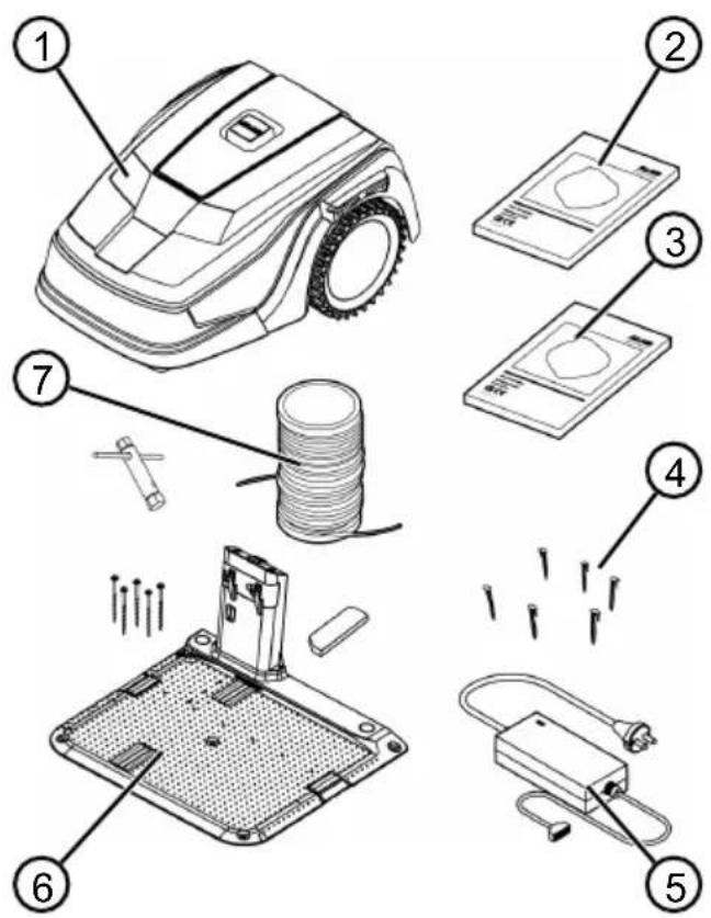
No. Component
| 1 Automatic lawn mower |
| 2 Quickstart guide |
| 3 Operating instructions |
| 4 Lawn pegs * |
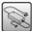
| 5 Power supply |
| 6 Base station incl. screw nails (5 pcs.), wrench and winter cover |
| 7 Boundary cable * |
* not included in the scope of supply
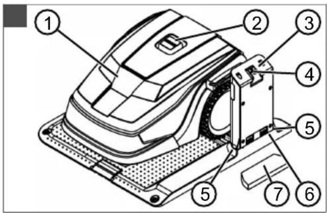
2.2 Automatic lawn mower
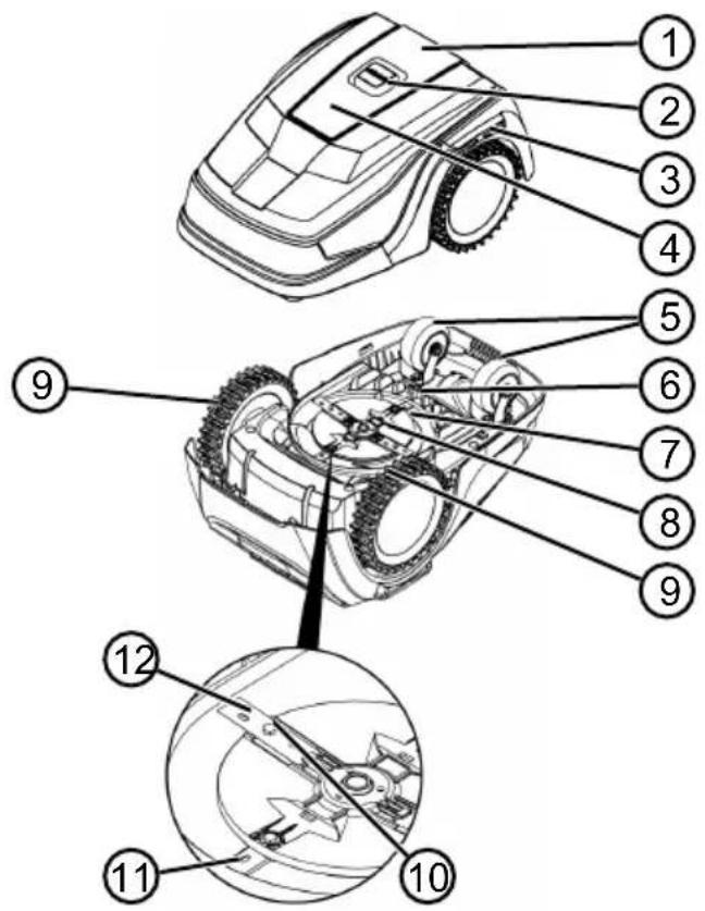
No. Component
| 1 Control panel with display (interior) |
| 2 STOP key (stops the appliance immediately and the cutting blade within 2 s) |
| 3 Charging contacts |
| 4 Height adjustment (interior) |
| 5 Front rollers (steering) |
| 6 Rechargeable battery compartment |
| 7 Mower deck |
| 8 Blade plate |
| 9 Drive wheel |
| 10 Fastening screw |
| 11 Clearer blade |
| 12 Cutting blade |
2.3 Symbols on the appliance
Symbol Meaning

Keep other people out of the danger area!
Pay special attention when handling this product!
Keep your hands and feet away from the blade system!
Maintain a safety distance!
Read the operating instructions before starting operation!
Enter the PIN in order to start the appliance!
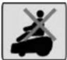
Do not ride on the appliance!
2.4 Control panel
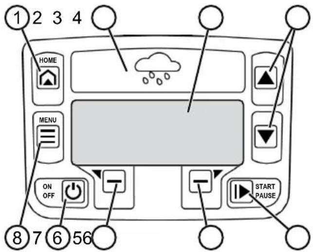
No. Component
| 1 | [WSK6] (home button): Cancel mowing, the  |
| 2 Ra |  |
| 3 Dis | 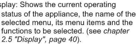 |
| 4 |  arrow keys): Select the menu arrow keys): Select the menu  |
| 5 |  (start/pause button): Start mowing (start/pause button): Start mowing 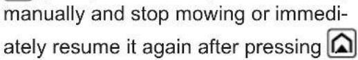 |
| 6 |  function keys): Call up the function keys): Call up the  |
| 7 | [25KY] (On/Off button): Switch the appli- |
| 8 |  (menu button): Call up the main menu. (menu button): Call up the main menu. |
2.5 Display
flowchart
graph TD
    A["1 Main Menu"] --> B["*Settings"]
    B --> C["Information"]
    C --> D["Back"]
    D --> E["Confirm"]
    F["2"] --> G["3"]
    H["3"] --> I["4"]
No. Display
1 Name of the selected menu (here: Main Menu)
2 Menu items in the menu: Only two menu items are ever displayed (here: Settings and Information). Further menu items can be displayed with ▲ and ▼
3 Functions for the selected menu item (here: Settings). Further functions can be called up with ▼ and . —
4 Asterisk for marking the displayed menu item (here: Settings)
2.6 Menu structure
| Main Menu | Programs | Weekly Program see chapter 7.5 "Setting the mowing program", page 53 |
| Entry Point see chapter 7.5.2 "Setting the start points", page 53 | ||
| Program Info see chapter 8 "Displaying information", page 55 | ||
| Settings | Time see chapter 5.2 "Making the basic settings", page 50 | |
| Date see chapter 5.2 "Making the basic settings", page 50 | ||
| Language see chapter 5.2 "Making the basic settings", page 50 | ||
| PIN-Code see chapter 5.2 "Making the basic settings", page 50 | ||
| Key clicks see chapter 7.2 "Activating/deactivating the button tones", page 52 | ||
| EcoMode see chapter 7.3 "Activating/deactivating Eco mode", page 52 | ||
| Rain sensor see chapter 7.4 "Setting the rain sensor", page 52 | ||
| After rain delay see chapter 7.4 "Setting the rain sensor", page 52 | ||
| Rain sensitive see chapter 7.4 "Setting the rain sensor", page 52 | ||
| inTOUCH see chapter 7.6 "inTOUCH", page 54 | ||
| Margin mowing see chapter 7.7 "Edge mowing with a manual start", page 54 | ||
| Sub zone active/disabled see chapter 7.8 "Setting the secondary area mowing", page 54 | ||
| Display contrast see chapter 7.9 "Setting the display contrast", page 54 | ||
| Safety settings see chapter 7.10 "Setting lock", page 54 | ||
| Reset calibration see chapter 7.11 "Recalibrating", page 55 | ||
| Factory reset see chapter 7.12 "Restoring factory settings", page 55 | ||
| Information | Blades service see chapter 8 "Displaying information", page 55 | |
| Hardware see chapter 8 "Displaying information", page 55 | ||
| Software see chapter 8 "Displaying information", page 55 | ||
| Program Info see chapter 8 "Displaying information", page 55 | ||
| Failures see chapter 8 "Displaying information", page 55 |
2.7 Base station
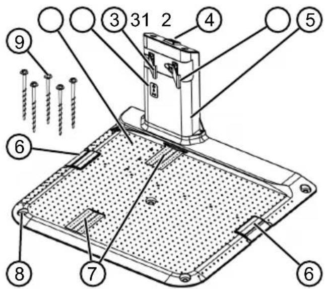
No. Component
| 1 Base plate |
| 2 LEDs for status display |
| 3 Charging contact |
| 4 Home button [IMAGE] |
| 5 Charging station |
| 6 Cable shaft |
| 7 Wheel recess |
| 8 Hole for screw nails (9) |
| 9 Screw nails |
2.8 Integrated battery
The battery is installed permanently in the appliance and may not be changed by the user.

NOTE
Fully charge the rechargeable battery before using it for the first time. The rechargeable battery can be charged in any charge status. Interrupting charging does not damage the rechargeable battery.
The rechargeable battery can only be charged after the appliance has been switched on.
The integrated battery is partially charged on delivery. The battery is regularly recharged during normal operation. The appliance returns to its base station for this.
The integrated electronic control unit with a monitoring function terminates the charging procedure when a 100% charge status is reached.
The charging process only functions with perfect contact of the charging contacts on the base station with the contact surfaces of the appliance.
The built-in protection circuit prevents the battery from being charged at temperatures above 45 °C. This prevents irreparable damage to the battery.
If the operating time of the battery is reduced in spite of it being fully charged, have the battery replaced by a new genuine battery. This task should be carried out by an AL-KO dealer, technician or service partner.
If the battery charge level has dropped below the threshold set by the manufacturer as a result of ageing or excessively long storage, this means it can no longer be recharged. Have the battery and the monitoring electronic control unit checked by an AL-KO dealer, technician or service partner, and replace them if necessary.
The battery status is shown on the display. Check the battery status after about 3 months in storage. To do so, switch on the appliance and read off the battery status. If the rechargeable battery is now only charged to approx. 30% or less, place the appliance in the base station and switch it on so the rechargeable battery is charged. If the charging station was removed to store the base station (see chapter 11.2 "Storing the base station", page 57), first mount it again in reverse order and connect the base station to the mains supply again.
If electrolyte has escaped into the appliance: Have the appliance repaired by an AL-KO service centre.
If the rechargeable battery has been removed from the appliance: If the eyes or hands have come into contact with escaped electrolyte, flush them immediately with water. Immediately consult a doctor.
2.9 Functional description
Moving on the grass surface
The appliance moves freely in a mowing area delimited by a boundary cable. The appliance is oriented by sensors that detect the magnetic field of the boundary cable.
If the appliance encounters an obstacle, it stops and then continues in another direction. If the appliance detects moisture, it automatically returns to the base station. If the appliance gets into a situation where it cannot operate, this is indicated by a message on the display.
Mowing and charging
The mowing phases alternate constantly with the charging phases. If the charge of the rechargeable battery drops to a specific value (display: 0 %) during mowing, the appliance returns to the base station along the boundary cable.
Pre-set mowing programs are available for mowing, and also include the lawn and edge mowing function. These mowing programs can be changed.
Each time the mowing motor is started, its direction of rotation is changed which doubles the service life of the cutting blades.
2.10 Integration in innogy SmartHome
The robot lawn mower can be integrated in an in-nogy SmartHome environment and linked with other appliances. This enables the convenient control, setting and monitoring of the robot lawn mower via app from a mobile appliance.
To do so, the robot lawn mower must be connected with an innogy SmartHome gateway via Lemonbeat and the AL-KO inTOUCH app or the innogy SmartHome app (for Robolinho 700I/1200I/2000I only) must be installed on a mobile appliance.

NOTE
The mobile appliance being used requires a radio connection in order to use innogy SmartHome.
If the radio connection of the mobile appliance is interrupted, no signals can be transmitted to the robot lawn mower.
2.10.1 AL-KO inTOUCH app
The AL-KO inTOUCH app is available for Android-based and iOS-based appliances:

After installing the app, the user must first log in.

NOTE
Registration is not absolutely necessary, but offers some additional functions.
The Quick Installation Guide is automatically called up the first time the app is started. Then, the robot lawn mower can be integrated in the SmartHome environment in the “Appliances” menu.

NOTE
An innogy account is required for integration.

NOTE
The robot lawn mower must be ready to receive in order to be integrated (see chapter 7.6 "inTOUCH", page 54).
Besides remote access to integrated robot lawn mowers or other linked appliances, the AL-KO in-TOUCH app offers other features such as product registration, gardening tips, gardening manual or push notifications in the event of a fault.
2.10.2 innogy SmartHome app (for Robolinho 700I/1200I/2000I only)
The innogy SmartHome app is available for Android-based and iOS-based appliances as well as browser-based web applications.
Further information on the innogy SmartHome app is available at https://home.innogy-smarthome.de as well as in the documentation of the app.
3 SAFETY
3.1 Intended use
This appliance is intended solely for use in non-commercial applications. Any other use (as well as unauthorised conversions or add-ons) are regarded as contrary to the intended use and will result in exclusion of the warranty as well as loss of conformity (CE mark); the manufacturer will thus decline any responsibility for damage and/or injury suffered by the user or third parties.
The application limits of the appliance are:
Max. area:
■ Robolinho 700: 700 m²
■ Robolinho 1200: 1200 m²
■ Robolinho 2000: 2000 m²
■ Max. upward/downward slope: 45 % (24°)
■ Max. lateral inclined angle: 45 % (24°)
■ Temperature:
- Charging: 0 – 45 °C
■ Mowing: 0 – 55 °C
3.2 Possible misuse
This machine is not suitable for use in public gardens, parks, sports stadiums, and in agriculture and forestry.
3.3 Safety and protective devices

WARNING!
Risk of injury
Defective and disabled safety and protective devices can lead to serious injury.
■ Have any defective safety and protective devices repaired.
■ Never disable safety and protective devices.
3.3.1 PIN and PUK input
The appliance can only be started by entering a PIN (Personal Identification Number). This prevents the appliance from being switched on by unauthorised persons. The factory setting of the PIN is 0000. The PIN can be changed, see see chapter 5.2 "Making the basic settings", page 50.
If the PIN is entered incorrectly 3 times, the PUK (Personal Unlocking Key) must be entered. If this is also entered incorrectly, the user must wait 24 hours until entering it again.
The PIN and PUK input also serves as an anti-theft device:
- Keep the PIN and PUK so that they are inaccessible to unauthorised persons.
3.3.2 Sensors
The appliance is provided with several safety sensors. It does not restart automatically after being switched off by a safety sensor. The error message is shown on the display and must be acknowledged. The reason for the triggering of the sensor must be resolved.
Lifting sensor
If the appliance is raised by the housing during operation, the travel drive switches off and the cutting blades are stopped.
Bump sensors for obstacle detection
The appliance is equipped with sensors that ensure it changes its direction of travel if it encounters obstacles. When it encounters an obstacle, the top part of the deck is shifted slightly and the shock sensor triggered.
Tilt sensor in direction of travel/sideways
If an upward or downward slope or a laterally inclined angle of 24^ (45 %) is reached in the direction of travel, the appliance is turned or the appliance changes its direction of travel.
Rain sensor
The appliance is equipped with a rain sensor that (when activated) interrupts the mowing procedure in case of rain, and ensures that the appliance returns to the base station.

NOTE
The appliance can be operated reliably in the immediate vicinity of other automatic lawn mowers. The signal used in the boundary cable corresponds to the standard defined by the European Garden Machinery Industry Federation (EGMF) with regard to electromagnetic emissions.

3.4 Safety instructions
3.4.1 Operator
■ Young people under 16 years of age, persons with limited physical, sensory or mental abilities or with a lack of experience and knowledge and persons who do not know the
operating instructions must not use the device. Heed any country-specific safety regulations concerning the minimum age of the user.
■ Do not operate the appliance if you are under the influence of alcohol, drugs or medication.
3.4.2 Personal protective equipment
■ Wear clothing and protective equipment in accordance with the regulations in order to avoid injury.
■ The personal protective equipment comprises:
- Long trousers and sturdy shoes.
■ During maintenance and care: Protective gloves.
3.4.3 Safety of persons and animals
In areas accessible to the public, affix warning information with the following content around the mowing area:

IMPORTANT!
Automatic lawn mower in operation!
Do not approach the appli- ance!
Supervise children.
■ Make sure that children and other persons are not present in the vicinity of the appliance when it is operating or climb onto the appliance and do not play with the appliance.
■ Sitting on the appliance and reaching into the cutting blade is forbidden.
- Keep body and clothes away from the cutting unit.
3.4.4 Appliance safety
■ Before working, make sure that there are no objects (e.g. branches, glass or metal pieces, and items of clothing, stones, garden furniture, garden utensils or toys) in the work area of the appliance. They can damage the cutting blade of the appliance or can be damaged by the appliance.
■ Only use the appliance under the following conditions:
■ The appliance is not soiled.
■ The appliance shows no damage or wear.
■ All controls function properly.
- The base station and power supply as well as their electrical supply cables are undamaged and function properly.
■ Always replace defective parts with original spare parts from the manufacturer.
■ Have the appliance repaired if it has been damaged.
■ The user of the appliance is responsible for accidents of the appliance involving other persons or their property.
3.4.5 Electrical safety
■ Never operate the appliance when a lawn sprinkler is operating on the mowing area at the same time.
■ Do not spray the appliance with water.
■ Do not open the appliance.
4 INSTALLATION
4.1 Unpacking the machine
- Open the packaging carefully.
- Carefully remove all components from the packaging and check for transport damage. Note: If there is any transport damage, immediately notify your AL-KO dealer, technician or service partner in accordance with the warranty conditions.
- Check the scope of supply, see chapter 2.1 "Scope of supply", page 38.
If the appliance is going to be sent on, retain the original packaging and accompanying documents. They will also be required for return shipment.
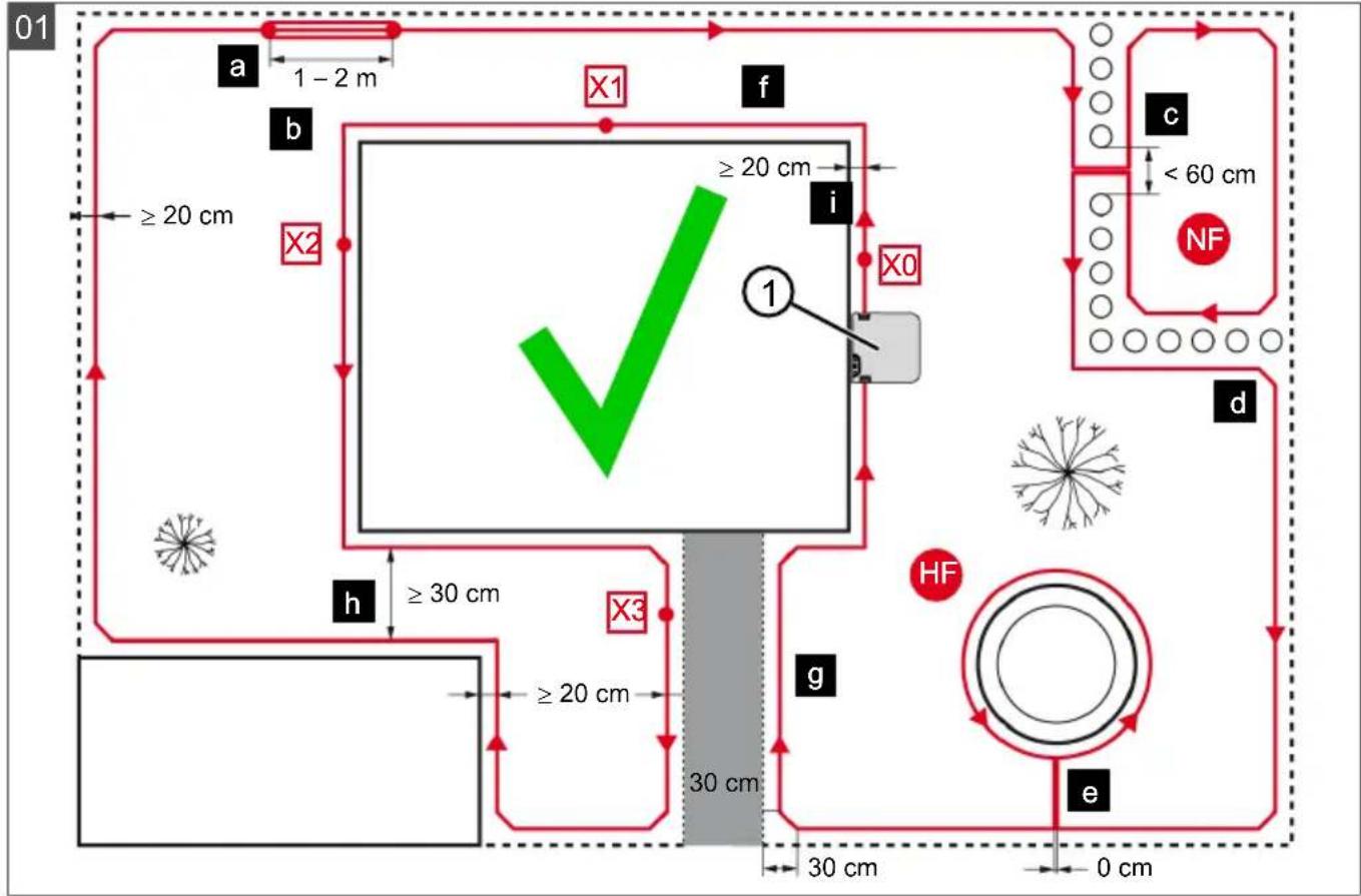
4.2 Planning the mowing areas (01)
Location of the base station (01/1)
■ Shortest possible distance to the largest mowing area
Level surface
■ Protected against direct sunlight and harsh weather conditions
■ Connection option for power source
■ Free accessibility to the robot lawn mower
Routing the boundary cable (01)
The boundary cable must be laid in a continuous loop in a clockwise direction.
Corridors between mowing areas (01/h)
A corridor is a narrow section in the grass surface and can be used to connect two mowing areas.
Main area and secondary area(s) (01)
■ Main area (01/HF): This is the grass surface on which the base station is located and whose entire surface can be mowed automatically by the appliance.
Secondary area (01/NF): If a grass surface cannot be reached by the appliance from the main area, carry the appliance to the secondary area by hand if necessary. Secondary areas can be processed using manual operation.
The main area and secondary areas are bounded by the same continuous boundary cable, however.
Location of start points (01/X0 - 01/X3)
At the specified mowing time, the appliance moves along the boundary cable to the specified start point and begins to mow there.
The start points can be used to specify which areas of the mowing area are to be mowed several times.
4.3 Preparing the mowing areas
- Check that the grass surface is larger than the area covered by the appliance. If the grass surface is too large, an irregularly mown lawn will result. Reduce the size of the grass surface to be mowed if necessary.
- Before installation of the base station and boundary cable or start-up of the appliance: Use a lawn mower to mow the grass surface to a low cutting height.
- Remove any obstacles on the grass surface or exclude them with the boundary cable (see chapter 4.5.3 "Excluding obstacles", page 48):
- Flat obstacles that will be run over and could damage the cutting blade (e.g. flat stones, transitions from the grass surface to the terrace or paths, plates, kerbstones, etc.)
■ Holes and protrusions in the grass surface (e.g. molehills, burrowing holes, pine cones, fallen fruit, etc.)
■ Steep ascents and descents of more than 45 % (24°)
■ Bodies of water (e.g. ponds, streams, swimming pools, etc.) and their demarcation to the grass surface
■ Shrubs and hedges that can become broader
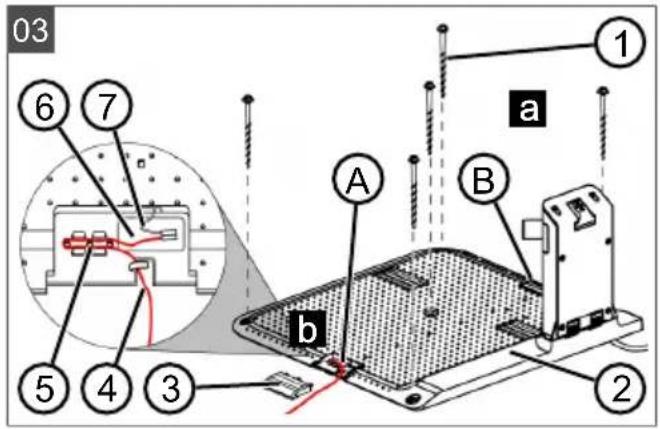
4.4 Setting up the base station (03/a)
- Place the base station (01/1) at right angles to the planned location of the boundary cable as described below:
■ Level (check with spirit level)
■ Straight and level entrance and exit
■ Not arched (the charging station must not bend or tilt during subsequent tightening of the screw nails)
- Fix the base station (03/2) to the floor with four screw nails (03/1).
4.5 Installing the boundary cable
4.5.1 Connecting the boundary cable to the base station (03/b)
- Pull the boundary cable (03/4) out of the packaging.
- Remove the cover of the cable shaft (03/3) on the connection (03/A).
- Insulate the end of the boundary cable (03/6) and insert into the terminal (03/7).
- Close the terminal.
- Lead the boundary cable through the strain relief (03/5) out of the cable shaft with cable reserve.

NOTE
The cable reserve allows smaller corrections to be carried out on the cable guide later.
- Place the cover on the cable shaft.
4.5.2 Routing the boundary cable (01)
The boundary cable can be laid on the lawn and as much as 10 cm under the turf. Laying under the turf can be carried out by the dealer.
Both variants can be combined with one another.
IMPORTANT!
Danger of damaging the boundary cable
If the boundary cable is damaged or cut, the transmission of the control signals to the appliance is no longer possible. In this case, the boundary cable must be repaired or replaced. The boundary cables are available from AL-KO.
■ Always route the boundary cable directly on the ground. If necessary, secure with an additional lawn peg.
■ When laying the boundary cable and during operation, protect the boundary cable from damage.
- Do not dig or scarify in the vicinity of the boundary cable.
- Attach the boundary cable at regular intervals with lawn pegs or route it underground (at a max. depth of 10 cm).
- Route the boundary cable around obstacles: see chapter 4.5.3 "Excluding obstacles", page 48.
- Create corridors between individual mowing areas: see chapter 4.5.4 "Enclosing corridors (01/h)", page 49.
- Exclude excessive upward or downward slopes: see chapter 4.5.5 "Excluding downward slopes", page 49.
- Create loops of cable: see chapter 4.5.6 "Creating loops of cable (07)", page 49.
- After completing the routing of the boundary cable, connect to the connector (03/B) of the base station: see chapter 4.5.1 "Connecting the boundary cable to the base station (03/b)", page 48.
4.5.3 Excluding obstacles
Depending on the surroundings of the working area, the boundary cable must be routed at different distances to obstacles. Use the ruler that can be removed from the packaging to determine the correct distance.

NOTE
Exclusions are only necessary if they cannot be detected by the bump sensors of the appliance. Avoid too many or unnecessary exclusions.
Recesses that are smaller than 6 cm must be excluded, otherwise the appliance may cause damage.
Distance from walls, fences, beds: min. 20 cm (01)
The appliance moves along the boundary cable with an offset of 20 cm to the outside. Therefore, route the boundary cable at a distance of at least 20 cm from walls, fences, beds, etc.
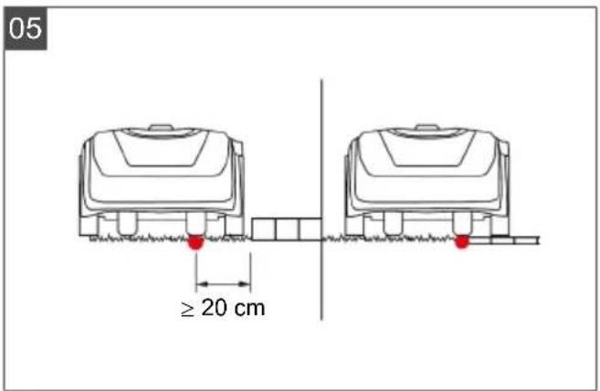
Distance from terrace edges and paved paths (05)
If the terrace or path edge is higher than the grass surface, a distance of at least 20 cm must be complied with. If the edge of the terrace or path is at the same height as the grass surface, the cable can be routed exactly along the edge.
Distance of obstacles from the boundary cable (01)
If the boundary cables are precisely folded up away from the obstacle or towards the obstacle, i.e. distance 0 cm, the appliance moves beyond the boundary cable. Do not cross the boundary cables (02/c), but lay them parallel (01/e).
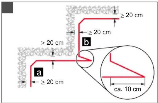
Routing the boundary cable around corners (06)
For inwards going corners (06/a): Route the boundary cable diagonally to avoid the appliance becoming caught in the corner.
For outwards going corners with obstacles (06/b): Route the boundary cable in a point in order to avoid a collision of the appliance with the corner.
For outwards going corners without obstacles: Route the boundary cable at an angle of 90°.
4.5.4 Enclosing corridors (01/h)
In the corridor the following distances must be complied with:
■ Total width: min. 60 cm
■ Distance of the boundary cable to the edge: 20 cm
■ Distance between the boundary cables: min. 30 cm
4.5.5 Excluding downward slopes
Downward slopes that are greater than 45 % must be excluded with the boundary cable (45 % = 45 cm downward slopes per 1 m horizontally).
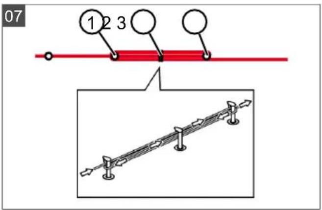
4.5.6 Creating loops of cable (07)
Spare loops of cable should be incorporated at regular intervals in order to reposition the base station or to extend the mowing area even after the mowing area has been laid out.
Select the number of spare cable loops according to your own judgement.

NOTE
In the case of spare cable loops, do not form open loops.
- Lead the boundary cable around the current lawn peg (07/1) and then back to the previous lawn peg (07/3).
- Then lead the boundary cable to the current lawn peg again. This creates a loop. The cables must be close together.
- If necessary, attach the loop to the ground in the middle with an additional lawn peg (07/2).
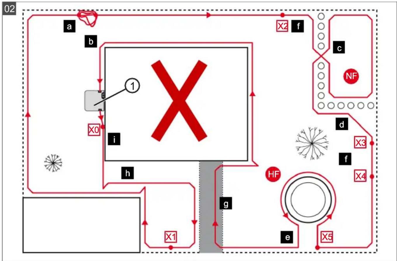
4.5.7 Typical faults in cable routing (02)
- Spare cable loops of the boundary cable are not laid in an even, elongated loop (02/a).
■ The boundary cable is not routed properly around corners (02/b).
■ The boundary cable is crossed over or not routed clockwise (02/c).
The boundary cable is routed too imprecisely so that edge areas of the grass surface cannot be mowed (02/d).
The boundary cable is not routed lying directly next to itself when guided towards and back from the edge to an obstacle inside the lawn (02/e).
■ The start points are set too far away from the base station (02/f).
■ The boundary cable is routed beyond the edge of the grass surface (02/g).
■ When routing the boundary cable, the minimum distance for corridors of 30 cm is undercut (02/h).
The boundary cable is routed too close (i.e. at a distance of less than 20 cm) to obstacles that cannot be driven over (02/i).
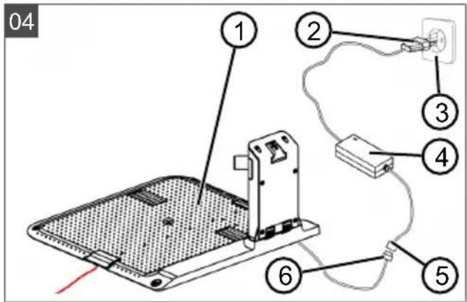
4.6 Connecting the base station to the power source (04)
- Place the power supply (04/4) in a dry location that is protected against direct sunlight and sufficiently close to the base station (04/1).
- Connect the low voltage cable of the power supply (04/5) and the cable of the base station (04/6) with each other.
- Plug the power plug of the power supply (04/2) into a power socket (04/3).

NOTE
We recommend connecting the power supply to the mains supply via an earth leakage circuit breaker (ELCB) with a rated leakage current < 30 mA.
4.7 Checking the connections on the base station (04)
- Check that both LEDs on the front side of the charging station (09/1) light. If not:
■ Disconnect the mains plug.
- Check that all plug connectors of the power source and the boundary cable are positioned correctly and check for damage.
Status indications of the LEDs
| LEDs Operating states | |
| Green | Lights up when the boundary cable is laid correctly and the loop is intact.Flashes if a loop of the boundary cable is not in order. |
| Yellow | Lights up if the power source is intact. |
5 START-UP
This chapter describes the activities and settings that are necessary to put the appliance into operation for the first time. For all further settings, refer to see chapter 7 "Settings", page 52.
5.1 Charging the rechargeable battery (08)
The integrated battery is partially charged on delivery. During normal operation, the battery of the appliance is regularly charged automatically.

NOTE
Fully charge the rechargeable battery before using it for the first time. The rechargeable battery can be charged in any charge status. Interrupting charging does not damage the rechargeable battery.
The rechargeable battery can only be charged after the appliance has been switched on.
- Place the appliance (08/1) in the base station (08/3) so the contact surfaces of the appliance touch the charging contacts of the base station.
- Switch on the appliance with
- The display on the appliance shows Battery is being recharged. If not: see chapter 14 "Help in case of malfunction", page 59.
5.2 Making the basic settings
- Open the cover flap.
- Switch on the appliance with .the firmware, code number and type are displayed.
- In the menu for language selection, use ▲ or ▼ to select the language and accept with —.
- In the Login > Enter PIN menu, enter the preset PIN 0000. To do so, select the digit 0 in sequence with ▲ and respectively confirm with □. After entering the PIN, access is enabled.
- In the Change PIN menu:
■ Under Enter new PIN, enter a self-selected new four-digit PIN. To do so, select one digit in sequence with ▲ and respectively confirm with —
■ Under Reenter new PIN, enter the new PIN again. If both entries are identical, PIN changed is displayed.
-
In the Enter date menu, set the current date (format: DD.MM.20YY). To do so, select one digit in sequence with ▲ and re-spectively confirm with —
-
In the Enter time > HH:MM menu, set the current time (format: HH:MM). To do so, select one digit in sequence with ▲ and respectively confirm with —
The basic settings have been completed. The Not calibrated Press Start key status is displayed.
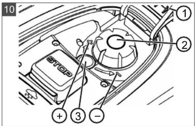
5.3 Setting the cutting height
The cutting height can be manually adjusted continuously between 25 - 55 mm.

NOTE
A cutting height of 55 mm is recommended for the calibration movement (see see chapter 5.4 "Carrying out an automatic calibration movement", page 51) and for teaching the starting points (see see chapter 7.5.2 "Setting the start points", page 53).
- Open the cover (10/1).
- Set the cutting height (the current cutting height is displayed in the window (10/3) in millimetres):
■ Increase the cutting height (i.e. lawn height): Turn the rotary knob (10/2) clockwise (10/+).
■ Decrease the cutting height (i.e. lawn height): Turn the rotary knob (10/2) anticlockwise (10/−).
- Close the cover.
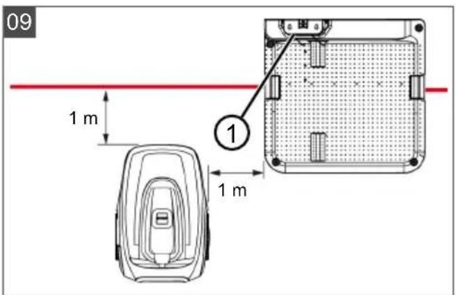
5.4 Carrying out an automatic calibration movement
Place the appliance at the starting position (09)
- Place the appliance at the starting position inside the mowing area:
At least 1 m left and 1 m in front of the base station
■ Aligned with the front side to the boundary cable
Starting the calibration movement
-
Check that there are no obstacles in the expected movement area of the appliance. The appliance must be able to move over the boundary cable with both front wheels. Remove any obstacles if necessary.
-
Start the appliance with .the following is shown on the display:
■ ! Caution ! Starting Motors
■ Calibration, Phase [1]
During the calibration movement
To determine the signal strength inside the boundary cable, the appliance first moves twice straight beyond the boundary cable and then into the base station and comes to a stop there.
■ The Calibration completed message is shown on the display.
■ The rechargeable battery is being charged.

NOTE
The appliance must come to a stop when it moves into the base station. If the appliance does not touch the contacts when it moves into the base station, it moves further along the boundary cable. If the appliance moves through the base station, the calibration procedure has failed. In this case, the base station must be better aligned and the calibration procedure repeated.
After the calibration movement
The preset current mowing duration is displayed. For all further settings, refer to see chapter 7 "Settings", page 52.

NOTE
To ensure clean mowing, it is recommended to have the appliance measure the loop length. This is done with the teaching-in movement to determine the start points (see chapter 7.5.2 "Setting the start points", page 53).
6 OPERATION
6.1 Starting the appliance manually
- Switch on the appliance with . For unscheduled edge mowing: see chapter 7.7 "Edge mowing with a manual start", page 54.
- Start the appliance manually with .
6.2 Cancelling mowing
■ Press on the base station (08/4) or on the appliance.
The appliance moves automatically into the base station. It deletes the mowing plan of the current day and starts again the next day for the set time.
- Press ▶ in the appliance.
The mowing is interrupted for half an hour.
■ Press ☐ on the appliance.
The appliance is switched off.

NOTE
In dangerous situations, the appliance can be stopped with the STOP button (08/2).
6.3 Mowing the secondary area (01/NF)
- Lift the appliance and place in the secondary area by hand.
- Switch on the appliance with .
- Call up the main menu with .☐
- o▲* Settings
- o▲* sub zone mowing
- Select the mowing time with ▲. ▼
- Start the appliance manually with .
Depending on the setting: The appliance mows for the set time period and then switches off or mows until the rechargeable battery is flat.
After mowing the secondary area, place the appliance in the base station again by hand.
7 SETTINGS
7.1 Calling up the setting – General
- Call up the main menu with .☐ Note: The asterisk * in front of the menu item indicates that it has just been selected.
- or* Settings
- Select the required menu item with ▲ ▼ and accept with —
- Make the settings. Note: The menu items are described in the following sections.
- Return to the main menu with .☐

NOTE
Further menu items: see chapter 5.2 "Making the basic settings", page 50.
7.2 Activating/deactivating the button tones
-
or * Key clicks
-
Activating/deactivating the button tones:
or Activate : — Activate the button tones.
or deactivate : — Deactivate the button tones.
7.3 Activating/deactivating Eco mode
In Eco mode, the appliance switches to energy-saving mode. This reduces the energy consumption and noise emissions.

NOTE
With high and thick grass and for thick rolled turf, this is not recommended or may not be possible.
-
or * EcoMode
-
Activating/deactivating Eco mode:
■ Activate — Activate Eco mode.
■ Deactivate — Deactivate Eco mode.
7.4 Setting the rain sensor

NOTE
Mowing when the grass is dry reduces soiling.
By activating the rain sensor and setting a delay time, it is possible to prevent the appliance mowing when the grass is wet.
If the rain sensor is activated, the appliance moves back into the base station when the rain begins. It remains there until the rain sensor has dried. Then it waits for the time period that is set as the delay before it continues mowing. The sensitivity of the rain sensor is adjustable.
-
or * Rain sensor
-
Activating/deactivating the rain sensor:
or Activate : — Activate the rain sensor.
or deactivate : — Deactivate the rain sensor.
- Setting the delay of the rain sensor:
or After rain delay
- xx hours xx minutes Select the required value for the delay with ▲ and ▼ accept with .
- Setting the sensitivity of the rain sensor:
or Rain sensitive
■ Select the required value for the sensitivity with ▲ and accept with .
7.5 Setting the mowing program
7.5.1 Setting the mowing program – General
-
Call up the main menu with .
-
or* Programs
-
Select the menu item with ▲ and ▼ accept with —
-
Carry out the settings. Note: The menu items are described in the following sections.
7.5.2 Setting the start points
Teaching-in start points
-
Place the appliance in the base station.
-
Switch on the appliance with .
-
Call up the main menu with .☐
-
or* Programs
-
or* Entry Point
-
or* Interactive teach
-
o▲* Start interactive entry point teaching —
or start. The appliance moves along the boundary cable.
or set when the appliance has reached the required start point. The start point is stored.
-
o▲Set▼entry point 1 if no — start point has been specified during the teaching-in movement. If no start point has been specified here, the start points are automatically specified.
-
or▲Entry point x: XXm if the last start point has been reached.
Manually specifying start points (01)
The first start point (01/X0) is pre-set and is 1 m to right of the base station. Other start points can be defined after this point:
■ Robolinho 700: up to three start points (X1 – X3)
■ Robolinho 1200: up to six start points (X1 – X6)
■ Robolinho 2000: up to nine start points (X1 – X9)
When specifying the start points, heed the following:
■ Do not set start points too far from the base station or too close to one another (02/f).
■ Only use as many start points as necessary.
-
or* Entry Point
-
o* Point x1 at [020m] Select one digit in sequence with ▲ and accept accordingly with -
-
on* Point x2 at [075m] Select one digit in sequence with ▲ and respectively accept with —
-
If necessary, specify further start points.
-
Return to the main menu with .☐
7.5.3 Setting the mowing times

NOTE
There must be at least 30 min. between programming the mowing times and the mowing start. If not, the appliance only starts at the next programmed mowing time.
In the weekly Program menu item, the days of the week and time periods when the appliance should mow are set. Adapt these settings to the size of your garden if necessary. If unmown areas are still visible after approx. one week, increase the mowing periods.
- on* Weekly Program
or ▲ All Days [X]: The appliance mows every day at the set times. If All Days [ ] is shown, the appliance only mows on the set days of the week.
or ▲ Monday [X]...* Sunday [X]: The appliance mows for the set time periods on the set day of the week. If Monday [ ] is shown, for example, the appliance does not mow on the respective day.
or ▲ change : Activate the respective day [X] or deactivate it [ ], and set the time periods, type of mowing and the start points.
- Make the settings for every day or the respective day:
e.g. *[M] 07:00-10:00 [?]: Normal mowing [M] from 07:00 - 10:00 am with automatically changing start point 0 - 9 [?].
e.g. *[R] 16:00-18:00 [1]: The appliance starts with edge mowing [R] at 4 pm and moves along the entire boundary cable. The area mowing then begins at start point 1 [1]. At 6 pm or as soon as the rechargeable battery is discharged, the appliance moves back to the base station.
or Change : Change the selected setting.
or continue : Confirm the changes setting and continue to the next setting.
- or ▲ Save : Save all changed settings of the menu item.
7.6 inTOUCH
An existing connection to a gateway can be disconnected. This means the appliance is ready to establish a new connection for 30 minutes.

NOTE
To establish a connection later, the connection must first be disconnected again, even if the appliance was not previously connected with a gateway.
-
or*inOUCH
-
Reset connection Appliance reports: Done.
- Confirm with and return to the menu.
7.7 Edge mowing with a manual start
For a manual start, the setting can be made here that the appliance begins with edge mowing.
Carrying out the edge mowing at the programmed mowing time periods: see chapter 7.5.3 "Setting the mowing times", page 53.
- o▲* Margin mowing
- o▲* a manual start
7.8 Setting the secondary area mowing
-
o▲* Sub zone mowing
-
Setting the mowing time periods:
or inactive : —
Secondary area mowing is switched off.
or active : The appliance mows until the rechargeable battery is flat.
or mowing time in min : The appliance mows the secondary area for the set time period. The following mowing time periods can be set: 30/60/90/120/until rechargeable battery flat.
7.9 Setting the display contrast
If the display is difficult to read, e.g. in sunlight, the display can be improved by changing the display contrast.
- or* display contrast
- Increase/decrease the display contrast with
or and accept with .
7.10 Setting lock
If the setting lock is deactivated, the PIN must only be entered when acknowledging safety-relevant faults.
- or* safety settings
- Activating/deactivating the setting lock:
or Activate : —
Activate the setting lock.
or deactivate : —
Deactivate the setting lock.
7.11 Recalibrating
If the position or length of the boundary cable has been changed or the appliance no longer finds the boundary cable, recalibration is necessary.
- or Reset calibration
- Reset loop calibration data?
- Carrying out a calibration movement: see chapter 5.4 "Carrying out an automatic calibration movement", page 51.
7.12 Restoring factory settings
The factory settings of the appliance can be restored, e.g. before selling the appliance.
- o▲* Factory reset Appliance reports: Factory reset completed
8 DISPLAYING INFORMATION
The Information menu is used for displaying machine data. No settings can be made in this menu.
- Call up the main menu with .
- or* Information
- Select the menu item with ▲ and ▼ accept with ▼
Note: The menu items are described in the following sections.
- Return to the main menu with .☐
Blades service
Shows in how many operating hours a blade service is required. The counter can be reset manually. Have the blade service carried out by an AL-KO dealer, technician or service partner.
Reset the counter for blade service:
- or Confirm
Hardware
Shows information on the appliance, such as type, year of manufacture, operating hours, serial identification number, number of mowing inserts, total mowing time, number of charging cycles, total charging time, length of the loop of the boundary cable.
Software
Shows the firmware version.
Program Info
Shows current settings such as the total weekly mowing time.
Failures
Shows the fault messages that last occurred with date, time and fault code.
9 MAINTENANCE AND CARE

CAUTION!
Risk of injury
Sharp-edged and moving appliance parts can lead to injury.
■ Always wear protective gloves during maintenance, care and cleaning work.
9.1 Cleaning
IMPORTANT!
Danger from water
Water in the automatic lawn mower and in the base station leads to damage on electrical components.
- Do not spray the automatic lawn mower and base station with water.
Clean the automatic lawn mower

CAUTION!
Danger of injury due to the cutting blade
The cutting blades are very sharp and can cause cutting injuries.
■ Wear protective gloves.
■ Make sure that parts of the body do not get into the cutting blade.
Once a week, carry out the following:
- Switch off the appliance with

-
Wipe off the surface of the housing with a broom, a brush, a damp cloth or a fine sponge.
-
Brush off the underside, mower deck and cutting blade with a brush.
-
Check the cutting blade for damage. If necessary, replace the following: see chapter 9.3 "Replacing the cutting blades", page 56.
Cleaning the base station
-
Regularly remove grass residues and leaves or other objects out of the base station.
-
Wipe off the surface of the base station with a damp cloth or a fine sponge.
9.2 Regular checks
General checks
- Once a week, check the whole Installation for damage:
Machine
Base station
■ Boundary cable
Power supply
- Replace defective parts by original spare parts from AL-KO or have them replaced by an AL-KO service centre.
Check the rollers can move freely
Once a week, carry out the following:
- Carefully remove grass residues and soiling from the areas around the rollers. Use a broom and cloth for this.
- Check that the rollers run freely and that they can be steered.
Note: If the rollers do not move freely or cannot be steered, have them replaced by an AL-KO service centre.
Check the contact surfaces on the automatic lawn mower
- Use a cloth to remove soiling and then lightly grease with contact grease.
Check the charging contacts of the base station
- Disconnect the mains plug.
- Press the charging contacts in the direction of the base station and release them. The charging contacts must spring back into the initial position.
Note: If the charging contacts do not spring back, have them replaced by the AL-KO service centre.
9.3 Replacing the cutting blades

CAUTION!
Danger of injury due to the cutting blade
The cutting blades are very sharp and can cause cutting injuries.
■ Wear protective gloves.
■ Make sure that parts of the body do not get into the cutting blade.
IMPORTANT!
Damage to the appliance due to incorrect repair
The blade plate can be damaged by the alignment of a bent, built-in cutting blade.
■ Do not align bent cutting blades.
- Replace bent cutting blades by original spare parts from AL-KO.
Worn or bent cutting blades must be replaced.
- Switch off the appliance with
- Put down the appliance with the cutting blades pointing upwards.
- Unscrew the fastening screws.
- Take the cutting blade out of the blade seat.
- Clean the blade seat with a soft brush.

NOTE
The cutting blades are sharpened along the entire length and can therefore also be mounted rotated by 180^ , which doubles their runtime.
- Replacing the cutting blades:
If cutting blades have not been rotated since the initial mounting: Rotate the cutting blades by 180° and insert into the blade seat again with the sharpened side pointing towards the appliance, and tighten the fastening screws again by hand.
If the cutting blades have already been rotated once since the initial mounting: Insert new cutting blades into the blade seat again with the sharpened side pointing towards the appliance, and tighten the new fastening screws by hand.
Note: It is only allowed to use original spare parts from AL-KO.
As a rule, the clearer blades do not need to be replaced.
In case of stubborn dirt that cannot be removed with a brush, the blade plate must be replaced because an imbalance can lead to increased noise levels, greater wear and malfunctions.
10 TRANSPORT
For transporting the appliance, e.g. from the main area to the secondary area, proceed as follows:
- Stop the appliance with ton.
d the stop but-
- Switch off the appliance with

- Lift the appliance with both hands on the housing:
■ Do not touch the cutting blades.
■ The cutting blades must always point away from the body.
11 STORAGE
11.1 Storing the automatic lawn mower
The appliance must be stored over winter or when it is to be taken out of service for an expected duration of longer than 30 days.
-
Fully charge the rechargeable battery (see chapter 5.1 "Charging the rechargeable battery (08)", page 50).
-
Thoroughly clean the appliance (see chapter 9.1 "Cleaning", page 55).
-
Store the appliance:
■ upright on all wheels
■ at a dry, lockable location protected from frost
■ out of the reach of children
11.2 Storing the base station
The base station can, but does not have to be put into storage. Storage prevents premature ageing, however, such as fading of the colour or corrosion of the charging contacts.
If the base station remains outdoors:
-
Disconnect the power supply from the mains supply and unplug from the base station.
-
Roll up the cables of the base station.
-
Store the power supply.
-
Grease the charging contacts with contact grease.
When the base station is to be put into storage:
-
Carry out all work mentioned above.
-
Disconnect the base station from the boundary cable.
-
Remove the base station and remove any soiling with a broom and a slightly damp cloth.
-
Store the base station:
■ at a dry, lockable location protected from frost
■ out of the reach of children
If only the charging pole is stored:
-
Disconnect the power supply from the mains supply and unplug from the base station.
-
Disconnect the base station from the boundary cable.
-
Remove any soiling with a broom and a slightly damp cloth.
-
Removing the charging pole:
■ Unscrew both screws of the charging station (08/5).
■ Remove the charging station from the base station by tilting.
■ Undo the plug connection of the cables from the base station and charging station.
■ Close the opening of the base (08/6) with the included winter cover (08/7).
- Store the base station:
■ at a dry, lockable location protected from frost
■ out of the reach of children
11.3 Winter storage of the boundary cable
The boundary cable can remain in the ground and does not need to be removed.
- When the base station has been put into storage: Grease the cable ends with contact grease and wrap with adhesive tape. This protects the cable ends against corrosion.
12 DISPOSAL
Information on the German Electrical and Electronic Equipment Act (ElectroG)

■ Electrical and electronic appliances do not belong in household waste, but should be collected and disposed of separately.
■ Used batteries or rechargeable batteries that are not installed permanently in the old appliance must be removed before disposal. Their disposal is regulated by the battery law.
- Owners or users of electrical and electronic appliances are obliged by law to return them after use.
■ The end user bears personal responsibility for deleting his personal data from the old appliance to be disposed of.
The symbol of the crossed-through rubbish bin means that electrical and electronic appliances may not be disposed of in the household rubbish.
Electrical and electronic appliances can be handed in at no charge at the following places:
■ Public service disposal or collection points (e.g. municipal building yards)
■ Points of sale of electrical appliances (stationary and online) provided traders are obliged to take them back or offer this voluntarily.
These statements only apply to appliances that are installed and sold in the countries of the European Union and are subject to European Directive 2012/19/EU. Different provisions may apply to the disposal of electrical and electronic appliances in countries outside the European Union.
Information on German Battery Act (BattG)

■ Used batteries and rechargeable batteries do not belong in household waste, but should be collected and disposed of separately.
For safe removal of batteries or rechargeable batteries from the electrical appliance and for information on their type or chemical system, follow the further information within the operating or installation instructions.
- Owners or users of batteries and rechargeable batteries are obliged by law to return them after use. The return is limited to the handover of customary household quantities.
Used batteries can contain harmful substances or heavy metals that can cause damage to the environment and human health. Reuse of the used batteries and use of the resources contained therein contributes to the protection of these two essential commodities.
The symbol of the crossed-through rubbish bin means that batteries and rechargeable batteries may not be disposed of in household rubbish.
In addition, if the symbol Hg, Cd or Pb appears under the rubbish bin, this stands for the following:
■ Hg: Battery contains more than 0.0005 % mercury
Cd: Battery contains more than 0.002 % cadmium
■ Pb: Battery contains more than 0.004 % lead
Rechargeable batteries and batteries can be handed in at the following places at no charge:
■ Public service disposal or collection points (e.g. municipal building yards)
■ Points of sale of batteries and rechargeable batteries
■ Disposal points of the common take-back system for the used batteries of appliances
■ Disposal point of the manufacturer (if not a member of the common take-back system)
These statements apply only to rechargeable batteries and batteries that are sold in the countries of the European Union and that are subject to European Directive 2006/66/EU. Different provisions can apply to the disposal of rechargeable batteries and batteries in countries outside the European Union.
13 AFTER-SALES / SERVICE
In the event of questions of warranty, repair or spare parts, please contact your nearest AL-KO Service Centre. These can be found on the Internet at:
www.al-ko.com/service-contacts
14 HELP IN CASE OF MALFUNCTION
14.1 Correcting appliance and handling faults

CAUTION!
Risk of injury
Sharp-edged and moving appliance parts can lead to injury.
■ Always wear protective gloves during maintenance, care and cleaning work.
| Malfunction Cause Remedy | ||
| The appliance does not start. | Rechargeable battery is flat. Charge the appliance in the base station. | |
| The appliance gets stuck and has dug itself in. The wheels continue to turn. | Bump sensors do not trigger. Contact an AL-KO service centre. | |
| The grass is too high. | ■ Increase the cutting height, then lower in stages to the required height. ■ Mow the grass short with a lawn mower. | |
| The appliance sits on an unevenness of the grass surface. | Eliminate the unevenness. | |
| The appliance mows at the wrong time. | The appliance has the incorrect time. | Set the time. |
| The mowing duration is incorrectly set. | Set the mowing times. | |
| The appliance loses the time settings. | The rechargeable battery is defective. Contact an AL-KO service centre. | |
| Motor stops during mowing. | Motor is overloaded. Switch off the appliance, set on level ground or shorter grass and restart. | |
| Rechargeable battery is flat. Charge the rechargeable battery. | ||
| The cutting blades are blunt. Turn over or replace cutting blades if necessary. | ||
| Mowing result is uneven. Mowing time is too short. Program longer mowing times. | ||
| Malfunction Cause Remedy | ||
| Rechargeable battery operating time is significantly shorter. | Cutting height level is too low. | Increase the cutting height, then lower in stages to the required height. |
| Grass is too long or too wet. | Let the grass dry.Set the cutting height to a higher level. | |
| Appliance vibrates or the volume is too high. | Imbalance on the cutting blade or in the cutting blade drive | Clean the mower deck.Contact an AL-KO service centre. |
| Rechargeable battery cannot be charged or low battery voltage | The charging contacts of the base station are dirty.The contact surfaces on the appliance are soiled. | Clean the charging contacts and contact surfaces. |
| Base station has no power. Connect the base station to the power source. | ||
| The appliance does not touch the charging contacts.The contact surfaces on the appliance are burned out. | Place the appliance in the base station and check that the charging contacts make contact.Contact an AL-KO service centre. | |
| The service life of the rechargeable battery has expired. | Contact an AL-KO service centre. | |
| The charging electronics are faulty. | Contact an AL-KO service centre. | |

NOTE
If you encounter any malfunctions that are not listed in this table or that you cannot rectify yourself, please contact our customer service.
14.2 Fault codes and troubleshooting
| Fault code Cause Remedy | ||
| CN001: Tilt sensor The inclination sensor has been triggered:■ Max. tilt exceeded■ The appliance has been carried■ Slope too steep | Place the appliance on a flat surface and acknowledge fault. | |
| CN002: Lift sensor The lift sensor has triggered:■ The appliance cover has been deflected upwards by lifting or by an obstacle. | Remove the obstacle. | |
| CN005: Bumper deflected | The appliance has driven in-to an obstacle and cannot free itself (e.g. collision close to the base station). | Place the appliance on the free, designated grass surface.Correct the location of the boundary cable. |
| CN007: No loop signal | No loop signalThe boundary cable is faulty.Loop signal is too weak. | Check the LEDs on the base station.Check the power source of the base station. Disconnect and reconnect the power supply.Check the boundary cable for damage. Repair the defective cable. |
| CN008: Loop signal weak | Loop signal too weakBoundary cable buried too deep | Check the LEDs on the base station.Check the power source of the base station. Disconnect and reconnect the power supply.Raise the boundary cable to the prescribed height; attach directly on the grass if necessary. |
| CN010: Bad position | The appliance is outside the designated grass surface.The boundary cable has been routed in a criss-cross pattern. | Place the appliance on the free, designated grass surface.Correct the location of the boundary cable around curves and obstacles. Eliminate the criss-crossing of the cable. |
| CN011: Escaped robot | The appliance is outside the designated grass surface. | Correct the location of the boundary cable around curves and obstacles. |
| CN012: Cal: no loopCN015: Cal: outside | Fault during the calibration:The appliance cannot find the boundary cable. | Check the LEDs on the base station.Check the power source of the base station. Disconnect and reconnect the power supply.Place the appliance at the prescribed calibrating position; align precisely at right angles. Appliance must be able to drive over the boundary cable. |
| CN017: Cal: signal weak | Fault during the calibration:Loop signal too weakNo loop signalThe boundary cable is faulty. | Place the appliance at the prescribed calibrating position; align precisely at right angles.Check the power source of the base station. Disconnect and reconnect the power supply.Check the boundary cable for damage. |
| CN018: Cal: Colli-sion | Fault during the calibration:■ The appliance has bumped into an obstacle. | Remove the obstacle. |
| CN038: Battery The rechargeable battery is flat: | ||
| Loop of the boundary cable is too long, too many islands. | ||
| When charging, no contact to the charging contacts | ||
| Obstacles close to the base station | ||
| The appliance has got stuck. Place the appliance on the free, designated grass surface. | ||
| The appliance does not find the base station. | ||
| The rechargeable battery is depleted. | ||
| The charging electronics are faulty. | ||
| CN099: Recov escape | Automatic fault rectification not possible | ■ Manually acknowledge the malfunction message.■ If the fault reoccurs: Have the appliance checked by a service centre of the manufacturer. |
| CN104: Battery over heating | ■ Rechargeable battery has overheated (more than 60 °C). No dis-charging is possible.■ Emergency switch-off by monitoring electronic control unit | ■ Switch off the appliance and let the rechargeable battery cool down.■ Do not place the appliance on the base station. |
| CN110: Blade motor over heating | Mowing motor has overheat-ed (more than 80 °C). | ■ Switch off the appliance and let it cool down.■ If the fault reoccurs: Have the appliance checked by a service centre of the manufacturer. |
| CN119: R-Bumper deflected | The appliance has moved onto an obstacle and cannot free itself. | Remove the obstacle. |
| CN120: L-Bumper deflected | ||
| CN128: Recov Impossible | The appliance has moved onto an obstacle and cannot free itself. | Remove the obstacle. |
| The appliance is outside the designated grass surface. | Place the appliance on the free, designated grass surface.Correct the location of the boundary cable. | |
| CN129: Blocked WL Left wheel motor is blocked. Remove blockage. | ||
| CN130: Blocked WR Right wheel motor is blocked. | Remove blockage. | |

NOTE
If you encounter any malfunctions that are not listed in this table or that you cannot rectify yourself, please contact our customer service.
15 GUARANTEE
We will resolve any material or manufacturing faults on the appliance during the legal warranty period for claims relating to faults, in accordance with our choice either to repair or replace. The legal warranty period is determined by the legislation of the country in which the appliance was purchased.
Our warranty promise applies only if:
■ These operating instructions are heeded
■ The appliance is handled correctly
■ Original spare parts have been used
The warranty becomes void in the case of:
■ Unauthorised repair attempts
■ Unauthorised technical modifications
Non-intended use
The guarantee excludes:
■ Paint damage that can be attributed to normal wear and tear
■ Wear parts that are marked with a frame xxxxxx (x) on the spare parts card
The guarantee period commences with purchase by the first end user. The date on the proof of purchase is decisive. In the event of a guarantee claim, please take this guarantee declaration and the original proof of purchase, and contact your dealer or the nearest authorised customer service centre. This statement does not affect the purchaser's statutory claims for defects against the vendor.
16 TRANSLATION OF THE ORIGINAL EU/EC DECLARATION OF CONFORMITY
We hereby declare, as the exclusive responsible party, that this product in its marketed form conforms to the requirements of the harmonised EU Directives, EU safety standards and the product-specific standards.
Product
Automatic lawn mower
Serial number
G 105 0021
Type
Robolinho 700
Robolinho 1200
Robolinho 2000
Manufacturer
AL-KO Gardentech Austria GmbH
Hauptstraße 51
A-8742 Obdach
Austria
EU directives
2006/42/EC
2014/53/EU
2011/65/EU
Duly authorised person
Andreas Hedrich
Ichenhauser Str. 14
D-89359 Kötz
Germany
Harmonised standards
EN 55014-1:2006+A1:2009+A2:2011
EN 55014-2:2015
EN 61000-6-1:2007
EN 61000-3-2:2014
EN 61000-3-3:2013
EN 60335-1:2012
EN 50636-2-107:2015
Obdach, 01/08/2018

Dr. Wolfgang Hergeth
Managing Director
VERTALING VAN DE ORIGINELE GEBRUIKERSHANDLEIDING
Inhoudsopgave
2 PRODUCTOMSCHRIJVING
Nr. Component
Nr. Component
Nr. Component
WAARSCHUWING! Risico op letsel
8 INFORMATIE WEERGEVEN
www.al-ko.com/service-contacts
14 HULP BIJ STORINGEN
14.1 Apparaat- en hanteringsfouten verhelpen

VOORZICHTIG!
Risico op letsel
N° Pièce
N° Pièce
N° Pièce
www.al-ko.com/service-contacts
14 AIDE EN CAS DE PANNES
2.10 Collegamento in innogy SmartHome . 134
2.10.1 App AL-KO inTOUCH.... 134
2.10.2 App innogy SmartHome (soltanto per 700I/1200I/2000I) ..... 134
3 Sicurezza 135
N. Componente
1 Tosaerba robot
2 Guida rapida
N. Componente
N. Componente
1 Piastra base
2.10 Collegamento in innogy SmartHome
www.al-ko.com/service-contacts
14 SUPPORTO IN CASO DI ANOMALIE
Dr. Wolfgang Hergeth Managing Director
TŁUMACZENIE ORYGINALNEJ INSTRUKCJI OBSŁUGI
Spis treści
Nr elementu
Nr elementu
Nr elementu
www.al-ko.com/service-contacts
14 POMOC W PRZYPADKU USTEREK
Č. Součást
Č. Součást
Č. Součást
1 Spodní deska
www.al-ko.com/service-contacts
14 POMOC PŘI PORUCHÁCH
! Caution ! Starting Motors
■ Calibration, Phase [1]
-
also * Entry Point
-
a▲bo * Point x1 at [020m]
- alabo * Weekly Program
- albo * Margin mowing
- albo * a manual start
www.al-ko.com/service-contacts
14 POMOC PRI PORUCHÁCH
Sz. Alkatrész
Sz. Alkatrész
Sz. Alkatrész
1 Padiólemez
www.al-ko.com/service-contacts
14 SEGÍTSÉG ZAVAR ESETÉN
Nr. Komponent
Nr. Komponent
Nr. Komponent
www.al-ko.com/service-contacts
14 HJÆLP VED FEJL
Nr. Komponent
Nr. Komponent
Nr. Komponent
www.al-ko.com/service-contacts
14 AVHJÄLPA FEL
Nro Osa
Nro Osa
Nro Osa
www.al-ko.com/service-contacts
14 OHJEET HÄIRIÖTILANTEISSA
- 📌 * Zavodskie ustanovki
www.al-ko.com/service-contacts


- Inhaltsverzeichnis
- ABOUT THESE OPERATING INSTRUCTIONS
- Legends and signal words
- DANGER!
- WARNING!
- CAUTION!
- IMPORTANT!
- NOTE
- PRODUCT DESCRIPTION
- Scope of supply
- Symbols on the appliance
- Control panel
- Display
- No. Display
- Menu structure
- Base station
- Integrated battery
- Functional description
- Moving on the grass surface
- Mowing and charging
- Integration in innogy SmartHome
- AL-KO inTOUCH app
- innogy SmartHome app (for Robolinho 700I/1200I/2000I only)
- SAFETY
- Intended use
- Possible misuse
- Safety and protective devices
- Risk of injury
- PIN and PUK input
- Sensors
- Lifting sensor
- Bump sensors for obstacle detection
- Tilt sensor in direction of travel/sideways
- Rain sensor
- Safety instructions
- Operator
- Personal protective equipment
- Safety of persons and animals
- Automatic lawn mower in operation!
- Appliance safety
- Electrical safety
- INSTALLATION
- Unpacking the machine
- Planning the mowing areas (01)
- Location of the base station (01/1)
- Routing the boundary cable (01)
- Corridors between mowing areas (01/h)
- Main area and secondary area(s) (01)
- Location of start points (01/X0 - 01/X3)
- Preparing the mowing areas
- Setting up the base station (03/a)
- Installing the boundary cable
- Connecting the boundary cable to the base station (03/b)
- Routing the boundary cable (01)
- Danger of damaging the boundary cable
- Excluding obstacles
- Distance from walls, fences, beds: min. 20 cm (01)
- Distance from terrace edges and paved paths (05)
- Distance of obstacles from the boundary cable (01)
- Routing the boundary cable around corners (06)
- Enclosing corridors (01/h)
- Excluding downward slopes
- Creating loops of cable (07)
- Typical faults in cable routing (02)
- Connecting the base station to the power source (04)
- Checking the connections on the base station (04)
- START-UP
- Charging the rechargeable battery (08)
- Making the basic settings
- Setting the cutting height
- Carrying out an automatic calibration movement
- Place the appliance at the starting position (09)
- Starting the calibration movement
- During the calibration movement
- After the calibration movement
- OPERATION
- Starting the appliance manually
- Cancelling mowing
- Mowing the secondary area (01/NF)
- SETTINGS
- Calling up the setting – General
- Activating/deactivating the button tones
- Activating/deactivating Eco mode
- Setting the rain sensor
- Setting the mowing program
- Setting the mowing program – General
- Setting the start points
- Teaching-in start points
- Manually specifying start points (01)
- Setting the mowing times
- inTOUCH
- Edge mowing with a manual start
- Setting the secondary area mowing
- Setting the display contrast
- Setting lock
- Recalibrating
- Restoring factory settings
- DISPLAYING INFORMATION
- Blades service
- Hardware
- Software
- Program Info
- Failures
- MAINTENANCE AND CARE
- Cleaning
- Danger from water
- Clean the automatic lawn mower
- Danger of injury due to the cutting blade
- Cleaning the base station
- Regular checks
- General checks
- Check the rollers can move freely
- Check the contact surfaces on the automatic lawn mower
- Check the charging contacts of the base station
- Replacing the cutting blades
- Damage to the appliance due to incorrect repair
- TRANSPORT
- STORAGE
- Storing the automatic lawn mower
- Storing the base station
- If the base station remains outdoors:
- When the base station is to be put into storage:
- If only the charging pole is stored:
- Winter storage of the boundary cable
- DISPOSAL
- Information on the German Electrical and Electronic Equipment Act (ElectroG)
- Information on German Battery Act (BattG)
- AFTER-SALES / SERVICE
- HELP IN CASE OF MALFUNCTION
- Correcting appliance and handling faults
- GUARANTEE
- TRANSLATION OF THE ORIGINAL EU/EC DECLARATION OF CONFORMITY
- Product
- Serial number
- Type
- Manufacturer
- EU directives
- Duly authorised person
- Harmonised standards
- VERTALING VAN DE ORIGINELE GEBRUIKERSHANDLEIDING
- Inhoudsopgave
- PRODUCTOMSCHRIJVING
- WAARSCHUWING! Risico op letsel
- INFORMATIE WEERGEVEN
- HULP BIJ STORINGEN
- Apparaat- en hanteringsfouten verhelpen
- VOORZICHTIG!
- Risico op letsel
- N° Pièce
- AIDE EN CAS DE PANNES
- Componente
- Collegamento in innogy SmartHome
- SUPPORTO IN CASO DI ANOMALIE
- TŁUMACZENIE ORYGINALNEJ INSTRUKCJI OBSŁUGI
- Spis treści
- Nr elementu
- POMOC W PRZYPADKU USTEREK
- Č. Součást
- POMOC PŘI PORUCHÁCH
- POMOC PRI PORUCHÁCH
- Sz. Alkatrész
- SEGÍTSÉG ZAVAR ESETÉN
- HJÆLP VED FEJL
- AVHJÄLPA FEL
- Nro Osa
- OHJEET HÄIRIÖTILANTEISSA
Brand : AL-KO
Model : Robolinho 1200
Category : Robot mower