
AS2200 - Home cinema amp YAMAHA - Free user manual and instructions
Find the device manual for free AS2200 YAMAHA in PDF.
| Product Type | Integrated Stereo Amplifier |
| Rated Output Power | 2 × 90 W (8 Ω, 20 Hz - 20 kHz, 0.07 % THD) |
| Dynamic Power | 105 W (8 Ω), 135 W (6 Ω), 190 W (4 Ω), 220 W (2 Ω) |
| Frequency Response | 5 Hz - 100 kHz (+0 / -3 dB) |
| Signal-to-Noise Ratio (CD) | 110 dB (IHF-A) |
| Signal-to-Noise Ratio (BAL) | 114 dB (IHF-A) |
| Input Impedance (PHONO MC) | 50 Ω |
| Input Impedance (PHONO MM, CD) | 47 kΩ |
| Inputs | BAL (XLR balanced), LINE 1, LINE 2, CD, TUNER, PHONO (MM/MC), MAIN IN |
| Outputs | PRE OUT, LINE 2 OUT, headphone jack (6.35 mm), speakers A/B, Trigger OUT, REMOTE OUT |
| Power Supply (Europe model) | 230 V AC, 50 Hz |
| Power Consumption (Europe model) | 350 W |
| Standby Power Consumption | 0.2 W |
| Dimensions (W × H × D) | 435 × 137 × 468 mm |
| Weight | 22 kg |
| Main Features | Floating and balanced circuit, low-impedance headphone amplifier, tone control (Bass/Treble), VU/Peak level indicators, bi-wiring connection, remote control |
| Supplied Accessories | Remote control, AAA batteries (×2), power cord, owner's manual, safety brochure |
| Maintenance and Cleaning | Use a soft dry cloth. Do not use benzene or thinner. For mirror-finished side panels, use a piano cloth. |
| Safety | Do not excessively loosen terminals. Disconnect if not used for a long time. Wait 10 seconds after power-off before turning on again. |
| Spare Parts and Repairability | Contact your dealer or a Yamaha authorized service center. Do not open the device. |
Frequently Asked Questions - AS2200 YAMAHA
User questions about AS2200 YAMAHA
0 question about this device. Answer the ones you know or ask your own.
Ask a new question about this device
Download the instructions for your Home cinema amp in PDF format for free! Find your manual AS2200 - YAMAHA and take your electronic device back in hand. On this page are published all the documents necessary for the use of your device. AS2200 by YAMAHA.
USER MANUAL AS2200 YAMAHA
Integrated Amplifier
Thank you and congratulations on your purchase of this Yamaha product.
- You can enjoy the high-quality stereo sound of this integrated amplifier at home.
- To use the product properly and safely, we suggest that you read this manual and the "Safety Brochure" thoroughly. Keep the manual in a safe, accessible place for future reference.
Features
Floating balanced circuit for power amplifier
Fully-balanced transmission from input to output
Tone control circuit with a parallel volume system
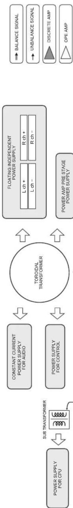
Large power supply with four separate circuits
Left-right symmetrical design
Fully discrete phono amp
Low-impedance, high-performance headphone amp
Things to know before using this product
About this manual
- This manual describes the unit's features and connection procedures.
- The illustrations as shown in this manual are for instructional purposes only.
- Specifications and appearance are subject to change without notice.
WARNING" describes precautions to be followed to avoid the possibility of serious injury or even death.
CAUTION" describes precautions to be followed to avoid injury.
- "NOTICE" describes precautions to be followed to avoid malfunction or damage to the product.
- " deNotes supplemental information about the product.
Supplied accessories
Please make sure that the following accessories are included in the package.
- Remote control
- Batteries (AAA, R03, UM-4) (× 2)
- Power cable*
- Owner's Manual (this book)
-
Safety Brochure
-
Multiple power cables might be included in the package depending on the area of distribution. Please use the one that is appropriate for your AC outlet.
Table of Contents
Features. 3
Things to know before using this product.. 4
About this manual. 4
Supplied accessories. 4
Part Names and Functions 5
Front panel. 6
Rear panel 10
Remote control. 12 Installing batteries in the remote control... 14
Operating the remote control. 14
Connections 15
Connection diagram 16
Connecting speakers 18
Using speaker cables 18
Using banana plug cables. 19
Using Y-shaped lug cables. 19
Bi-wired connection 19
Balanced connection. 20
Trigger connection 20
Remote connection. 21
Operating the unit from another room....21
Remote connection between
Yamaha components. 21
Connecting the power cable. 22
Appendix. 23
Specifications. 24
Block diagram. 26
Acoustic characteristics. 27
Tone control characteristics 27
Total harmonic distortion 27
Total harmonic distortion (PHONO) 28
Troubleshooting 29
Maintenance. 30
Part Names and Functions
This section lists the names and describes the function of various parts on the front and rear panels, and the remote control.
Part Names and Functions
Front panel
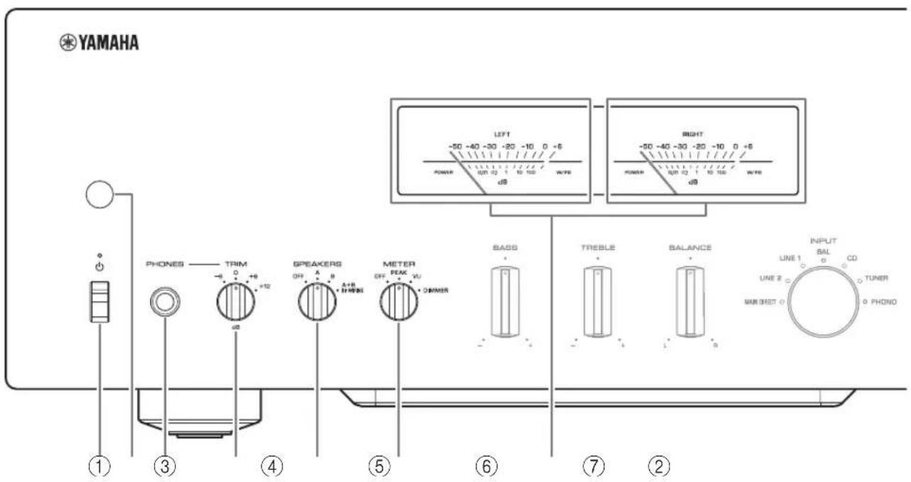
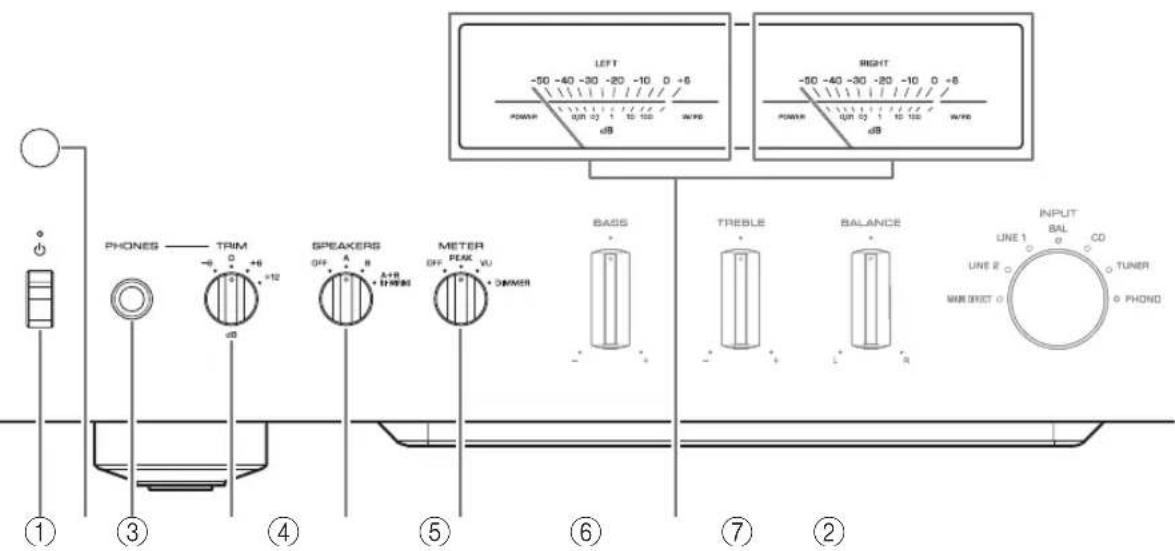
(Power) switch/indicator
| ( Power ) switch | Power status Indicator | |
| Up position | On Lit brightly | |
| Standby Lit dimly | ||
| Down position Off | Off | |
While the (Power) switch is in the up position, press the AMP key on the remote control repeatedly to switch the power to the unit between on and standby mode. In addition, under either of the following conditions, the unit will enter standby mode.
If the Auto Power Standby function is enabled. ( page 10)
- If you turn off the power to a device that has been set to trigger connection to this unit. ( page 20)
NOTICE
If you plan not to use the unit for an extended period of time, be sure to unplug the power plug from the AC outlet. Even when the power is turned off, a minimal amount of electric current is still flowing to the unit.
Note
After you turn on the unit, it will take a few seconds before the unit can reproduce sound.
- Do not turn on the power to this unit again within 10 seconds after the power has been turned off. Doing so may generate noise.
- While the unit is in standby mode, to turn on power to the unit first set the (Power) switch to the down position to turn the power off, then set the switch to the up position.
- While the unit is in standby mode, if you unplug the power cable from the AC outlet and then plug it in again, the power to the unit will be turned on.
② Remote control sensor
Receives signals from the remote control. ( page 14)
③PHONES jack
Connect your headphones here.
Note
- Connecting the headphones here will result in the following:
- No sound will be heard from the connected speakers.
- Audio signals will not be output at the PRE OUT jacks.
- You will be unable to select MAIN DIRECT as the input source.
- If MAIN DIRECT is selected as the input source, audio signals will not be output at the PHONES jack.
④TRIM selector
Switches the headphone amp gain.
Select the gain setting that is appropriate for your headphones.
Available gain:
-6dB,0dB,+6dB,+12dB
⑤SPEAKERS selector
Switches sets of speakers connected to the SPEAKERS L/R CH A and B terminals on the rear panel as follows:
OFF: No audio signals will be output from the speakers.
A: Audio signals will be output from the set of speakers connected to the A terminals.
B: Audio signals will be output from the set of speakers connected to the B terminals.
A+B BI-WIRING: Audio signals will be output from the sets of speakers connected to the A and B terminals. Select this position when you plan to make a bi-wired connection. ( page 19)
NOTICE
[Model for Asia]
If you connect two sets of speakers (A + B) , use the speakers with an impedance of 12 or higher.
[Other models]
If you connect two sets of speakers (A + B) , use the speakers with an impedance of 8 or higher.
⑥METER selector
Switches the meter function as follows:
OFF: Turns off meter operation and display illumination.
PEAK: Switches the meter display type to a peak level meter. The peak level meter shows the highest instantaneous level of an audio output signal.
VU: Switches the meter display type to a VU (Volume Unit) level meter. The VU level meter shows an effective audio output value that represents the way sound is perceived by human ears.
DIMMER: When selected, the DIMMER automatically changes the brightness of the meter display in steps. When you see the brightness level you desire, switch to another setting parameter to lock in the new brightness setting.
⑦Meter (LEFT/RIGHT)
Indicates the audio output level of the left (LEFT) and right (RIGHT) channels.
Part Names and Functions
Front panel
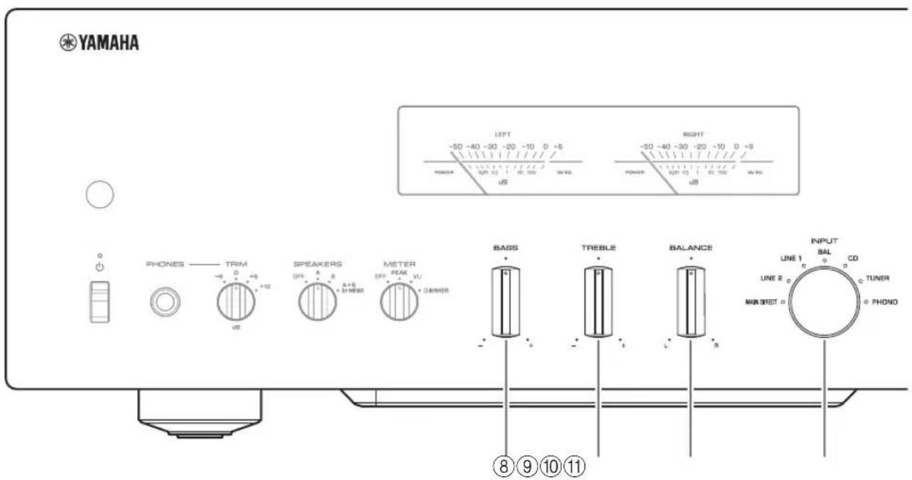
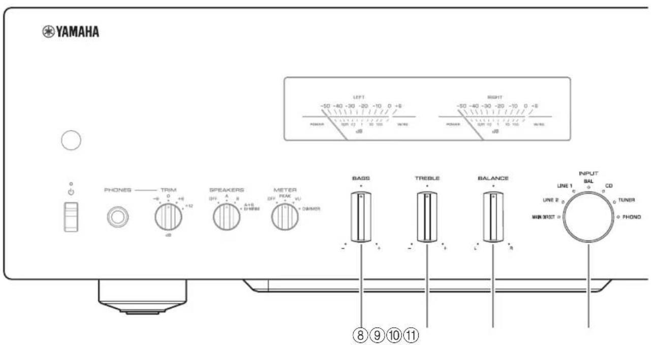
BASS control
Adjusts the volume level of the bass range.
Adjustable range: -10dB - 0 + 10dB
⑨TREBLE control
Adjusts the volume level of the treble range.
Adjustable range: -10dB - 0 + + 10dB
10BALANCE control
Adjusts the audio output balance between the left and right speakers to compensate for sound imbalances caused by speaker locations or listening room conditions.
Note
- If both BASS and TREBLE controls are set to 0 (zero), the audio signal will bypass the tone control circuit.
- The BASS, TREBLE, and BALANCE control settings will not affect the input signals at the MAIN IN jacks nor the output signals at the LINE 2 OUT jacks.
⑪INPUT selector/indicator
Selects the input source. The indicator for the selected input source lights up. Audio signals of the selected input source will be output at the LINE 2 OUT jacks.
MAIN DIRECT: Selects the component connected to the MAIN IN jacks as the input source.
LINE 1/LINE 2: Selects the component connected to the LINE 1 or LINE 2 jacks as the input source.
BAL: Selects the component connected to the BAL input jacks as the input source.
CD: Selects the CD player connected to the CD input jacks as the input source.
TUNER: Selects the tuncr connected to the TUNER input jacks as the input source.
PHONO: Selects the turntable connected to the PHONO input jacks as the input source.
Note
- If MAIN DIRECT is selected as the input source, audio signals will not be output at the PRE OUT, LINE 2 OUT or PHONES jacks.
- If LINE 2 is selected, audio signals will not be output at the LINE 2 OUT jacks.
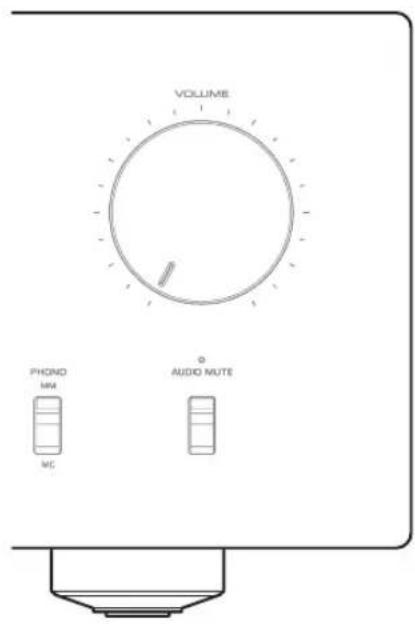
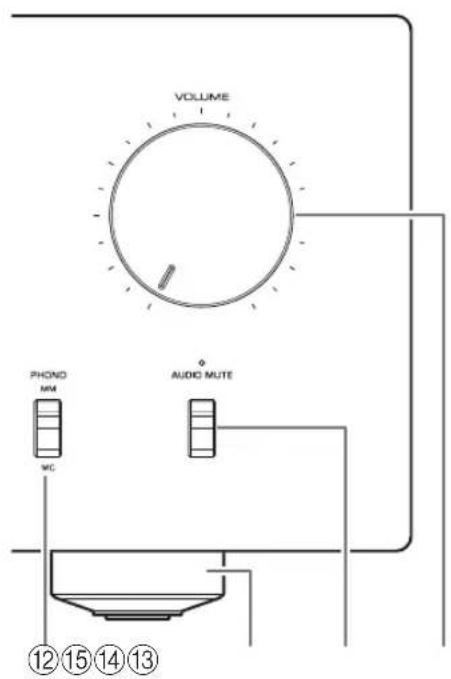
⑫PHONO switch
Set this switch to the MM or MC position according to the type of magnetic cartridge of the turntable connected to the PHONO input jacks on the rear panel.
Note
Before you replace the cartridge for the turntable, be sure to turn off the power to this unit.
13Feet
If the unit is unstable, adjust the height of the feet as needed by rotating them.
14 AUDIO MUTE switch/indicator
Press this switch to reduce the current volume level by approximately 20 dB. The indicator will light up. Press again to restore the audio output to the previous volume level. The indicator will turn off.
15VOLUME knob
Adjusts the volume level. This setting will not affect the output level at the LINE 2 OUT jacks.
NOTICE
If you select MAIN DIRECT as the input source for this unit, the volume level will be fixed. In this case, to adjust the volume level, use the volume control on the external amplifier connected to the MAIN IN jacks.
Part Names and Functions
Rear panel
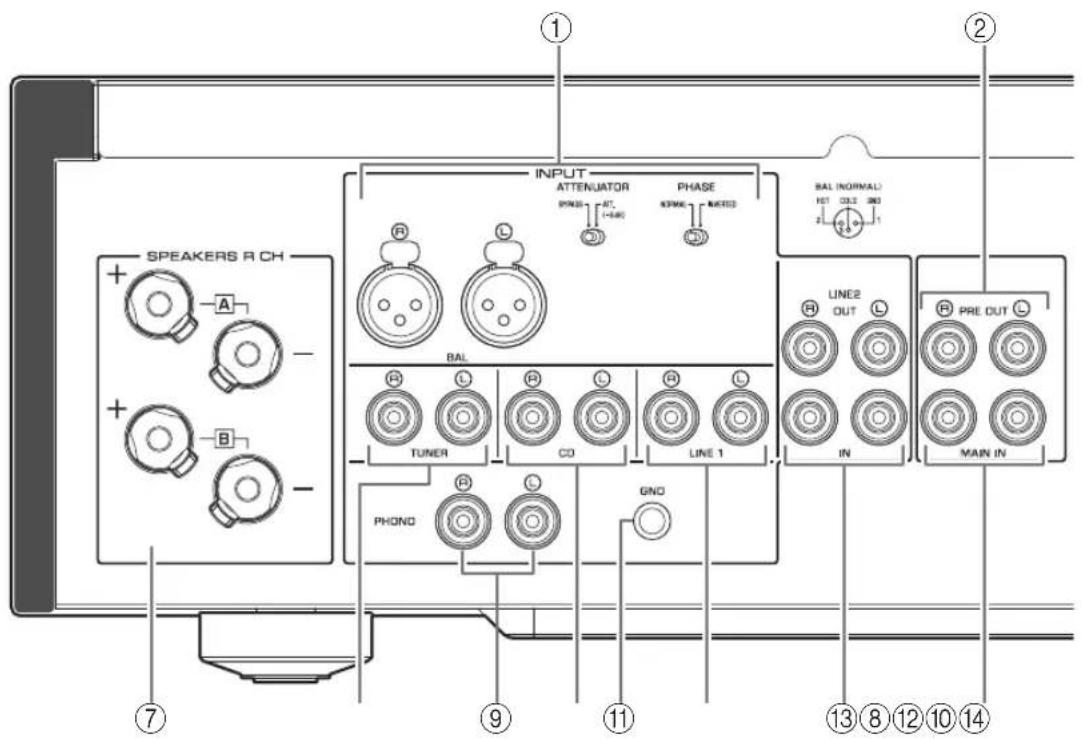
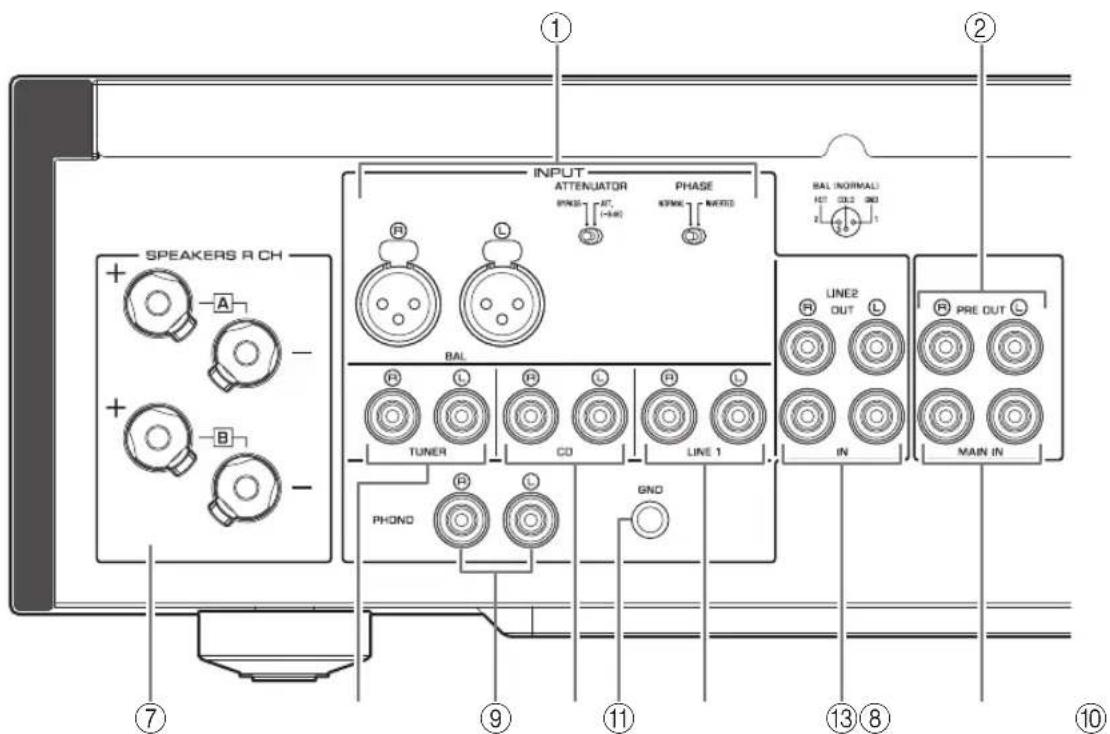
① BAL (balanced) input jacks
Note
Set the ATTENUATOR selector and PHASE selector appropriately for the playback component that is connected to these jacks. ( page 20)
PRE OUT jacks
Note
- Audio signals output at the PRE OUT jacks are the same channel signals that are output at the SPEAKERS L/R CH terminals.
The following parameter settings are effective for audio signals output at the PRE OUT jacks.
-BASS
-TREBLE
-BALANCE
VOLUME
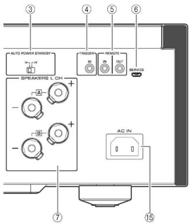
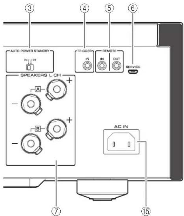
③ AUTO POWER STANDBY switch
ON: The unit enters standby mode automatically if it is left turned on and not operated for eight hours (Auto Power Standby function).
OFF: The unit does not enter standby mode automatically.
④TRIGGER IN jack
Connect external components that support the trigger function. ( page 20)
⑤REMOTE IN/OUT jacks
Connect external components that support the remote function. ( page 21)
⑥ SERVICE jack
This jack is used to test the product.
⑦SPEAKERS L/R CH terminals
8TUNER input jacks
⑨PHONO input jacks
CD input jacks
① GND (Ground) terminal
If you connect your turntable to this unit, ground it to the GND terminal. Doing so may reduce noise.

CAUTION
Do not loosen the GND terminal knob excessively. Otherwise, the knob may come off and a child may swallow it accidentally.
Note
This is not a safety ground.
LINE 1 input jacks
LINE 2 jacks
Connect external components that feature analog audio in/out jacks.
14MAIN IN jacks
Connect external components that feature a volume control function so that you can use this unit as a power amplifier.
NOTICE
If you select MAIN DIRECT as the input source for this unit, the volume level will be fixed. In this case, to adjust the volume level, use the volume control on the external amplifier connected to the MAIN IN jacks.
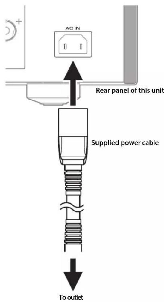
15AC IN jack
Connect the supplied power cable here. ( page 22)
Part Names and Functions
Remote control
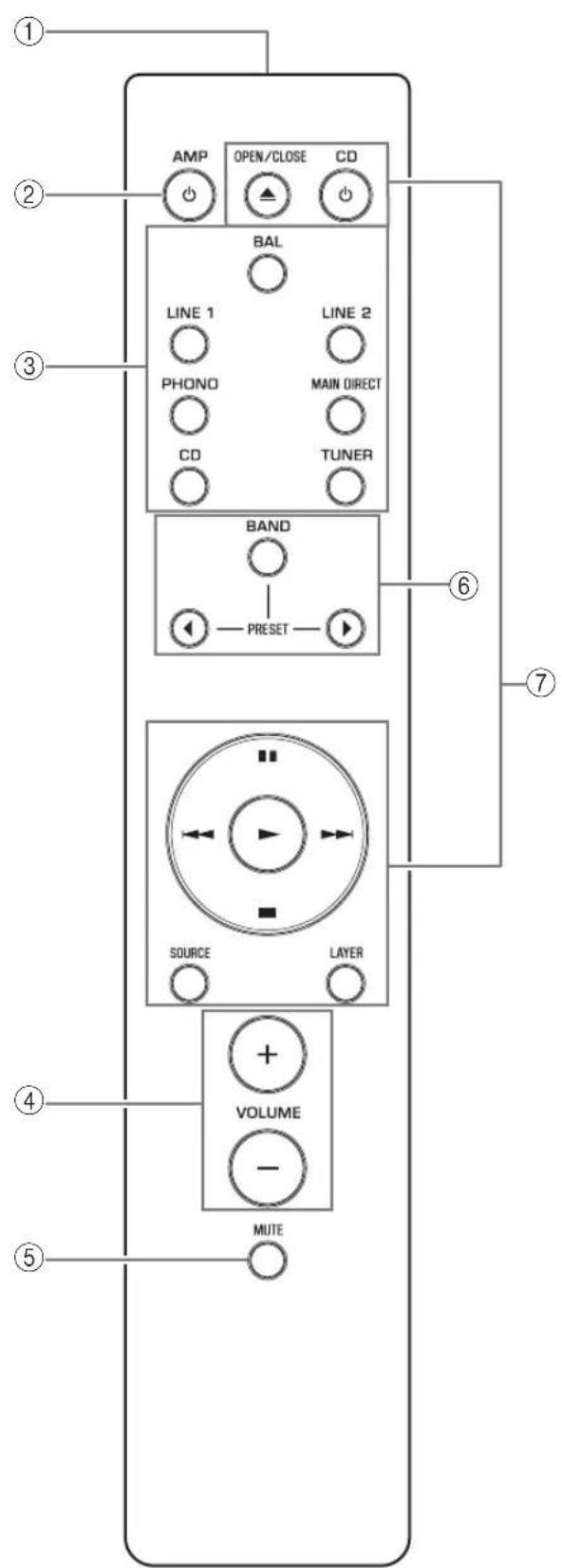
① Infrared signal transmitter
Outputs infrared control signals toward the unit. ( page 14)
② AMP key
Turns on the power to the unit or switches it to standby mode. () page 6
③Input select keys
Select the input source.
Audio signals of the selected input source will be output at the LINE 2 OUT jacks.
BAL: Selects the component connected to the BAL input jacks as the input source.
LINE 1/LINE 2: Selects the component connected to the LINE 1 or LINE 2 jacks as the input source.
PHONO: Selects the turntable connected to the PHONO input jacks as the input source.
MAIN DIRECT: Selects the component connected to the MAIN IN jacks as the input source.
CD: Selects the CD player connected to the CD input jacks as the input source.
TUNER: Selects the tuner connected to the TUNER input jacks as the input source.
Note
- If MAIN DIRECT is selected as the input source, audio signals will not be output at the PRE OUT, LINE 2 OUT or PHONES jacks.
- If LINE 2 is selected, audio signals will not be output at the LINE 2 OUT jacks.
④VOLUME+/-keys
Adjust the volume level. This setting will not affect the output level at the LINE 2 OUT jacks.
NOTICE
If you select MAIN DIRECT as the input source for this unit, the volume level will be fixed. In this case, to adjust the volume level, use the volume control on the external amplifier connected to the MAIN IN jacks.
⑤MUTEkey
Press this key to reduce the current volume level by approximately 20 dB. Press the key again to restore the previous volume level.
⑥ Tuner control keys
Control the functions of a connected Yamaha tuner. For more information, refer to the owner's manual for your tuner.
CD player control keys
Control the functions of a connected Yamaha CD player. For more information, refer to the owner's manual for your CD player.

OPEN/CLOSE key: Opens or closes the disc tray of a connected CD player.
CD key: Turns on the power to a connected CD player, or switches it to standby mode.
▶ (Play): Starts playback of the CD player.
(Pause): Pauses playback of the CD player. Press or tunsume playback.
(Stop): Stops playback of the CD player.
/ (Skip): Skips to the next track, or returns to the beginning of the current track.
SOURCE key: Selects the source to be played on the CD player. The playback source changes each time this key is pressed.
LAYER key: Toggles the playback layer of a hybrid super audio CD between "Super audio CD" and "CD."
Note
Some Yamaha tuners or CD players might not support the tuner or CD player control keys.
Part Names and Functions
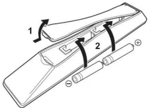
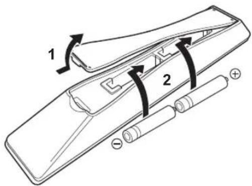
■Installing batteries in the remote control
1Remove the battery compartment cover.
2 Insert two batteries (AAA, R03, UM-4) according to the polarity markings (+ and -) on the inside of the battery compartment.
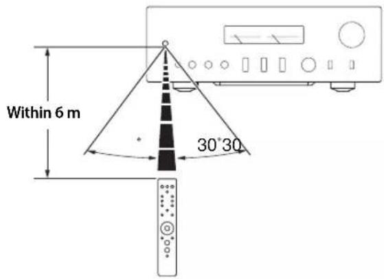
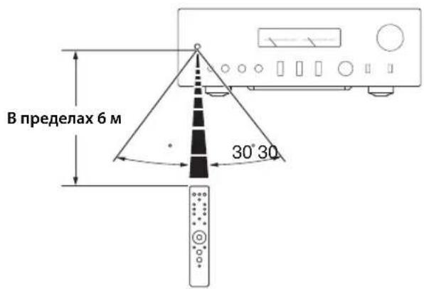
Operating the remote control
Operate the remote control in the range shown below by pointing it toward the remote control sensor on the front panel of the unit.
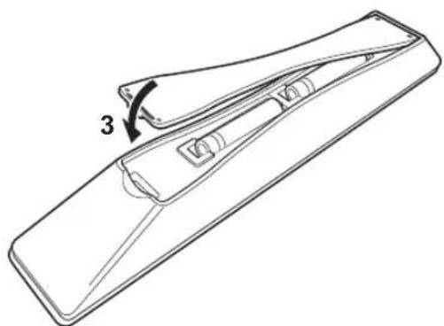
3Reinstall the battery compartment cover.

Connections
This section explains how to connect the unit to speakers and audio source components.
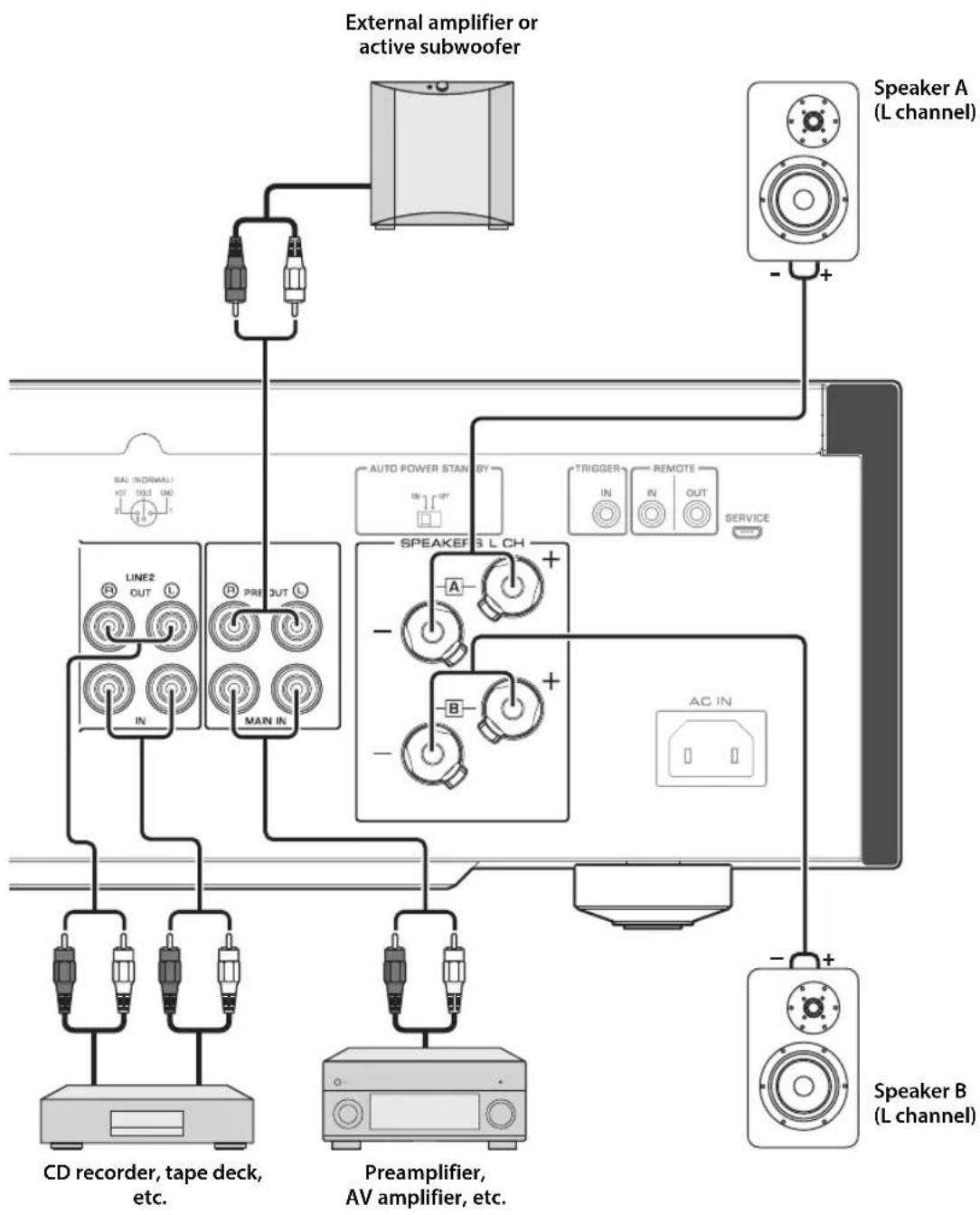
Connections
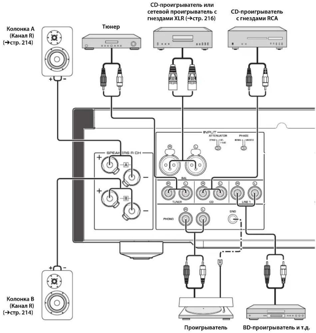
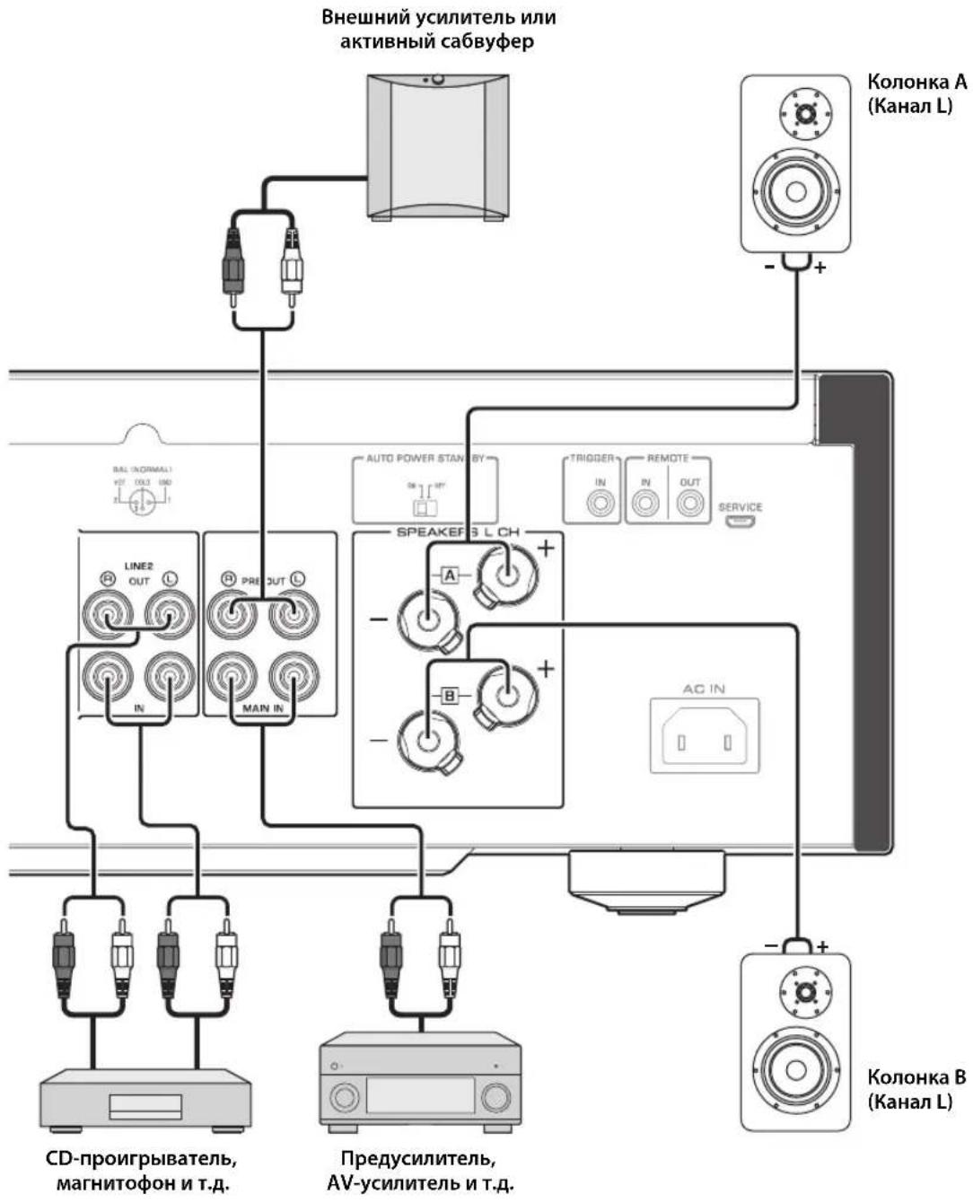
Connection diagram

CAUTION
Be sure to complete all connections before plugging in the power cable to an AC outlet. ( page 22)
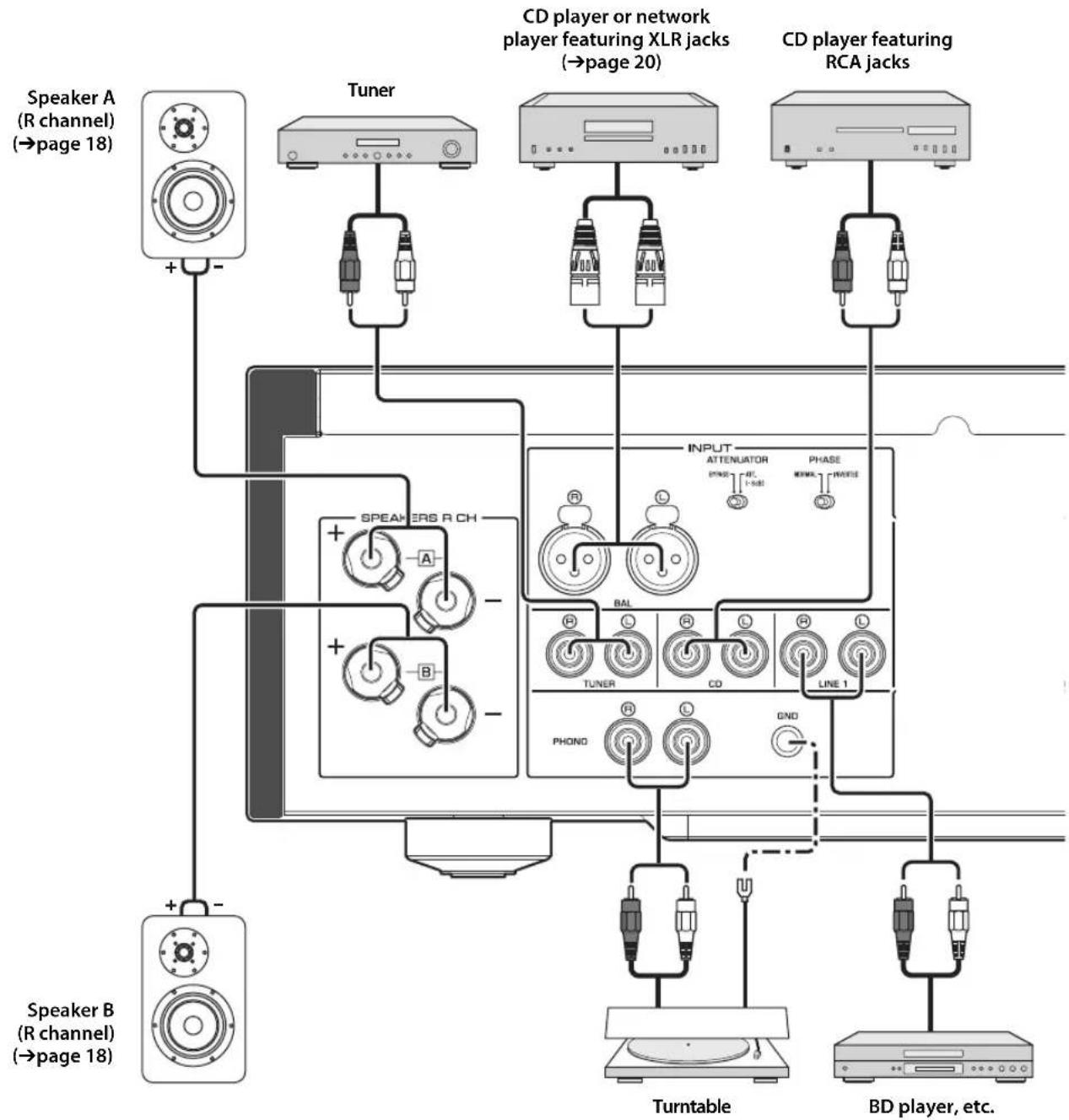
NOTICE
If a component is connected to the MAIN IN jacks, the unit's volume level will be fixed. Therefore, do not connect a CD player or other components that do not feature volume adjustment to the MAIN IN jacks. Otherwise, a loud sound may be emitted, resulting in malfunction of the unit or damage to the speakers.
Connecting speakers
Note
-
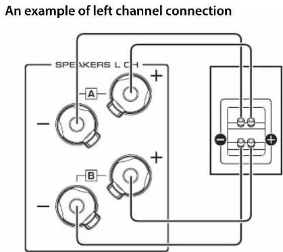
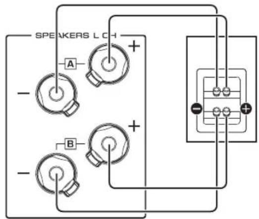
Because this power amplifier is of the floating balanced type, the following connections are not possible.
-
Connecting between two "+" (or two "-" terminals of the left and right channels (Fig. 1).
- Connecting each "--" terminal of the unit's left and right channels to the opposite channel speakers (cross connection, Fig. 2).
- Connecting the left/right channel " - " terminals (or accidentally allowing them to come in contact) with the metal part of the rear panel of this unit.
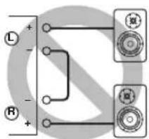
Figure 1
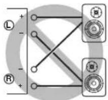
Figure 2
- Do not connect an active subwoofer to the SPEAKERS L/R CH terminals. Connect the subwoofer to the unit's PRE OUT jacks.
Using speaker cables
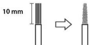
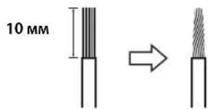
1 Remove approximately 10mm of insulation from the end of each speaker cable, and twist the exposed wires together tightly to prevent short circuits.
2Unscrew the knob on each speaker terminal, and then insert the bare wire into the side hole on the terminal.
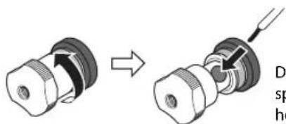
Diameter of the speaker cable wire hole: 6.0mm
3Tighten the knob.

CAUTION
- Do not loosen the knob excessively. Otherwise, the knob may come off and a child may swallow it accidentally.
To reduce the risk of electric shock, do not touch the speaker terminals while the power to the unit on.
NOTICE
- If the SPEAKERS terminals come into contact with a metallic rack, a short circuit may occur, resulting in damage to this unit. When installing the unit in a rack, maintain a sufficient clearance to prevent the SPEAKERS terminals from coming into contact with the rack.
- Do not let the bare speaker wires touch each other, nor let them touch any metal part of this unit. Otherwise, the unit and/or the speakers may be damaged.
Note
All connections must be correct: L (left) to L, R (right) to R, "+" to "+" and "-" to "-" For information regarding the connection procedure, refer to the owner's manual for your speakers.
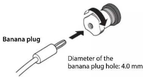
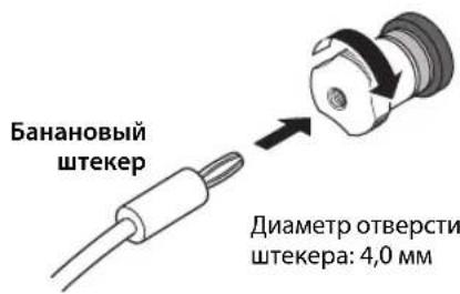
Using banana plug cables
(Models for U.S.A., Canada, Australia, China, and Taiwan)
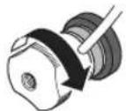
First tighten the knob on the SPEAKERS terminal, and then insert the banana plug into the head of the knob.
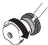
Using Y-shaped lug cables
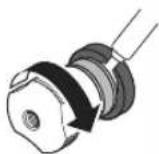
1Unscrew the knob, and then sandwich the Y-shaped lug between the ring part and base of the terminal.
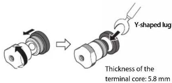
2Tighten the knob.
Bi-wired connection
A bi-wired connection separates the woofer from the mid and high ranges. Speakers that support bi-wired connection feature two pairs of terminals (total four terminals). These two pairs of terminals can divide the speakers into two independent parts. To make this kind of connection, you need to connect mid and high range drivers to one pair of terminals, and low range drivers to the other pair of terminals.
1 Remove the shorting bars or bridges on the speakers.
2Connect this unit to the speakers as shown in the figure below.
Rear panel of this unit Speaker
3Set the SPEAKERS selector on the front panel to A+B BI-WIRING.
Connections
Balanced connection
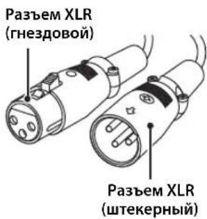
You can connect a CD player or network player that features XLR-type balanced output jacks to the BAL input jacks of this unit. Use XLR-type balanced cables for this connection.
ATTENUATOR selector: Enables you to set the allowable input level at the balanced input jacks. Select ATT. (-6dB) if the audio output from the connected component sounds distorted.
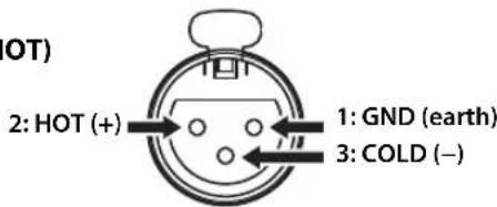
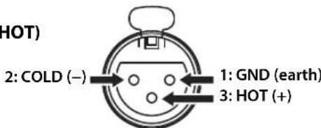
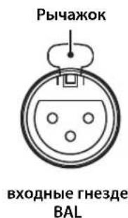
PHASE selector: Enables you to set the position (phase) of the HOT pin (pin #2: HOT or pin #3: HOT) at the balanced input jacks.
NORMAL
(Pin #2: HOT)
INV.
(Pin #3: HOT)
Refer to the instruction manual for the connected component to find out the position of the HOT pin at the balanced output jacks on the component.
Note
- Select NORMAL (pin #2 is HOT) for a Yamaha player.
- Do not use balanced and unbalanced connections for one component simultaneously. Doing so would create a ground loop that could generate static and noise.
- When connecting a cable, be sure to align the pins on the connector with the holes on the jack, and then insert the male XLR connector into the jack until you hear a click. To remove the cable, while pressing and holding down the lever on the BAL input jack, pull out the male XLR connector from the jack.
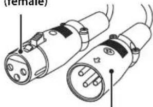
XLR connector (female)
XLR connector (male)
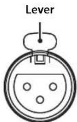
BAL input jack
- For a balanced connection, select BAL as the input source.
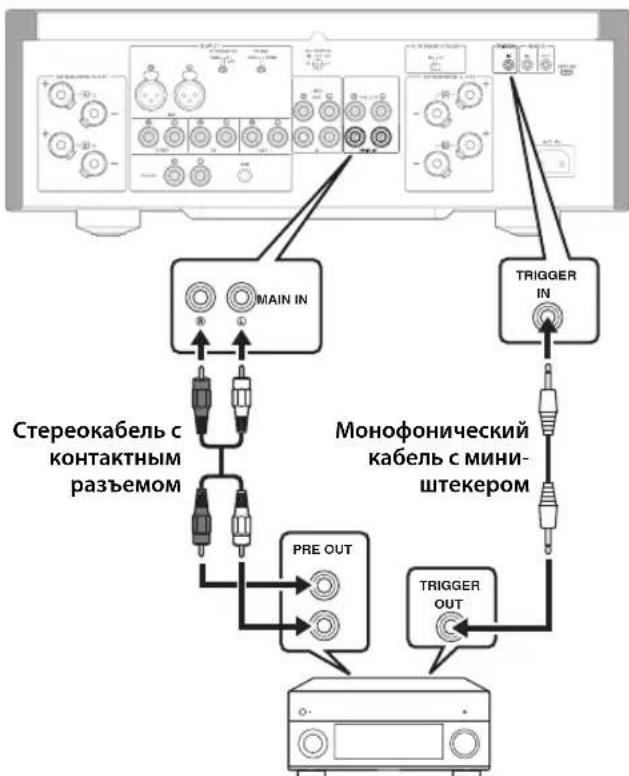
Trigger connection
You can connect a Yamaha AV receiver or other component that supports the Trigger function. You can control this unit in sync with a connected component.
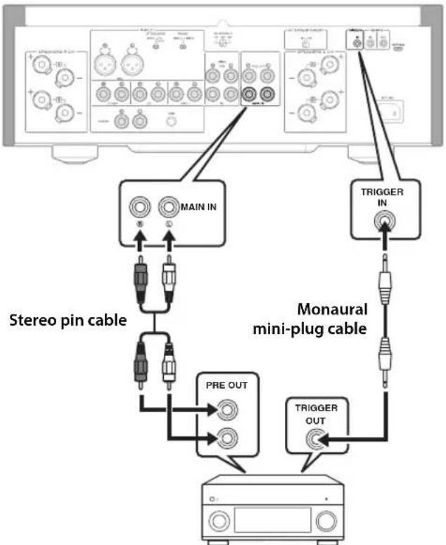
Rear panel of this unit
Yamaha AV receiver or other component that features TRIGGER OUT jacks and PRE OUT jacks
When the power to the connected component is turned on, the power to this unit is also turned on. Simultaneously, the input source to the unit is set to MAIN DIRECT.
If MAIN DIRECT has been selected as the input source for this unit, when the power to the connected component is turned off, this unit will enter standby mode.
Note
When the power switch on this unit is turned Off, the power to the unit will not be triggered.
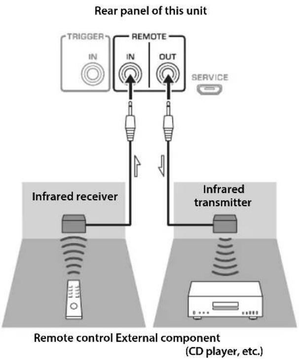
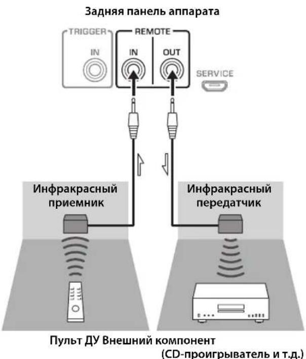
Remote connection
■Operating the unit from another room
If you connect a commercially-available infrared receiver and transmitter to the unit's REMOTE IN/OUT jacks, you will be able to operate the unit and/or external component from another room, using the supplied remote control.
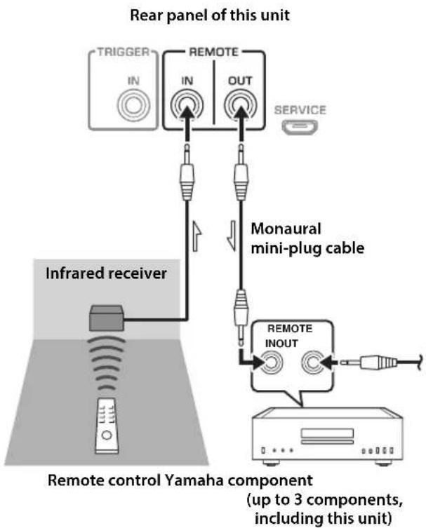
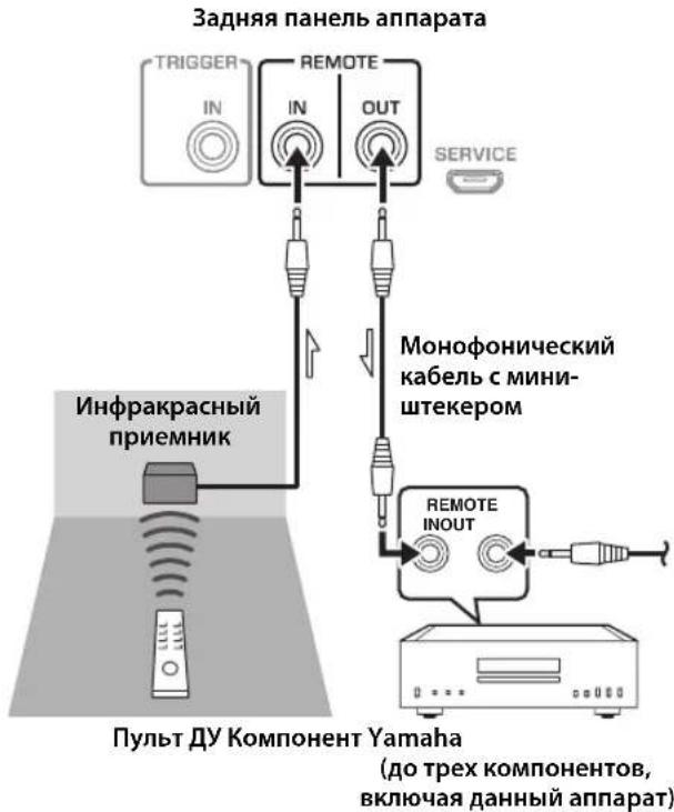
Remote connection between Yamaha components
If you have another Yamaha component that supports remote connections, an infrared transmitter is not necessary. Connect an infrared receiver to the unit's REMOTE IN/OUT jacks, as shown below.
Up to 3 Yamaha components (including this unit) can be set up for remote connection.
Connections
Connecting the power cable
After all connections are complete, plug the power cable into the AC IN connector of the unit, and then plug the power plug into the AC outlet.
Appendix
This section lists technical specifications for this unit.
C
Channel separation (JEITA, 1 kHz/10 kHz)
PHONO (MC) 66/77 dB or higher
PHONO (MM) 90/77 dB or higher
CD (or similar)/BAL. 74/54 dB or higher
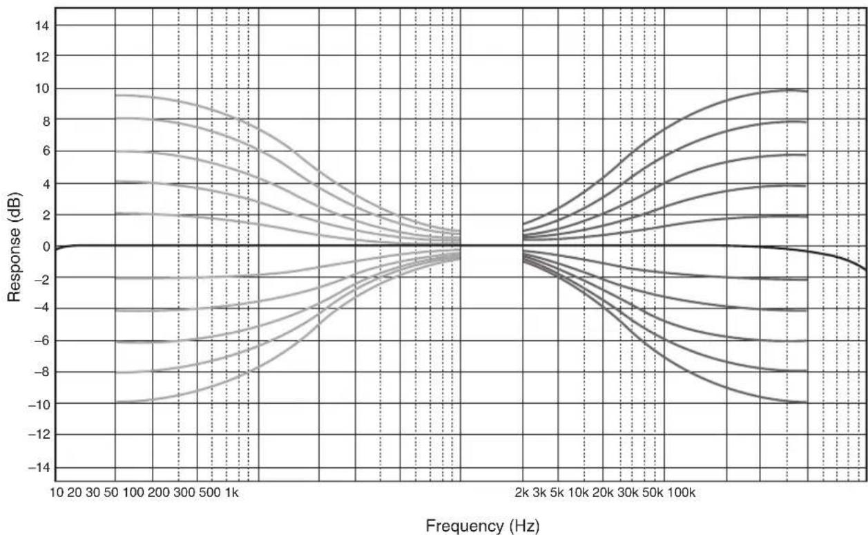
Tone control characteristics
BASS
Boost/cut 50 Hz / ±9 dB
Turnover frequency. 350 Hz
TREBLE
Boost/cut 20 kHz/±9 dB
Turnover frequency. 3.5 kHz
Power supply
[Models for U.S.A. and Canada] ... AC 120 V, 60 Hz
[Model for China] AC 220 V, 50 Hz
[Model for Korea]AC 220 V,60 Hz
[Model for Australia]AC 240 V,50 Hz
[Models for U.K. and Europe]AC 230 V,50 Hz
[Model for Asia] AC 220-240 V, 50 Hz/60 Hz
[Model for Taiwan]AC 110 V, 60 Hz
Power consumption
[Model for Asia] 250 W
[Other models] 350 W
Standby power consumption
OFF mode 0.1 W
Standby mode 0.2 W
Maximum power consumption (1 kHz, 4Ω 10% THD)
[Model for Taiwan] 700 W
Dimensions (W× H× D)
435× 157× 463mm
Weight
22.7 kg
- The contents of this manual apply to the latest specifications as of the publishing date. To obtain the latest manual, access the Yamaha website and download the manual file.
O
Acoustic characteristics
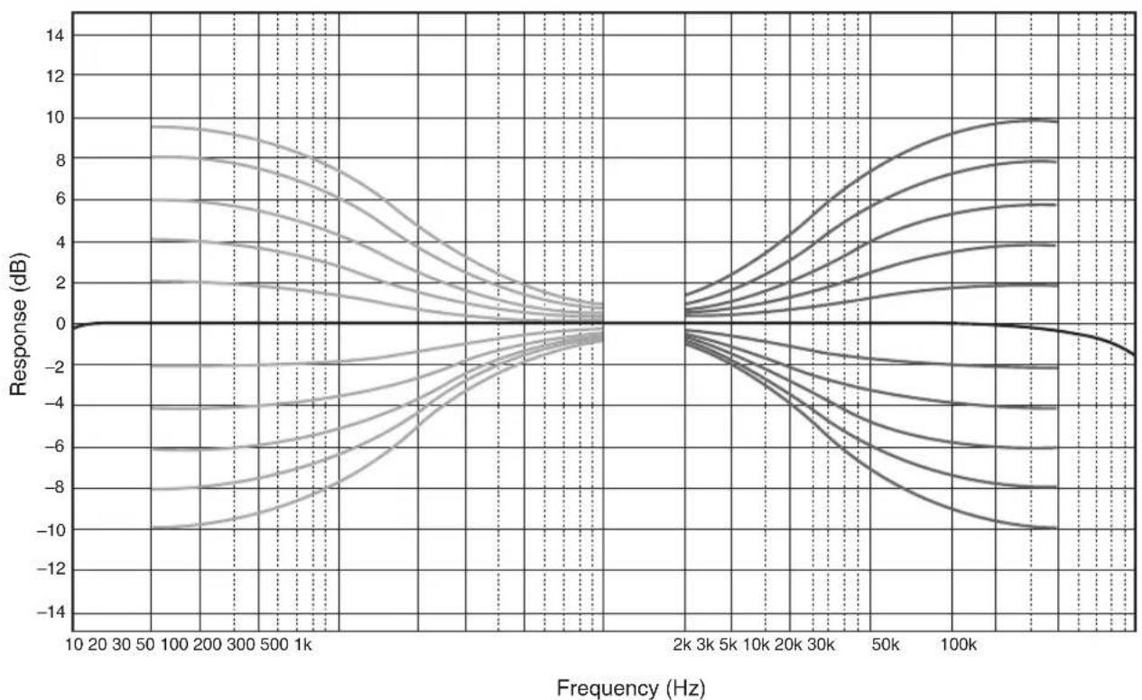
■Tone control characteristics
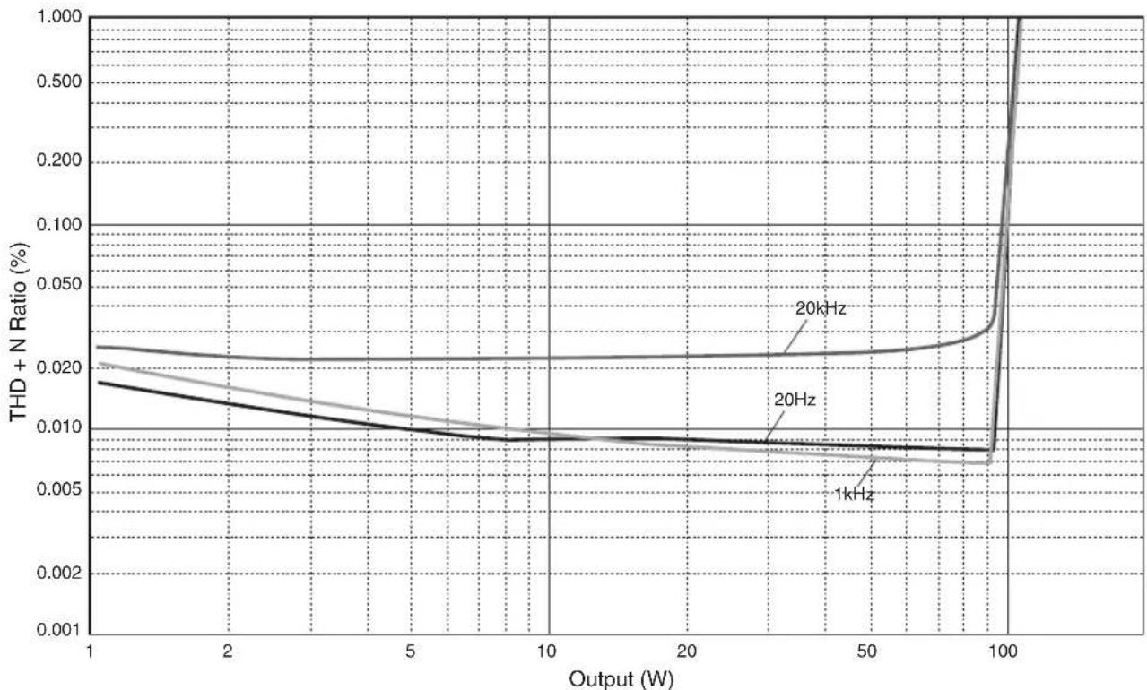
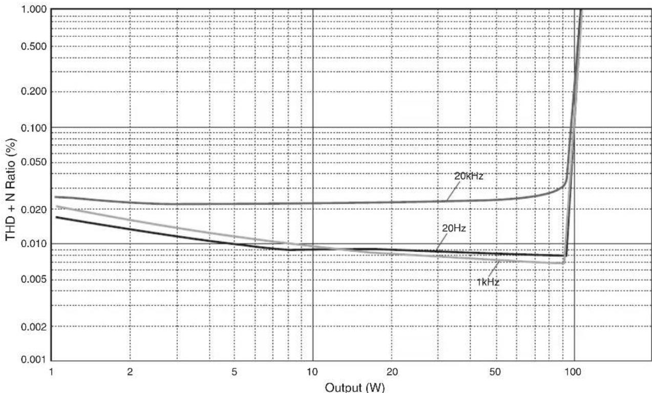
Total harmonic distortion
Appendix
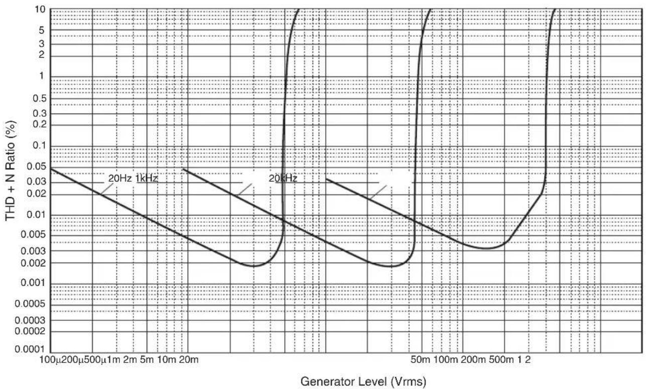
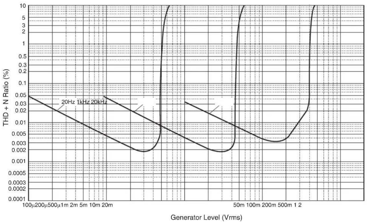
Total harmonic distortion (PHONO)
Troubleshooting
Refer to the table below if this unit does not function properly. If the instructions below do not help, or if the problem you are experiencing is not listed below, turn off the unit, disconnect the power plug, and contact the nearest authorized Yamaha dealer or service center.
| Problem Cause Remedy | See page | ||
| Power does not turn on. | The power cable is not connected to the AC IN connector on the rear panel or is not plugged into an AC outlet. | Connect the power cable firmly. 22 | |
| The unit has been exposed to a strong external electric shock (such as lightning or strong static electricity). | Turn off the unit, disconnect the power plug from the AC outlet, wait for about 30 seconds, and then plug the unit in again. | — | |
| The (Power) indicator on the front panel flashes. | The protection circuitry has been activated because of a short circuit, etc. | Make sure that the speaker wires are not touching each other or shorting out against the rear panel of the unit, and then turn on the power to the unit. | 18 |
| There is a problem with the internal circuitries of this unit. | Disconnect the power plug from the AC outlet and contact the nearest authorized Yamaha dealer or service. | — | |
| When the unit is powered on, the INPUT indicator flashes and the volume level decreases. | The protection circuitry has been activated because of a short circuit, etc. | Make sure that the speaker wires are not touching each other or shorting out against the rear panel of the unit, and then turn on the power to the unit. | 18 |
| No sound is heard. | Incorrect input or output cable connections. | Connect the cables properly. If the problem persists, the cables might be defective. | 16 |
| No appropriate input source has been selected. | Select an appropriate input source using the INPUT selector on the front panel (or one of the input selector keys on the remote control). | 8, 12 | |
| The SPEAKERS selector is set to OFF. | Set the SPEAKERS selector to the appropriate position. | 7 | |
| The speaker cables are not connected properly. | Make sure that the speaker cables are connected properly. | 18 | |
| The sound is suddenly muted. | The protection circuitry has been activated because of a short circuit, etc. | Make sure that the speaker wires are not touching each other or shorting out against the rear panel of the unit, and then turn on the power to the unit. | 18 |
| The volume level cannot be adjusted. | MAIN DIRECT is selected as the input source. | Adjust the volume level on the connected component. Alternatively, connect the external component to a pair of the input jacks other than the MAIN IN jacks, and then select the corresponding input source. | 8 |
| Only one channel speaker can be heard. | The playback component or speakers are not connected properly. | Make sure that they are connected properly. If the problem persists, the cables might be defective. | 16 |
| The volume level balance between the left and right speakers is not adjusted properly. | Adjust the volume level balance between the left and right speakers properly using the BALANCE control. | 8 | |
| Problem Cause Remedy | See page | ||
| There is a lack of bass and no ambience. | The + and - wires are connected in reverse at the amplifier or the speakers. | Connect the speaker wires to the correct + and - phase. | 18 |
| A "humming" noise is heard. | Incorrect input or output cable connections. | Connect the cables properly. If the problem persists, the cables might be defective. | 16 |
| The turntable is not grounded to the GND terminal. | Connect the turntable to the GND terminal of this unit. | 16 | |
| Playback audio from the component connected to the BAL input jacks sounds distorted. | The level of the signal at the balanced input jacks is exceeding the allowable input level. | If the level of the signal at the XLR-type balanced output jacks on the connected playback component is doubled compared to the RCA unbalanced jacks, set the ATTENUATOR selector located below the input jacks to ATT. (-6 dB). | 20 |
| Bass lacks depth when BAL is selected. | The polarity is incorrect. | Select the correct polarity using the PHASE selector. | 20 |
| Playback audio is distorted while you listen to a connected CD player or tape deck through headphones (that are connected to a CD player or tape deck). | The power to the unit is turned off. Turn | on the power to the unit. 6 | |
| The volume level of the vinyl record is too low. | The PHONO switch on the front panel is set incorrectly. | Set the PHONO switch to the MM or MC position according to the type of magnetic cartridge of the turntable. | 9 |
| The remote control does not work or function properly. | The remote control has been used out of the operating range. | The remote control must be used within a maximum distance of 6 m and no more than 30 degrees off-axis from the remote control sensor on the front panel. | 14 |
| Direct sunlight or lighting (from an inverter type of fluorescent lamp, strobe light, etc.) is hitting the remote control sensor on the front panel. | Change the orientation of the lighting or reposition the unit. | - | |
| The batteries are weak. Replace all batteries. 14 | |||
Maintenance
Mirror-finish side panels
We recommend that you use a cleaning cloth such as those made for pianos.
Other surfaces
Do not use chemical agents, such as benzene or thinner for cleaning. Otherwise, the surfaces might be damaged. Wipe the surfaces using a soft dry cloth.
⑤Prises REMOTE IN/OUT
Accentuation/attenuation 50 Hz / ±9 dB
Accentuation/attenuation 20 kHz / ±9 dB
Consummation maximum (1 kHz, 4Ω, DHT 10%)
(JEITA, 1 kHz, 10% THD)
8Ω 120W+120W
4Ω 190W+190W
MAIN IN 1 Vrms/47 kΩ
BAL. 200 mVrms / 100 kΩ
PIIONO (MC) 2,0 mVrms
PIIONO (MM) 50 mVrms
CD (o.A.) 2,80 Vrms
BAL
BYPASS. 2,80 Vrms
ATT. (-6 dB). 5,60 Vrms
Bi-wired anslutning 103
⑤REMOTE IN/OUT-uttag
Anslut externakomponenter som stoder den fjarrstyrdafunktionen. ( sidan 105)
⑥SERVICE-uttag
(JEITA, 1 kHz, 10% THD)
8Ω 120W+120W
4Ω 190W+190W
Effektbandbredd (0,1% THD, 45 W)
2-kanalsdriven
8Ω 10 Hz till 50 kHz
Dämpningsfaktor (1 kHz)
8Ω 250 ether hogre
MAIN IN .1 Vrms/47 kΩ
BAL 200 mVrms / 100 kΩ
Maximal signalspanning vid ingang (1 kHz, 0,5% THD)
PHONO (MC) 2,0 mVrms
PHONO (MM). 50 mVrms
CD (eller liknande) 2,80 Vrms
BAL
BYPASS. 2,80 Vrms
ATT. (-6 dB). 5,60 Vrms
[Modell for Taiwan] 700 W
Matten (B× H× D)
435× 157× 463mm
Vikt
22,7 kg
Collegamento bi-wire 131
⑤Prese REMOTE IN/OUT
Collegamento bi-wire
MAIN IN 1 Vrms/47 kΩ
BAL. 200 mVrms / 100 kΩ
PHIONO (MC) 2,0 mVrms
PHIONO (MM) 50 mVrms
CD (o simile) 2,80 Vrms
BAL
BYPASS. 2,80 Vrms
ATT. (-6 dB). 5,60 Vrms
Rumore residuo (rete IHF-A)
33 Vrms
Consumo energetico in standby
⑤Tomas REMOTE IN/OUT
MAIN IN 1 Vrms/47 kΩ
BAL. 200 mVrms / 100 kΩ
PHIONO (MC) 2,0 mVrms
PHONO (MM). 50 mVrms
CD (o similar). 2,80 Vrms
BAL
BYPASS. 2,80 Vrms
ATT. (-6 dB). 5,60 Vrms
(JEITA, 1 kHz, 10% THD)
8Ω 120W+120W
4Ω 190W+190W
Vermogensbandbreedte (0,1%) THD, 45 W
PHIONO (MC) 2,0 mVrms
PHONO (MM). 50 mVrms
PHONO (MC) 66/77 dB of hoger
PHONO (MM) 90/77 dB of hoger
BHUMAHNE 063Haet MepbI IpeIOCTOpOxHocTH, KOTOpBc CJeYeT COJHOaTb, TTObI H36ekaTb
pHcKa TpaBmbl.
- YBEOMJIeHHe 6o3HaaeT MepbI IpeIOCTOpOxHOCTn, KOToPbIe CJIeJyET CO6IIHOaTB, TTO6bI H36eKaTaB HeNCpabHOCTH NIN IOBpeKJeHnI PPOJyKTA.
PpIMeuaHne
0603HaaeT IOIOJIHHTeJbHyIO HHOOPMaIIO O IPOyKTe.
PoctabIyemblie akceccyapbl
Y6cintecb,HTO cIcyIOUHNE akccceyapbBXoJrT B KOMUIICKIIOCTABKN.
-Пульт ДY
- BaatarpeiKN (AAA, R03, UM-4) (× 2)
CNIIOBOI Ka6eJIb*
PykoBOCTBOIOJIb3OBaTcJIa(JaHHaKHHra)
-Броллора пio 6e3oIIaIacHocTH
*B KOMIIJEKT IIOCTABKN MOrTy 6bITb BKJIIOUeHb HeCkoBko CHIOBBIX Ka6JIeB 3aBHcHMOCTH OT peTHOHa pacIPOCTpaHEHH. NcIOJb3yIte Ka6JIb, KOtOpbI COOTBeTCTByET PO3E TKE IIpeMeHHORTO KA.
Copepknne
Функци 199
Hhopmaunna dna 03HaKOMnne npe
nCnoJIb3OBAHHeM npOdyKta. 200
O daHHOM pykoBODCTBe. 200
IocTabnemble akceccyapbl 200
Ha3BaHnKa KomnoHeHTOB nIX yHKnu.. 201
Pepednnaheb 202
3aHnaHb 206
PnybT dy. 208
UcTaHOBka 6aTapeeK B nyIb T y 210
UnpaBHeHne c nOmoIbIO npIbTa Dy. 210
IopknloueHn 211
Cxema nookloueHna 212
IopKnHueHne KOHOK 214
IcnoB3OBAHnE Ka6eNe K0HOK. 214
IcnoB3OBAHne Ka6eNei C 6aHaHOBbIM
UTeKepeom. 215
IcnoJIb3OBAHHe Ka6eNei C BUNKoo6pa3HbIM NaKOHeuHKOM 215
YeTbIpeXPnPoBDoHoe noKnIOueHne 215
CmmMeTpnuHoe coeDHeHne. 216
Tprrrephoe coeHHenne 216
IuctaHIOHOoe coeINHeHne 217
UnpaBHeHne annapaTOM n3 dpuroi KOMHaTbI 217
ДиuctaHIOHHOe coeINHeHne MekdY KOMNoHEHTamYama. 217
Iopknoyehne cnloBoro ka6ena 218
PpuloxKeHne. 219
Texnueckne xapaKtepncTnkn. 220
BloK-cxema 222
Akyctnueckne xapaKtepncn. 223
XapakTepcntKpupeylnpOBkTem6pa....223
Ko3ΦΦnUneHT HeHnHeHbIX NcKaJehN. .223
Ko3ΦmUeHrHeiHHeiHbIX NCKaXeHn (PHONO) 224
Bo3MOxHbIe HEnCnPabHBocn n CnOc6blnx
yctpaHnna 225
Texnueckoe 6cnykBaHne 226
Ha3BaHnY KOMNoHErTOB IN IX ΦyHKuIN
B IaHHOM pa3JeIe IIpeIcTaBJIeHbI Ha3BaHHN I yHKIIIN pa3JIHbIX KOMIOHEHTOB Ha IpeIeHn I 3aJHei IaHeJIH n IIyJIbTe IY.
Ha3BaHЯ KOMnoHeTOb Inx ΦyHKcIa
PepednnaHeIb
YAMAHA
1 NepeKIOUaTeNb/MHdNKaTOp (NTaHne)
IocTyIIbIe 3naeHnH ycnJeHH: -6B,0B,+6B,+12B
⑤CenekTop SPEAKERS
HcnoIb3yctcTnIIEpCKJIIOUcIIH KOMIIEKTOB KOIOHOK, IIOJIIOueHHbIX K TePMHaJIaM SPEAKERS L/R CH A H B Ha 3aJHe IIaHeJIH, cJeIyIOIH M o6pa30M.
OFF: AyINOCHTHaJIbI Yepe3 KOJIOHKn He BbBOITc.
A: AyIOHCHHaJIbB BBIBOJITcYepe3 KOMIIJEKT KOJOHOK, IIOJKIHOeHHbIX K TepMHHaJIaM A.
B: AyIOHCHHaJIb BBIOBdITcpe3 KOMIIIEKr KOJIOHOK, IIOJKIIOHeHHbIX K TepMHHaJIaM B.
A+B BI-WIRING: AyIOHCHHaJIb BBIOBIDTcYepe3 KOMIIIEKtBJ KOJIOHOK, IIOJKHOueHHbIX K TePMHaJaAM A H B. BbI6epHTe JaHHbI BapHaHT, ecJIN IIaHHPyeTe HcNOJIb3OBAtB ChtbipexIIpOBIoHc IOIKJIOHeHc. ( cTp.215)
YBEOMJIEHNE
[MoŋeB nA3n]
PnIOKIOUeHIN DByX KOMIIeKTOB KOIOHOK (A+B) NCONb3yIte KONOHN C cOnpOTNBHeHEm 12Ω nN Bblwe.
[Дургеб мodyн]
PnnoKIOHueHN DByX KOMNIEKTOB KOJHOK (A+B) nCOnb3yIeKOJIOHN C cOpiOTNBHeHEm 8Ω uIN BbIe.
⑥CenekTop METER
HcnoB3yeTcIJIepeKIOueEHnYHKINHHNKaTopaCJeDyIOHNo6pa3OM.
OFF: BbIKIOHHe pa6OtBI HINKAtopa N IOICBeTKN INCIIJIe.
PEAK: IpeekHIOueHHe HINIKaTOPHOIHCIIeB peKHM INKOBOrO yPOBn. INHINKaTOp INKOBOrO yPOBn IOKa3bIBaET CaMOE BbICOKOE MTHOBeHHOE 3HaueHHe yPOBn BbIXoIHOrO ayINOCHHaJa.
VU: IpcckIIOOCHHc HIIINKATOPHO DHCIIIEB pcKHM yPOBHa VU (cHINHua yPOBHa rPOMKOCTH). HIIINKATOp yPOBHa VU IOKa3bIbAcT 0fkeTKHBHe 3HaueHHe BIXoHOro ayIOChTHaJa, KOtOpoe 6o3Haayet CIOco6 BOCIPnHTHa 3ByKa YeIOBEueCKHM yXOM.
DIMMER: EcHn CeJIeKTop yCTaHOBJIeH B IIOJOKeHHe DIMMER, npOHxCoJNT aBTOMaTHueCKaI cyHCHuaTae peryIHPOBka rPKOCTH HINIKaTOpHOrO INCIIIE. KoJa IOCTHHyr KcJAacMbY yPoBcHb JPKoCTH, IIpeEKIIIOHTecb Ha IpyToI IapAmEtP, YTO6bl 3aΦHKcHpoBaTb HOBb yPoBeHb.
⑦ИнданkaTop (LEFT/RIGHT)
Ioka3bBAeI yPOBeH BbIXOHO rAOyIOCHrHaJa IIO KaHaJy JeBOrO (LEFT) n npaBOrO (RIGHT).
Ha3BaHЯ KOMnoHeTObи nx φyHKcIn
Передна панелb
⑧PerylaTop BASS
PeryIINpOBKa yPOBHa rPOMKocTH HnHnA3OHa HnH3KHX qactOT.
PeryHpyembI nnana3oH: -10πB-0-+10πB
⑨PerynTop TREBLE
PerynpoBka ypOBHra pOMKocTH nHaHa3OHa BbICOKHX aactOT.
PeryHpycmbI nnana30H: -10πB-0-+10πB
⑥ PeryIaTOp BALANCE
PeryIINPOBka 6aJIaHca ayINOBbIXOda MeKJy JEBoH IN IpaBOH KOIOHKOH C IIeJIbIO KOMIIeHcAHN 3ByKOBOrO Dc6BaJIaHCA, BbI3BaIIHOrO paCIOIOKChHem KOIOIOK HIN YcIOBHN B IOMcIeHH NpOCJyIHHBAHH.
PpMueHne
- EcIn o6a peryIaTopa BASS uTREBLE yCTaHOBHeHb I nOJKeHne 0 (HoIb), ayINocnHaJI 6yJeT 06xOAnTb cxEmy UnpaBHeHHa TEM6pOM.
HacpoK nperyIaTOPOB BASS, TREBLE n BALANCE He NOBnIAIOH Na CnHaIbI, BBOIDMbIe uepe3 rHe3da MAIN IN, Ha CnHaJIbI, BbIBOIMMbIe uepe3 rHe3da LINE 2 OUT.
⑪CenekTop/нднkaTOp INPUT
HcIOJB3yETcBb6Opa HcTOHHKa BxOHHOR cTHHaJIa.3aOpHTcAHHKATOP bIbpaHHoro HcTOHHKa BXoHHOR cTHHaJIa.AyHOCHTHaJIb bIbpaHHoro HcTOOHKa BXoHHOR cTHHaJIa 6yUT BBBOINTBcYpee3THe3Ja LINE 2 OUT.
MAIN DIRECT: Bb6op KOMIOHeHTa, IOIKJIOeHHOK THe3JaM MAIN IN, B KaueCTBe HCTOuHnKa BXoHOrO CHTHaJa.
LINE 1/LINE 2: Bb6op KOMIOHcHTa, IOKJIHOeHHoR KrHe3JAM LINE I HIN LINE 2, BAueCTBe HCTOHHKA BXOHOrO CHHaJa.
BAL: Bb6op KOMIOHcHTa, IOIKIOCHHOK BXOHBIM THe3JAM BAL, B KaueCTBe HCTOHNKA BXOHTO CnHaJa.
CD:Bb6op CD-pponrrpbBaTcIa,IOKIIIOueHHORO K BXoHbIE rHe3da CD,B KaueCTBe HCTOuHHKa BXoHOrO cHrHaJa.
TUNER: Bb6op TIOhepa, IOIKJHOeHHoK BXOIIHbIe IHe3Ja TUNER, B KaueCTBe HcTOHHKa BXOHOrO CHHaJa.

PHONO: Bb6op IpoHrpBbAteJIa, NOKJIIOcHHoro K BXOIIbIe IHe3Ja PHONO, B KaueCTBe HcTOHHka BXoIHOrO cHHaJIa.
PpimueaHne
- Ecnn 3NaueHne MAIN DIRECT Bb6paHO B kaueCTBe nctOuHnka BXoHOrO cnHa,aynocnHaJIb He 6ydyT BBIOBnTBcyape3 rHe3da PRE OUT, LINE 2 OUT nn PHONES.
- EcnBb6paHO 3HaueHne LINE 2,aydnocnHaIbI He 6ydyT BbBOIDtbcyepe3rhe3da LINE 2 OUT.
⑫ NepeKIOuOaTeIb PHONO
IpcBcDHTe daHbIb IepckIOaTcJIb B IOIOJKeHHc MM HIN MC B COOTBCCTBHN C TNIOM MaHINTHOI ROIOBKN 3ByKOCHHMaTcJIg IIPOHrPbIBaTcJI, KOTOpBI NIOKIIIOueH K BXOJIbIe rHe3Ja PHONO Ha 3aJHei NaHeJH.
PpumeyaHne
Ipeed 3aMeHoi roJOBKn 3ByKoCHMaTeJI npOnrpbBaTeJI O6raTeJIbHO OTKnIOHTe NNTaHHe annapata.
⑬Hoxkx
EcHn aIIIapar cTOnr HeycToHBO, orpeRyInpyHTe BbICOTy HOKeK, IOBOpaINBaHx.
14pepeknlouataeIb/HHdkaTOp AUDIO MUTE
HaKMHTe Ha daHHbI IpeKIOHqATEJI yMeHbIIeHNrTeKYIeO yPOBn rPOMKOCTn np6H3HTeJbHO Ha 20 b. HnHKatop 3arOpHTcraHa KaTc cIe pa3 IIa BO3o6HOBcHn 3ByaHnHa npEduyem yPOBHe rPOMKOCTn. HnHKatop Iorachet.
15Pernylantop VOLUME
PeryIINPOBka ypOBHr rpoMkoCTn. IaHHa HAcTPOIIKa He BIIHReT Ha ypOBeHb BIXOJHO CHTHaJIa Ype3 rHe3Ja LINE 2 OUT.
YBEOMJIENHE
EcnBb6pHaNo 3NaueHne MAIN DIRECT B KaueCTBe nCTOuHnKa BXoJHO rCnHaIa IJaDaHHOro aannapata, yPoBeHb rPoMkOCTn 6ydt FKnCnpOBaH. B 3OM Cnyae, OTpeRyIInpyTe yPoBeHb rPoMkOCTn C NOMOJIbO peryIaTopa rPoMkoCTn Ha BHeUhem ycuiNTe, NOdkIoueHHOM KrHezam MAIN IN.
Ha3BaHЯ KOMnoHETOBи nx φункциn
3aHЯ paHeIb
① BxoDhbIe rHe3da BAL (cMMMeTpUHbIe)
PpmeaHne
UctaHOBITE cTeKTop AT TENUATOR n ceTKeTOp PHASE B NOJIOKeHne, COOTBeTCTBvIooee KOMNoHeHTy BOCIpOu3BeVeHn, KOToPbN NpOKJIIOueH K 3TtM rHe3dAm. ( cTp.216)
② THe3a PRE OUT
PpMueaHne
AydnoCnHaBb, BbIOHMble uepe3 rHe3a PRE OUT, aHaIOnuHb CnHaJAm KaHaNoB, KOtOpbie BbIOBAtcyepe3 TepMnHaBb SPEAKERS L/R CH.
Cneyuioue 3NaueHn npaMeTPOB 000eKTHBbI nayuocnHaIOB, BBIOIDMbIX uepe3 rHe3da PRE OUT.
-BASS
-TREBLE
-BALANCE
VOLUME
③ NpeeklouaTeIb AUTO POWER STANDBY
ON: AIIIapat IIepexoJNT BpeKHM OKHJaHHaBtOMaTHueCKH, ecJIH IIHTaHHe BKIOHoeHO, HO HHKaKHe OIIepaHH He BbIIOJIHHOTcB TceHHe BOcbMn YacOB (fYHKnHa Auto Power Standby).
OFF: AnnapaT He nepexoNT B peKIM OxuHaHn aBTOMaTHueckn.
④THe3doTRIGGERIN
HIOKIOOHTe BHeMy BHeHHHe KOMHOHeHTb, KOToPbIE HIOIcPrKHNBAOT TpHITcpeHyIOyHKNUO. () cTp.216
⑤Гнэзда REMOTE IN/OUT
IIOIKIOHHTC B HMM BHCIIHHC KOMIOHCTbI, KOTOpbIC IIOIcprKHBaiOT yHKUIO INCTaHIHOHHOYnpaJIeHn. ( cTp.217)
⑥Γhe3do SERVICE
IaHHoe IHe3IO HcIOJIb3yETcI IITeTcHPOBaHHN IIPOdyKTA.
⑦TepMNHaJIbI SPEAKERS L/R CH
BxOaHbIe rHe3da TUNER
BxOДьгнEЗДa PHONO
10BxOxDhIe rHe3da CD
⑪TepmHaI GND (3a3eMneHne)
Ipi npKIOHcHn HPOHpBaTeJN KaHOMy aHapaty 3a3eMHTre erO Hepe3 TepMHHaGND. To MOKeT cH3HTb IyM.

BHIMMAHNE
He ocna6nIte roNoBky TepmHana GND cnNikom cnIbHO. B npotNBHom cnyae OHa moKet oTcoeHNHTbcra n pe6eHok moKet cnyaHoo ee nporIOTNb.
PpMueHne
3To He ABnEra 6e3OnaChbIM 3a3EmHeHnEM.
②BxoOpHbIe rHe3da LINE 1
13He3da LINE 2
IIOKJIIOHHTe K HMM BHeHHHe KOMIOHOHTbI, KOToPbIE HMCOT aHaJIOROBbI rHe3da BBOJa/BbIBOJa ayIOCHIHAA.
14THe3da MAIN IN
IIOJIIOHHTK HMM BHeIHHE KOMIOHOHTb, KOTOpBIE HMEOT fYHKINIO peTyJINPOBKN TpOMKOCTH, YTO6bI DAHHII aIIIapAT MOKHO 6bIIO HcIOJB3OBATB KAueCTBe yCHINTeJI MOIHOCTH.
YBEDOMJEHNE
EcnBbIbpaHO 3haueHne MAIN DIRECT B kaueCTBe nCTOUYnKa BXoHDoro CnHaN DaHHoro annapata, ypoBeHb rPOMKocTn 6yJeT oHKcnpOBaH. B tOM cnyae, Otperyu npyTe yPoBeHb rPOMKocTn C nOMouhio peryJnatopa rPOMKocTn Ha BHeUhem ycuiNTene, noKnIOeHHOM KrHe3dAm MAIN IN.
15THe3do AC IN
IIOKIOHHTe K Hemy IpiHJIaRaEMbIcHIOBOI Ka6eJIb. (→ctp. 218)
Ha3BaHЯ KOMnoHeTOb Inx ΦyHKcIa
NynbT dy

①IpepaTUnK HΦpaKpaChoro CmHana
BbIOH HΦpaKpaCHbIX cHIIaIOB yIpaJIeHHB HApBaJIeHH anIapata. ( ctr.210)
②Khonka AMP
BKKIOeHHe IIHTaHHHa aIIIapate HIN IIpeKJIIOueHHe BpeKM OxHuaHH. ( ctp.202)
③KhoNKn BbI6opa BxOaHoro CnHaHa
Bb6op HcToHnKa BXoIHOrO cHHaJa.
AyINOCHTHaIbI BbIbpaHHO HcTOHHKa BXOHNORCnHaJa 6yDyT BBIOHTbcra Hepe3 rHe3da LINE 2OUT.
BAL: Bb6op KOMIOHENTa, NOIKHOUeHHORK BXOINbIM THe3JAM BAL, B KaueCTBe HcTOHNKa BXOINHO CnHaJa.
LINE 1/LINE 2: Bb6op KOMHOHeTa, NOJKNIOeHNOK THe3JaM LINE 1 HIN LINE 2, BAueCCTBC HcTOIHKA BXOIIHO RCHHaJa.
PHONO: Bb6op IpoHrpBATEJI, IOKJIOeHHORO K BXoIHBIE THe3Ja PHONO, B KaueCTBe HcTOUHHKa BXoIHORO CHHaJIa.
MAIN DIRECT: Bb6op KOMIOHeHTa, IOKJIIOeHHORO K THe3JAM MAIN IN, B KaueCTBe HCTOUHnKa BXoHOrO cHHaJa.
CD:Bb6op CD-ⅡpoHrpBbATEJI,IOKJIIOHeHHORBXOHNBE THe3Ja CD,B KaueCTBe HcTOUHHaBXoHORO CHHaJIa.
TUNER: Bb6op TIOhepa, IOIKHHeHHo K BXOHbIE rHe3Ja TUNER, B KaueCTBe HcToHHKa BXOHORO CHHaJIa.
PpMueaHne
- Ecnn 3haeHne MAIN DIRECT Bb6paHO B KaueCTBe NCTOUYnka BXoHoro CnHa,aynocnHaJIb He 6ydyT BBIOBnTBcA YpeE3a PRE OUT LINE 2 OUT nn PHONES.
- EcnBb6paHO 3NaueHne LINE 2,aydnocnHaJIbI He 6ydyT BbOaNTbcqyepe3rHe3da LINE 2 OUT.
④KhONKn VOLUME +/−
PeryIINPOBka ypoBHa rPOMKocTH. DaHHa HAcTPOIIKa He BIIHReH Na ypoBeHb BbIXoIHOrO cHrHaJIa Ype3 rHe3Ja LINE 2 OUT.
YBEDOMJIENHE
EcnBb6pHaNo 3NaueHne MAIN DIRECT B KaueCTBe
NcToUHnKa BXoHOrO CnHnAla DnJaDaHOrO aInpaTa,
yPoBeHb rPOMKocTn 6yJeT fNkCnpoBaH. B 3TOM cnyae,
OTpeRyIuPyTe yPoBeHb rPOMKocTn C nOMOuBIO
peRyJIaTOPa rPOMKocTn Ha BHeUHem ycuiNTe,
noKnluyeHHom KrHe3dAm MAIN IN.
⑤KhoNka MUTE
HaKMHTeHaHHyIO KHOIIKy IIN yMeHbIeHn
TeKyuIero yPOBHy rPOMKOCTN pIN6JIH3HTeJIbHO Ha 20
16. HaKMHTe KHOIIky eIe pa3 IIN BOCCTaHOBJEHN
IpeIduIyero yPOBHy rPOMKOCTN.
⑥ Khonkn ynpaBneHn TIOhePOM
YipapBicHe cyHKnMn IIOKHOCHHOro TIOHepa
Yamaha. PioP6Hec cm. B pyKOBoCTbc
IIOJB3OBaTeJI TIOHepa.
⑦ KhonknynpaBneHna CD-npounrpbIbaTeTneM
YnpaJIeHHe yHKINHM NIOKJIOeHHORo CDIpoHrpBbATEJyamaHa.IIOpO6Hee cm.BpyKOBOCTBE IIOJIb3OBaTeJcN CD-IPOHrpBbATEJ.

KhoIIKa OPEN/CLOSE: OTKpbIthe HIN 3aKpbIthe JOTka IIncKa IIOIKJIHOeHHOro CD- IIPOHrpIBaTeJI.
KhoIIKa CD:BkIIOueHHe IITaHHHa IIOKJIIOueHHOM CD-IPoIHpBbATEJIe HJIN eI OpeKJIIOueHHe BpeKM OxNJaHH.
(Bocipon3BeHHe):HaayIO BOCIpOHN3BeEHHa CD-ppoHpblBaTeJIe.
(1ay3a):Piay3a npn BocnpoH3BcdeHH Ha CDpOHHpIbATEJIe.
HaKMHTe HIN I I JRA BO306HOBJeHHBOcPOnH3BeJeHHJ.
(ocTAnOBKa):OctaIOBka BOCIIPOH3BCDEHHA CD-IPoHrpBaTeJIe.
( nponuck): IepexoHa cneIyOuIy OpoKky HIN BO3BpaT K HaayIy TckUcH OpoKKn.
KhoIIKa SOURCE: Bb6op HcToHHka IJIa BocIpOn3BcEeHn c IIOMOIbIO CD- IIpoIHpIbAteJI. IIpi KaJIOm HaKaTHN 3TOI KHOIIKN H3MeHReTcHCTOCHNK IIa BocIpOn3BcEeHn.
KhoIIKA LAYER: IepckIIOueHHe cIO8 BocIIpoH3BcIeHHra H6pHIOHO dNcKa Super Audio CD mKJy "Super audio CD" n "CD".
Прмочинe
HekotopbIe TIOhepbIy CD-mpoUrpbIbATEJIY yAmaha MoryT He nopeKINBaTb KHOKN ynpaBHeNn TIOhepOM nIN CD- npOurPbIBaTeJEM.
Ha3BaHЯ KOMnoHeTOb Inx φyHKcIe
YcTaHOBka 6aTapeek B nynbT dY
1Chnmte Kpbikky otdeleHna 6aTaapeek.
2BCTaBbTe DBe 6aTapeKn (AAA, R03, UM-4) B COOTBeTCTBm C O6O3HaueHnA M NOpJrHOCTn (+ n-) Ha BHyTppeHne CTOpOHe OTdeneHnI dIg 6aTapeeK.
Unpablenne c nomoubIO npbTa dy
C HOMO BIO IyIbTa DY MOxH OcyuieCTBJIaTb yIpaBJIeHHe B IIpeJIax Yka3aHHOro HIXke IHaIIa3OHa, HAIpaBHB eRo Ha ceHCop IInCTaHHOHOrO yIpaBJIeHnHa IIpeJHe NpHeN Anapara.
3yctaHOBNTe Ha MeCTO KpbIshky OTdJIeHnna Ira 6aTaapeek.
Подключения
B JIaHHOM pa3JIeJe OIIHcIbIaETCsI IIpoIeIpya IIOJKIIOUeHNHa aIIIapata K KOJIoHkAm H NCTOuHnKam ayINOCnIHajla.
Cxema nodkloueHna

BHIMAHVE
063aTeNbHO 3aBepuHrCe NpOKnIouHeHn, IpexJe Yem IIOCoEINHHTcNIOBOH Ka6eBnK po3ETKe IpeMeHOro ToKa. ( cTp.218)
YBEOMJIENHE
Ecn KOMnoHENT noKIOUeH K rHe3dAM MAIN IN, yOBoeHb rPOMKOCTn annapaTa 6ydt fNKcnpoBaH. NToTOMy He cneDyET noKIOUaTb CD- npOnrpbIbATEJIb IIN dpYrHe KOMIOHEnTbI, KOtOpBte He IMeIoT fHKzIM peRyInpOBKn rPOMKOCTn, K rHe3dAM MAIN IN. B npOTNBHom cnyae BO3MOxHO BOCIpON3BeDeHne rPOMKOrO 3ByKa, YTO MOKeT pNlBeCTn K HeNCnPabHocTn annapaTa IIN NOBpeXdEHNO KOLOHOK.
PpimueaHne
Tak KaK YcUNHTeMb MOUHOCn OTHOCITc K PnlaBaIOuEMy CmmMeTPNCHOMY TINy, HeBO3MOXHO BbINOHNHTb CNeDyUOUIne NOkKnUoyehna.
-Подклочем Мжду Дум ТерMuHaIamN "+" (nIM Dbym-"") JeBOrO n npaboro KaHana (Pnc.1).
-Подклioуене кадloro TePmHaHa "-" NeBOrO npaBOrO KaHana annapaTa K npOTnBONoJIOxHbIM KaHaNAM KOLOHOK (nonepueHoe coeDInHeHne, Pnc.2).
-Подклочен TePmHahOB"-"IeBOrO n npaBOrKaHaJa K MetaJIuYeCKo YacTn Ha 3aJHeN naHenn annapata (iIN IN ClyuaHoe cOpNKOCHOBeHne).
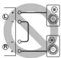
Pnc.1
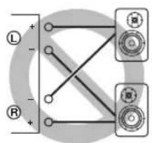
Pnc.2
He noKIOuayTe aKTHBbI ca6Byeep K TepMHaIaM SPEAKERS L/R CH. IooKIOUHTe ca6Byeep K rHe3dAm PRE OUT Ha annapate.
Поклоченье колонok
McnoJb3ObaHne Ka6eJeN KOJHOK
1 ydaIte npn6n3ntbHo 10 MM n3OJauNHO CIOa Ha KOHcX KaKdOro Ka6eJa KOnOHKn I NLOTHo CKpyTHe OTKpbITbIe npoBoda Ka6eJa IJI npedOTbpaueHn KOpOTKO 3aMbikHn.
2 Otkpytnte roIOBky kaxdoro TepMNHaJa KOLOHKn, a 3aTeM BCTaBbTe OOrJeHHbI npOBd B 60KOBoe OTBepCTne Ha TepMNHaJe.
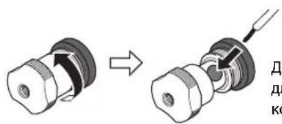
Bce noKluoyehna DOnJXhbl 6bIb npabInhblIMn: L (neBbl) K L, R (npabbl) K R, "+" K " " " " " " .HfOpmauio o npoueype noKnluoyehn CM. BpykoOaCTBe nolb3oBaTeTn KOHOHK.
IcnoB3OBAHne Ka6eNe c 6aHaHOBbIM uTekepom
(MoJIeJIH IIJI CIIIA, KaHaIbI, ABCTpaiHH, KITraN TaIbAH)
Chaana 3akpyTnte roNoBky Ha TepMNHaNe SPEAKERS n 3aTeM BCTaBBte 6aHaHOBBI uTeKepe H hakoHeuHK roNoBKn.
IcnoIb3OBAHne Ka6eJe c BnIKoo6pa3HbIM HaKOHeuHNKOM
10TKpyTNTe rOIOBky n 3aTeM BCTaBbTe BnIKOO6pa3HbI HaKOHeuHk MeKdy KOJIbueBOJ YacTbIO N OCHOBaHmE TepMNHaJa.
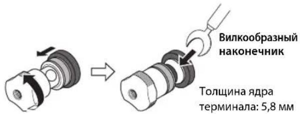
23akpytute roNoBky.
YeTbIpexnpoBODhoe NOdkJIOUcHne
YcTbipexIPOBOHOIOEIOIKIOOHIEIO3BOJIaETOTIDJITB HIN3KHe YAcTOTbIOTINHAna3OHa cpeIHnX N BbICOKHX YacTOT.KoIOHNK, KOTOpBIE IOIDePJKHbAOT YcTbipexIPOBOHOIOEIOIKIOOHcHc, HMeOT DBe IapbI TepMHNAIOB (BCero YoCTbipe TepMHNAJa).OTN DBe IapbI TepMHNAIOB IO3BOJIaOT pa3DEJHTB KOIOHK Ha DBe He3aBNCMbIte IpyII.ДЯ TaKOrTO TIIIA IOIKIOHcHn HEO6XoIMMO IIpHCOeIHINTb IIpHBOblcpeIHnx H BbICOKHX YAcTOT K OIOH Iape TepMHNAIOB,a IIpHBOblI HIN3KHX YAcTOT KpyToI Nape TepMHNAIOB.
1ydaJIte 3aMbIkaUoUne nepeMbIcKu nn MOCTIKN Ha KOJOhKaX.
2NoKIOUHTe annapaT K KOLOHkAm, KaK noka3aHO ha pucyHke HIXKe.
Ppimep nooknueHnaeBoro KaHana
3aHnaHn b annapata KonoHa
3yctaHOBnte ceneKTop SPEAKERS Ha nepeDnei naneB noLoXeHne A+B BI-WIRING.
Покlioqueeя
CmmMeTpnuHoe coeHHHeHne
MoKHOIOIKIOHTb CCTCBOH HIN CD-HPONHPBbATEIb, KOtOpHmEe CHMMETPHHbIE BIXOHNbIE THe3Ja THIIa XLR, K BXoNtbe THe3Ja BAL Ha annapate, JnlaHnro coeHHHeHHn HCIOJIb3yITc CHMMETPHHbIC Ka6CJIN THIIa XLR.
CeJekrop ATTENUATOR: IO3BOJIaCT yCTaHaBJIHBaTb DOIyCTHMbI yPOBeH bXoIHHO rHrHaJa IIN CHMMCTPNHbIX BXoIHbIX rHc3d. Bb6epntc 3HaueChnC ATT. (-6 b) ecJIn ayDIOCHrHaJI, BBIOHMbI n3 IIOKJIHOHHOrO KOMIOHeHTa, 3ByHT NCKaKeHHO.
CeJekTop PHASE: IIO3BOJnAET yCTaHaBJIHBaTb IIOJOKcHHe (IOJIApHOCTb) KOHTaKTa HOT (KOHTaKTa #2: HOT HIN KOHTaTa #3: HOT) Ha cHMMeTpHuHbIX BXOHNbIX rHe3dax.
NORMAL
(KoHTaKT #2: HOT)

INV.
(KoHTaKT #3: HOT)

O6paTHTecb K pyKOBOIDCTBY IIO IIOKJIIOHCHHOMY KOMIIHOHeHTy, YTO6bl y3HaTB IIOJOKeHne KOHTaKTA HOT B CHMMETPNHbIX BbIXOINbIX THe3JAX KOMIIHOHeHTa.
PpimeyaHne
- Bb6epnte 3haueHne NORMAL (KoHTaKT #2 ABnEerTc KOHTaKTOM HOT) nI npOnrpbBaTeNa YamaHa.
He nCnoB3yIte CmmMeTpnuHbIe HecmMmTpnuHbIe COeINHeHnI DnOdHO KOMNoHEHa ODHOBpeMeHHo.3To MoKeT cOpMnpoBaT KoHTyp 3a3EmHeH, KOtOpbIc CO3daeCTaTnueCKne NOMExu Wym.
-Пи NOДКЛЮЧЕНИ Kа6Я OБЯ3ATENBHO COBMECTNTE KOHTaKbI pa3bema COTBepCTNMA rHe3da, a 3aTeM BCTaBBTe WTeKePbI pa3bem XLR B rHe3do Do uenka. YTo6bl OTCoEINHnTb Ka6eNb, HaxMITE n ydepxuBaIte pbyaXOK Ha BXOHNIE rHe3De BAL n BbTaUNTe WTeKePbI pa3bem XLR n3 rHe3Da.
-ДясnmmetpnuHOro coeHHeHnBbIepnte BAL B KaueCTBe NCTOuHnKa BXODHOro CnHana.
Tprrrephoe coeHenne
MoKIO IOIJKIOHOHTb AV-pcCHBepYamaHa HIN IpyrO KOMIOHcHIT, KOtOpBIOIOIDcPKHBacT TpHITcPHyIO YHKUHO. MoKIO yIpaBIAITb DaHHbIM aIInapaTOM CHNxPOHNO CIOIKJIOUeHHbIM KOMIOHEHTOM.
3aHnaHnB annapata
AV-pecuBep Yamaha unn pyroon KOMNOHENT, KOtOpbI uMeet rHe3da TRIGGER OUT n rHe3da PRE OUT
IIPNB KJIIOHHeHHIITaHHIIOKJIIOUeHHORO KOMIOHOHTA IIITAHHe aIHApATA TaKKe BKIOHOAcTc. OIOHOpeMeHHO c ETHM B KaueCTBe HCTOHHKa BXOIOHO CnHaJa Ha aIHapat yCTaHaBJIHBaetc3HaueHHe MAIN DIRECT. EcIN 3HaueHHe MAIN DIRECT BbI6paHO B KaueCTbe HCTOHHKa BXOIOHO CNTHaJa IJIA DaHHOro aIHApata Ha MOMeHT, KOJa BbIKIOHaeTc IITaHHe IOIKIOHOeHHORO KOMIOHOHTa, daHHbI aIHApAT IepeNCT B pCKHM OKNDAHII.
PpMeyaHne
Korda nepekliouateIb nItaHnHa annapaTe yctaHOBHeN B noLoXeHne OFF, nItaHne annapaTa He 6ydt BKlOuaTbcra.
Дистанционhoe coeHHeHne
Unpablenhe annapaTom n3 pyroKOMHaTbl
IpiHIOIKJIOeHHN HMeOIIIErOcB IIpoJaKe HnΦpaKpachoro IprHemHKa H IpePaTtHKa K THe3dAm REMOTE IN/OUT Ha annapate MoKHO yIpaBJIaTB aIcapaTOM H/HIN BHEIHINM KOMIOHcHTOM H3 dpyroH KOMHaTbC IIMOIIbIoo IIpHlaeraMOro IIyIbTa IV.
ДиctaHcHIOHHOe coeHHeHMe MeKdY KOMnoHEHTamYama
Ipn HauHnHpyTOro KOMIOHeHTaYamaH, KOtOpbI IIOJIepKHBactyHKINHOINCTAHINOHHO CoeINHEHHA, HET HeO6XODIMOCTHB INHΦpaKpachOM IpePaTHKE. IIOJIOHOHTe HHΦpaKpaChbI IIpHcMHNK K THe3dAM REMOTE IN/OUT Ha aIIapare, KaK IOKa3aHO HnKe. MoKHO HAcTPOINTb IO Tpex KOMIOHeHTOB YamaHa (BkIOUHaa DaHHbI aIIIapat) Ha INCTaHIIOHHOe coeINHEHne.
Подклоченя
BxOHaHyBCTBnTeNbHOCTb/BxOHaHoe
conpoTnBJIeHne(1KΓU,100BT/8OM)
PHONO (MC)
150MKB, cpeINHeKBaIpaTHHoe 3HaueHHe/50 OM
PHONO (MM)
3,5MBcpeINHeKBAipaTHHoe3HaueHHe/47KOM
CD (HJIn aHaJIIOIHTHHbI)
200 MB, cpeIHeKBAipaTHHoe 3HaueHHe/47 KOM
MAIN IN
1B, cpeIHeKBA,IpaTHuHoe 3HaueHHe/47 KOM
BAL
200 mB, cpeHneKBaIpaTHHoe 3NaueHHe/100 KOM
MaKcMaJIbHoe HanpJxKeHne BXoDHOro CnHaHa
(1 KΓι, 0,5% KΗΝ)
PHONO (MC)
2,0MB,cpedekbaipatHoe3aueHne
PHONO (MM)
50MB,cpeHnEKBaIpaTHHoe3haueHHe
CD (HJn aHaJIOTNHTbI)
2,80B,cpEHeKBaIpaTHHoe3HaueHHe
BAL
BYPASS.....2,80 B, cpeIHeKBAIpaTHHoe 3NaueHne
ATT. (-6日 .5,60B,cpeINHeKBAIpaTHHoe3HaueHne
HomHaJIbHoe BbIXOdHoe HApJxKeHne/BbIXoDHe
COnpoTnBnEHN
LINE 2 OUT
200 MB, cpeHHeKBaIpaTHNHOe 3NaueHHe / 1,5 KOM
PRE OUT
1B,cpedekBaipnHoe3naeHne/1,5KOM
HomHaJIbHaB bIXOJHa MOnHocTb pa3beMa IJIa
HayshnkoB (1 kT4, 32 OM, 0,2% KHN)
50MBT+50MBT
YacToTHaXapaKTePncTnKa
or 5 do 100 . +0 / - 3d
or 20 Fn do 20 Kf.. +0 / - 0,3 nB
OTKNOHeHnO T KBaJau3epa RIAA
PHONO (MM/MC) ±0,5 ΩB
Ko3ΦnueHHeHHeHbIX NCKaKeHm C yyeTOM Wyma (JEITA, BxoD 0,5 B, oT 20 T do 20 Kf)
2-KaHaJIbHbI
PHONO (MC) LINE 2 OUT,
1,2B,cpEINHeKBaIpaTnHoe3HaueHHe.0.02%
PHONO (MM) LINE 2 OUT,
1,2B,cpEINHeKBaipnHHe3HaueHHe.0,005%
CD (HJIN aHaJIIOrHnHbI) / BAL
SPEAKERS OUT, 50Bt / 8OM . 0.035%
[MoJIeJIH IJIa CIIIA n KaIaIbI]
120B IepemHoro ToKa,60
[ModJIbIJIaKHTa] 220B IepeMeHHOro ToKa,50 T
[MoJIbIaKOpEn]
220B IIepemEHHO ToKa,60I
[MoIeJIbIIIAABCTpaJIHH] 240B IIepemeHHoro Toka,50T
[MoJIeJIH JIIJ CoEINHeHHOrO KopoJIeBcTBA H cTpAH EbpoiIbI] 230 B IIepemEHHO ToKa, 50 T
[MoJIbIaA3HH] 220-240BIIepeMeHHoTOka,50T/60T
[MoIeJIbIIHa TaIbAIIb] 110B IepemEnHOrTo ToKa,60T
3hepronotpe6neHne
[ModJIbIaIaA3HH] 250BT
[Дугнec moideи] 350 Br
3Hepronotpe6nneBpeKImeOxuHaHna
BbIKIOeHHoe coCToHHe 0,1 Bt
PexHM OxuaHn. 0,2BT
MaKcMaJbHoe 3HepronoTpe6neHne
(1KΓ4OM 10% KHN) [MoeJIbIaTaaBaHa] .700BT
Pazmepbl (UxBxI) 435×157×463MM
Bec
22,7K
*BcoepkaHHHaHHORo pyKOBOCTBa IIpHBeIeHbI IocJIeHNHe Ha MOMeHT IIy6JIHKaIIIN TexHueckHe xapaKTePncTKn. JnI IOJyueHnI NocJIeIHeBepCnI pyKOBOCTBa Iocetntc B6-cain KOpHopaIIYamaHa 3aRpy3HTc paJIc pyKOBOCTBOM.
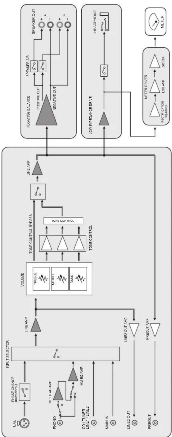
Блok-cхema
Akyctnueckne xapaKTepeNtIKN
XapaKTePncTnK nperynnpOBKn Tem6pa
Ko3ΦHnueHT HeJIHHeiHbIX mCKaXeHHI
Ko3ΦmUeHT HeJIHHeIhBIX mCKaXeHn (PHONO)
Bo3MOxHbIe HencnpaBHOCTn n cnoCo6bl nx yCTpaHeHna
EcJIN daHHbI aIIHapar pa6oTAc HnPaBnIbHO, cm. Ta6JIuY HnKc. EcJIN HeHCnPaBIOCTb He yKa3aHa B Ta6JIuC He HIn Bbl Ic CMOrJIH ycTaPiHTbc ce, cIEyra HnCTpyKuHm Ta6JIuCb, OTKIOHTe aIIHApat, OTCOeIHHTe BnIKy ChIOBOrO Ka6JIa H 6paHTtccb K 6JIHKaIIChMу ABTOpH3OBaHIOMy dJIepy HIn B ccpBnCHbI UcHtp YamaHa.
| Héncπrabnóctb Pmá | Mùna Cnoco6 yctpanenhy | Cm. ctr. | |
| Питанные не вкlioуаетс. | Слобов Кабел He полюочen K разьему AC IN на занд� панени ялnotи не вкlioуен b pozeтуп лесенhoe.TOKa. | Плкюочite слобов Кабел cootbetCTbyuizimMb obpaazom. | 218 |
| Данный поларat полberрся сильному лесгричесму наразожени OT bveшних Incotychikob (надимер, молпя ялп сильhoeстуескoe лесгричесТВ). | Быкюочite поларat, отоедине вилky силього Кабел OT pozetknп лесенhoe.TOKa, поождote okono 30 sekунд, a 3aTe m Choba Плкюочite поларat. | - | |
| Miraertиндаитор (питанные) на зандане панени. | Быla aktnibroвога схема зашитны ИЗ-з-a корOTКОТ замыkaлии I.T.D. | Убадиесь, чTO повoda колонok He сорпискаотся дугс Другом ялnotи He замкинчы КорOTК O с занд� панени данного anppapata, И 3aTe m ChOBа Вкlioочite пitaанe apnapata. | 214 |
| ИмeeТя пооблесma с bHytrpenHIMMсхемам duahHOro annpapata. | Отоединite вилky силього Кабел OT pozetknп лесенhoe.TOKa и образпесь к билжайшему abtoprosobanHomу duinepy ялnotь CBepinchbyцу Yamaha. | - | |
| Кordа поларat вкlioуен, мiraertиндаитор INPUT и уrobenvь громкову сніжачетс. | Быla aktnibroвога схема зашитны ИЗ-з-a корOTKОТ замыkaлии I.T.D. | Убадиесь, чTO повoda колонok He сорпискаотся дугс Другом ялnotи He замкинчы КорOTК O с занд� панени данного anppapata, И 3aTe m ChOBа Вкlioочite пitaанe apnappata. | 214 |
| 3Byk He cIbIshen. | Кабел bIXODA/bixOda Былп полJOUeHbHe He nprapabInlbNo. | Правиьно Плкюочite кабел.Есян сицралость coхраяETcR, kabeni mony T blyde defeKTbIMi. | 212 |
| He blyb bixbpaH cootBETCTBYUOIIu nICTOChNK. | С пошью сileketoppa INPUT Na peredneй панени (илnotи on3 celektorkhix khotok nctouchnika bXodHORO cngHala ha nyltte Dv) b6pepitce COOTBETCTBYUO nCTOCHNK BxodHORO cngHala. | 204, 208 | |
| Сelктор SPEAKERS ystahovlen b noLOJeHne OFF. | Yctahobitce cileketop SPEAKERS B COOTBETCTBYUOUIEE noLOJeHne. | 203 | |
| Кабел кOLOHOK noDklOUeHbH He nprapabInlbNo. | Убадиесь b TOM, чTO kabeni кOLOHOK noDklOUeHbHпrelnyпrel. | 214 | |
| 3Byk HeoxNiDaHNO otKlIOUaETcR. | Быla aktnibroвога схема зашитны ИЗ-з-a корOTKОТ замыkaлии I.T.D. | Убадиесь, чTO повoda колонok He сорпискаотся дугс Другом ялnotи He zamkhytBu koperTOK O caiiHne панени duanHORO anppapata, И 3aTe m ChOBa Bklioочite пitaанe apnapata. | 214 |
| Невозможно отreynlpoBaTb уrobenvь громкову. | Вагиант MAIN DIRECT bixbpaH b KaueCTBE nCTOCHNKA BXODHORO CngHala. | ОтreynlpoуITE grpOMKOCTb Ha NOKLIOUeHOM komOneHTe.Лбio noDklIOUeT BVEHNIH KMOnOHENT K nape bXodHbIX TNe3d, OTlinhbx OT TNe3d MAIN IN, a 3aTe m Bixbepitce COOTBETCTBYUOUIIN nCTOCHNK BXODHORO CngHala. | 204 |
| 3Byk cIbIshen n3 колонку Только odhoro kaHana. | Восprion3BVDaIaI KOMIOHENT IITI KOLIOHKN IocklIOUeHbH He nprapabInlbNo. | Убадиесь b TOM, чTO onH N noDklIOUeHbI nprapabInlbNo.Есян сицралostь coхраяETcR, kabeni mony T blyde defeKTbIMi. | 212 |
| Баланс уrobNV rplomKOSTm Mejdу правои и levoь кOLOHKO NaCTPOeH He nprapabInlbNo. | Насточite balaNC uroBWA grpOMKOSTm Mejdу правои и levoь кOLOHKO C noLOUbIOperugTApora BALANCE. | 204 | |
| Hemcpabnoctb Пии | ИннСоб устра themselves | См.ст. | |
| Hedocstakok Hn3kxчачот otii OTCYCTBne npoctpaHCTBeHHoro obbema 3Byka. | Провoda + и - на усilnteile яйno колонкх полочец b с Нерравильно полочью. | Порклочite п探测oda koLOHOK c npabinbnoi полочью + и -. | 214 |
| Cblshen rhyaichi 3Byk. | Кабел Bxoda/bxoda 6blni рдклочьи He nprabavilho. | Правиьно роглочite kaobel.Если Исирваэгость coхразяется, kabelen могут 6bltdeфektbIMM. | 212 |
| Прогрьател Ne 3azemlen chepe3 terminaJI GND. | Порклочite п探测ьател K tepminaIaity GND daHHoro annapata. | 212 | |
| Восpron3beDeHne aynocnHala c komnoenta,poKlquChHoro K bXoHbIe rHeZda BAL,3ByuHT nCKaJehNo. | Уровьс Сигнада в Симmetричны BXODhix rHe3dax npebbyshaet Дупystimь BXODнoi уровь. | Есни уровьс сигнада в симmetriчны BXODны rHe3dax TINA XLR na PodknloeuHOM BOCPON3BOJaIeM KOMIOHENTe BДBA pa3a 6oblle neо copaHEHIO C HeCIMMeTPrUHbIMn rHe3dAmR RCA,yctaHOBITE celenkToPT ATTENUATOR, paoNoloxeHbIy noD BVODHbIMn rHe3dAmR, B noLOXeHIne ATT.(-6 nb). | 216 |
| В полсх чаotax oTeUTcBvET rIy6Hna, korga blybpaHO 3NauchHeme BAL. | Неверhoe зачение поларноctи. | Быберite п探测ьну loЯрноctь сnomoцьо celenkTopta PHASE. | 216 |
| Восpron3beHne aynocnHala nckaKeHo pri npoclyushaHin noKlquChHoro CD- npOrrpmbatela nII mArgHtIofoHa chepe3 hayuHnki (poKlquChHoro K CD- npOrrpmbatela nII mArgHtIofoHa). | Питане annapata BykIoucheNo. BkIoucheNe.Te nitaHne annapata.202 | ||
| UroBENr rgomKoSTn BnHnIOBoi PlaactINHKn CnIshKom Hn3Kni. | ПereKlquAtel PHONO Na peednei panel YuSTaHOBe n B He nprabavilbHoe noLoJoxeHne. | ПereVeDite nepeKlquAtel PHONO B noLoJoxeHne MM niu MC B COOTBETCTBNI C TINOM MaHHTHOn IToLOBKN 3BykoCHImaTeI npOriPrbVbATEn. | 205 |
| PnybT Dny pa6oTaet nAldexaamn 6bpa3om. | ПульТ ДУ Incponbayetca 3a peedanmi pa6oJero dinana3OHa. | ПульТ ДУ doJolgenicnoBzOATcBcR a peedenax MAKCIMaMbHOrO paCCTOraHnB 6Mi noD yIgmoHne 6Boee 30 rpaIycov BheOceBOrO OTKIOHeHnO tCeHcopa Dny ha peednei paneHn. | 210 |
| Празмoe noPadaHne coNHeHbIX nueyei nii ocBeSeHnna (OT InHBeptHnO fHyopeceHTHO nIamMb, CTpo6ckOHa n T.D.) Ha ceHcop Dny ha peednei paneHn. | Изmedite opineHaio zuIcTOchNka CBeta nII npOLOXeHne annapata. | - | |
| Раразженьble 6bataeKn. Поменайte Ece 6bateKn.210 |
TexHnueckoe 6cnyxmbaHne
Бokobbie naHei n 3epKaIbHbIM NOKpbITnEM
PekomeHdyetc HIOJB3OBaTb YNCTBHyIO caJIqTeKy, aHaJOIRHyIO caJIqTeKam IJIΦopTreHaHO.
Дргпе NOBepxHoctn
He HcIOJIb3yIte IJr YHCTKIN XHMHueckne BeIEeCTBa, TaKHe KaK 6eH3HH HIN pa36aBHTeJI. B IpOTHBOM cIiyae 3TO MOKeT IOBpeIHITb IOBepxHOCTH. IIpoTHpaTe IOBepxHOCTM rIKoN cyXOH TKAHIO.


- Features
- Things to know before using this product
- About this manual
- Supplied accessories
- Table of Contents
- Part Names and Functions
- Front panel
- (Power) switch/indicator
- NOTICE
- Note
- ② Remote control sensor
- ③PHONES jack
- ④TRIM selector
- Available gain:
- ⑤SPEAKERS selector
- ⑥METER selector
- ⑦Meter (LEFT/RIGHT)
- BASS control
- ⑨TREBLE control
- 10BALANCE control
- ⑪INPUT selector/indicator
- ⑫PHONO switch
- 13Feet
- AUDIO MUTE switch/indicator
- 15VOLUME knob
- Rear panel
- ① BAL (balanced) input jacks
- PRE OUT jacks
- ③ AUTO POWER STANDBY switch
- ④TRIGGER IN jack
- ⑤REMOTE IN/OUT jacks
- ⑥ SERVICE jack
- ⑦SPEAKERS L/R CH terminals
- 8TUNER input jacks
- ⑨PHONO input jacks
- CD input jacks
- ① GND (Ground) terminal
- CAUTION
- LINE 1 input jacks
- LINE 2 jacks
- 14MAIN IN jacks
- 15AC IN jack
- Remote control
- ① Infrared signal transmitter
- ② AMP key
- ③Input select keys
- ④VOLUME+/-keys
- ⑤MUTEkey
- ⑥ Tuner control keys
- CD player control keys
- ■Installing batteries in the remote control
- Operating the remote control
- Connections
- Connection diagram
- Connecting speakers
- Using speaker cables
- Using banana plug cables
- First tighten the knob on the SPEAKERS terminal, and then insert the banana plug into the head of the knob.
- Using Y-shaped lug cables
- 1Unscrew the knob, and then sandwich the Y-shaped lug between the ring part and base of the terminal.
- 2Tighten the knob.
- Bi-wired connection
- Remove the shorting bars or bridges on the speakers.
- 2Connect this unit to the speakers as shown in the figure below.
- 3Set the SPEAKERS selector on the front panel to A+B BI-WIRING.
- Balanced connection
- Trigger connection
- Remote connection
- ■Operating the unit from another room
- Remote connection between Yamaha components
- Connecting the power cable
- Appendix
- Channel separation (JEITA, 1 kHz/10 kHz)
- Tone control characteristics
- Power supply
- Power consumption
- Standby power consumption
- Maximum power consumption (1 kHz, 4Ω 10% THD)
- Dimensions (W× H× D)
- Weight
- Acoustic characteristics
- Troubleshooting
- Maintenance
- Mirror-finish side panels
- Other surfaces
- ⑤Prises REMOTE IN/OUT
- Consummation maximum (1 kHz, 4Ω, DHT 10%)
- ⑤REMOTE IN/OUT-uttag
- ⑥SERVICE-uttag
- Effektbandbredd (0,1% THD, 45 W)
- Dämpningsfaktor (1 kHz)
- Maximal signalspanning vid ingang (1 kHz, 0,5% THD)
- Matten (B× H× D)
- Vikt
- ⑤Prese REMOTE IN/OUT
- Collegamento bi-wire
- Rumore residuo (rete IHF-A)
- Consumo energetico in standby
- ⑤Tomas REMOTE IN/OUT
- Vermogensbandbreedte (0,1\%) THD, 45 W
- PoctabIyemblie akceccyapbl
- Copepknne
- Ha3BaHnY KOMNoHErTOB IN IX ΦyHKuIN
- Ha3BaHЯ KOMnoHeTOb Inx ΦyHKcIa
- PepednnaHeIb
- YAMAHA
- NepeKIOUaTeNb/MHdNKaTOp (NTaHne)
- YBEOMJIEHNE
- Ha3BaHЯ KOMnoHeTObи nx φyHKcIn
- Передна панелb
- ⑧PerylaTop BASS
- ⑨PerynTop TREBLE
- ⑥ PeryIaTOp BALANCE
- PpMueHne
- ⑪CenekTop/нднkaTOp INPUT
- PpimueaHne
- ⑫ NepeKIOuOaTeIb PHONO
- PpumeyaHne
- YBEOMJIENHE
- Ha3BaHЯ KOMnoHETOBи nx φункциn
- 3aHЯ paHeIb
- ① BxoDhbIe rHe3da BAL (cMMMeTpUHbIe)
- PpmeaHne
- ② THe3a PRE OUT
- PpMueaHne
- ③ NpeeklouaTeIb AUTO POWER STANDBY
- ④THe3doTRIGGERIN
- ⑤Гнэзда REMOTE IN/OUT
- ⑥Γhe3do SERVICE
- ⑦TepMNHaJIbI SPEAKERS L/R CH
- BxOaHbIe rHe3da TUNER
- BxOДьгнEЗДa PHONO
- 10BxOxDhIe rHe3da CD
- ⑪TepmHaI GND (3a3eMneHne)
- BHIMMAHNE
- ②BxoOpHbIe rHe3da LINE 1
- 13He3da LINE 2
- 14THe3da MAIN IN
- YBEDOMJEHNE
- 15THe3do AC IN
- NynbT dy
- YBEDOMJIENHE
- ⑤KhoNka MUTE
- ⑥ Khonkn ynpaBneHn TIOhePOM
- ⑦ KhonknynpaBneHna CD-npounrpbIbaTeTneM
- Прмочинe
- Ha3BaHЯ KOMnoHeTOb Inx φyHKcIe
- YcTaHOBka 6aTapeek B nynbT dY
- Unpablenne c nomoubIO npbTa dy
- Подключения
- Cxema nodkloueHna
- BHIMAHVE
- Поклоченье колонok
- McnoJb3ObaHne Ka6eJeN KOJHOK
- IcnoB3OBAHne Ka6eNe c 6aHaHOBbIM uTekepom
- Chaana 3akpyTnte roNoBky Ha TepMNHaNe SPEAKERS n 3aTeM BCTaBBte 6aHaHOBBI uTeKepe H hakoHeuHK roNoBKn.
- IcnoIb3OBAHne Ka6eJe c BnIKoo6pa3HbIM HaKOHeuHNKOM
- YeTbIpexnpoBODhoe NOdkJIOUcHne
- Покlioqueeя
- CmmMeTpnuHoe coeHHHeHne
- NORMAL
- INV.
- PpimeyaHne
- Tprrrephoe coeHenne
- PpMeyaHne
- Дистанционhoe coeHHeHne
- Unpablenhe annapaTom n3 pyroKOMHaTbl
- ДиctaHcHIOHHOe coeHHeHMe MeKdY KOMnoHEHTamYama
- Подклоченя
- BxOHaHyBCTBnTeNbHOCTb/BxOHaHoe
- MaKcMaJIbHoe HanpJxKeHne BXoDHOro CnHaHa
- HomHaJIbHoe BbIXOdHoe HApJxKeHne/BbIXoDHe
- COnpoTnBnEHN
- HomHaJIbHaB bIXOJHa MOnHocTb pa3beMa IJIa
- YacToTHaXapaKTePncTnKa
- OTKNOHeHnO T KBaJau3epa RIAA
- Ko3ΦnueHHeHHeHbIX NCKaKeHm C yyeTOM Wyma (JEITA, BxoD 0,5 B, oT 20 T do 20 Kf)
- 2-KaHaJIbHbI
- 3hepronotpe6neHne
- 3Hepronotpe6nneBpeKImeOxuHaHna
- MaKcMaJbHoe 3HepronoTpe6neHne
- Bec
- Akyctnueckne xapaKTepeNtIKN
- Bo3MOxHbIe HencnpaBHOCTn n cnoCo6bl nx yCTpaHeHna
- TexHnueckoe 6cnyxmbaHne
- Дргпе NOBepxHoctn
Brand : YAMAHA
Model : AS2200
Category : Home cinema amp