
Sega EY3544 - Cordless electric saw PANASONIC - Free user manual and instructions
Find the device manual for free Sega EY3544 PANASONIC in PDF.
| Product type | Cordless reciprocating saw |
| Brand | Panasonic |
| Model | EY3544 |
| Rated voltage | 18 V DC |
| Battery type | Ni-MH (model EY9251) |
| Battery capacity | 3.5 Ah |
| Stroke length | 23 mm (7/8 in) |
| Cutting speed (no load) | 0 - 2,700 cpm |
| Blade shank type | 13 mm (1/2 in) universal |
| Overall length | 491 mm (19-5/16 in) |
| Weight (with battery) | 3.9 kg (8.7 lb) |
| Included charger | Model EY0110, line voltage varies by country |
| Charging time (3.5 Ah battery) | Approximately 65 minutes |
| Adjustable shoe | Yes, tool-free adjustable |
| Variable speed trigger | Yes, progressive trigger |
| Safety lock | Switch lock lever |
| Cuttable materials | Wood, metal, plastic |
| Recommended cutting fluid | Cutting oil for metal |
| Operating temperature | 0 °C to 40 °C |
| Blade clamp maintenance | Clean and lubricate with dry lubricant |
| Warranty | Consult your dealer (not specified in manual) |
Frequently Asked Questions - Sega EY3544 PANASONIC
User questions about Sega EY3544 PANASONIC
0 question about this device. Answer the ones you know or ask your own.
Ask a new question about this device
Download the instructions for your Cordless electric saw in PDF format for free! Find your manual Sega EY3544 - PANASONIC and take your electronic device back in hand. On this page are published all the documents necessary for the use of your device. Sega EY3544 by PANASONIC.
USER MANUAL Sega EY3544 PANASONIC
Cordless Reciprocating Saw
Akku-Reciprosäge
natural_image
Technical line drawing of a handheld power tool with handle and internal components (no text or symbols)Before operating this unit, please read these instructions completely and save this manual for future use.
| (A) | ShoeFührungsschuhSabotPattinoSchoenZapataSkoSkoSkoKenkäОснованиеОснова | (B) | Blade clampSägeblattklemmeSerre-lameMorsetto della lamaZaagbladklemAbrazadera de cuchillaSavbladsklemmeBladklämmaBladklampTerän kiinnitinФиксатор полотнаФіксатор полотна | (C) | Blade clamp sleeveSägeblatt-KlemmringManchon de serre-lameManicotto del morsetto della lamaZaagbladklemmofManguito de abrazadera de cuchillaSavblad-klemringBladklämmhylsaBladklamphylseTerän kiinnittimen holkkiФиксирующая соединительная муфтаФіксуюча з'єднувальна муфта |
| (D) | SliderSchieberGlissièrePiano inclinatoSchuifstukDeslizadorSkyderLöparetSleidLiu'utinПолзунПовзун | (E) | Switch lock leverEinschaltsperrn marche avantLevier de verrouillage de CommutateurLeva di bloccaggio dell'interruttoreSchakelaarblokkeerhendelPalanca de bloqueo del interruptorOmskifterlåsearmenOmkopplarlåsspakBryterlåsKytkimen lukkovipuРычаг блокировки переключателяВажіль блокування перемикача | (F) | Trigger switchElektronikschalterCommutateur à gâchetteGrilletto interruttoreTrekschakelaarInterruptor de activaciónTrykkerVippströmställareUtløserbryterLaukaisinkytkinПусковой переключательПусковий перемикач |
| (G) | Battery pack (EY9251)Akkupack (EY9251)Batterie (EY9251)Pacco batteria (EY9251)Accu (EY9251)Bloque de pilas (EY9251)Batteri (EY9251)Batteri (EY9251)Batteri-pakke (EY9251)Akku (EY9251)Батарейный блок (EY9251)Батарейний блок (EY9251) | (H) | Insulated rubber bootGummi-IsolierungSoufflet en caoutchouc isoléCappuccio di gomma isolanteGeïsoleerde rubberhoesFunda de caucho aisladaGummi-isoleringIsolerad gummikängaIsolert gummistøvelKumieristeИзолирующий резиновый кожухІзолючий резиновый кожух | (I) | Shoe lock leverFührungsschuh-ArretierhebelLevier de verrouillage de sabotLeva di bloccaggio del pattinoSchoenblokkeerhendelPalanca del seguro de zapataSkolåsearmSkolåsspakSkolåsKengän lukkovipuРычаг блокировки основанияВажіль блокування основи |
| (J) | Saw bladeSägeblattLame de scieLama della segaZaagbladCuchilla de sierraSavbladSågbladSagbladSahanteräПолотно пилыПолотно пили | (K) | Battery charger (EY0110)Ladegerät (EY0110)Chargeur de batterie (EY0110)Carica-batterie (EY0110)Batterijlader (EY0110)Cargador de la bateria (EY0110)Batterioplader (EY0110)Batteriladdare (EY0110)Batterilader (EY0110)Akkulaturi (EY0110)Зарядное устройство (EY0110)Зарядний пристрій (EY0110) | ||
Read "the Safety Instructions" booklet and the following before using.
I. ADDITIONAL SAFETY RULES
1) Keep hands away from cutting area and blade. Keep your insulated gripping surfaces.
If both hands are holding the saw, they cannot be cut by the blade.
2) Never hold piece being cut in your hands or across your leg. It is important to support the work properly to minimize body exposure or loss of control.
3) Hold tool by insulated gripping surfaces when performing an operation where the cutting tool may contact hidden wiring.
Contact with a "live" wire will also make exposed metal parts of the tool "live" and shock the operator.
4) Be aware that this tool is always in an operating condition, since it does not have to be plugged into an electrical outlet.
5) Always use safety goggles or glasses with side shields.
Ordinary eye or sun glasses are NOT safety glasses.
6) When this tool is used for wood-working in confined areas (e.g. indoors), wear dust mask.
7) Avoid cutting nails. Inspect workpiece for any nails and remove them before operation.
8) Do not cut oversized workpiece.
9) Check for the proper clearance beyond the workpiece before cutting so that the blade will not strike the floor, workbench, etc.
10) Hold the tool firmly.
11) Make sure the blade is not contacting the workpiece before the switch is turned on.
12) Keep hands away from moving parts.
13) Do not touch the blade or workpiece immediately after opera-
tion; they may be extremely hot and could burn your skin.
14) Never swing Reciprocating Saw.
15) Do not use blades which are deformed or cracked.
16) Do not use blades which do not comply with the characteristics specified in these instructions.
17) Remove the battery pack from the tool body before replacement of the blade, making adjustments, or other maintenance work.
18) Wear ear protectors when using the tool for extended periods.
II.ASEMBLY
WARNING:
To reduce the risk of injury, always remove battery pack before changing the blade.
Selecting a blade
The blade clamp sleeve can be used with all 1/2" shank universal reciprocating saw blade. When selecting a blade, choose the right type and length.
Choose a length long enough to extend beyond the shoe and your work throughout the stroke. Do not use blades less than 3-9/16" (90 mm) long since they will not extend beyond the shoe throughout the stroke.
Installing or removing the saw blade
CAUTION:
Always clean out all chips or foreign material adhering to the blade, blade clamp and/or slider before use. Failure to do so may cause insufficient tightening of the blade, resulting in a serious injury.
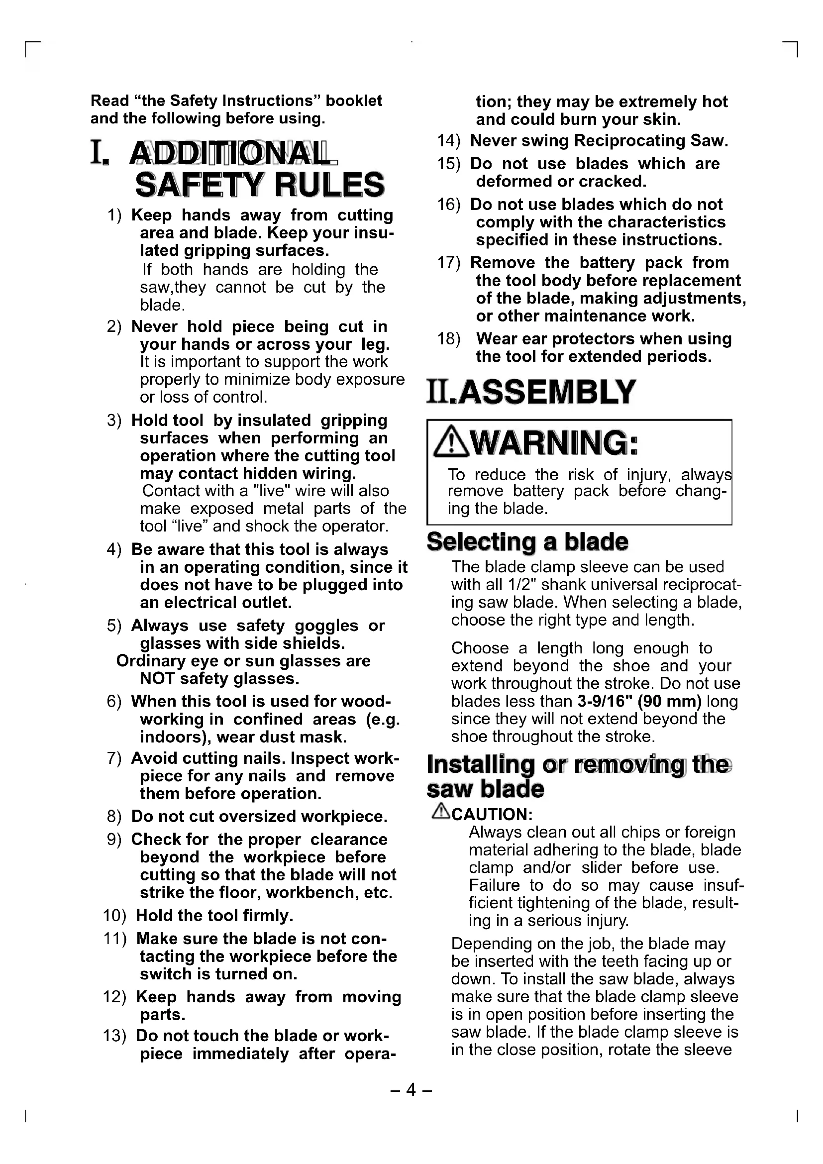
Depending on the job, the blade may be inserted with the teeth facing up or down. To install the saw blade, always make sure that the blade clamp sleeve is in open position before inserting the saw blade. If the blade clamp sleeve is in the close position, rotate the sleeve
to the open position until it clicks.
Blade clamp sleeve
natural_image
Diagram of two identical mechanical components with internal gear-like structures, no text or symbols presentOpen position Close position
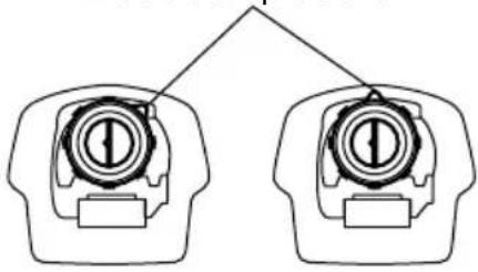
Insert the saw blade into the blade clamp until the saw blade snaps in place and clamp sleeve rotates. When the blade clamp sleeve rotates, the saw blade is fixed. Make sure that the saw blade is firmly fixed and locked. If the blade clamp does not lock properly, have the tool serviced by a qualified repair personnel.
Blade
natural_image
Mechanical diagram showing a tool interacting with a mechanical component (no text or symbols visible)WARNING:
If you do not insert the saw blade deep enough, the saw blade may be ejected unexpectedly during operation. This can be extremely dangerous.
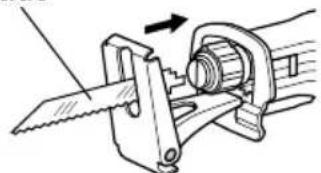
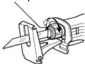
To remove the saw blade, rotate the blade clamp sleeve in the direction of the arrow (clockwise from the front view) fully. The saw blade is removed and the blade clamp sleeve is fixed at the open position. Be careful when handling hot blades after use.
Blade clamp sleeve
natural_image
Technical line drawing of a mechanical clamp or bracket assembly (no text or symbols)NOTE:
If you remove the saw blade without rotating the blade clamp sleeve fully, the sleeve may not be fixed. In this case, rotate the blade clamp sleeve fully, then make the sleeve fixed at the open position.
Blade Clamp Maintenance
Always keep blade clamp sleeve clean and dry after use.
Periodically lubricate blade clamp sleeve with a dry lubricant. Using wet lubricant may keep the dust and debris, and causes malfunction of the blade clamp.
III. OPERATION
Hold tool by the insulated gripping surfaces when performing an operation where the cutting tool may contact hidden wiring.
Always wear safety goggles or glasses with side shields.
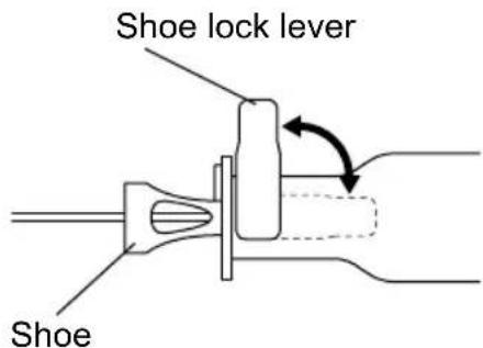
Adjusting shoe
When the blade loses its cutting efficiency in one place along its cutting edge, reposition the shoe to utilize a sharp, unused portion of its cutting edge. This will help to lengthen the life of the blade. To reposition the shoe, loosen the shoe lock lever counter-clockwise and slide the shoe forward or back to the desired position. Then tighten the lever clockwise to firmly secure the shoe.
Switch action
CAUTION:
Before inserting the battery pack into the tool, always check to see that the trigger switch actuates properly and returns to the "OFF" position when released.
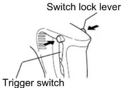
To prevent the trigger switch from being accidentally pulled, a lock-off button switch lock lever is provided. Always make sure the switch is locked when carrying or storing the tool to eliminate unintentional starting. To start the motor, press the switch lock lever, then squeeze the trigger switch.

WARNING:
To reduce the risk of injury, keep hands away from the blade and other moving parts.
Starting and Stopping
To start the tool, grasp the handle firmly. Press the switch lock lever, which can be pressed in from either left or right side of the tool. Then pull the trigger switch.
To stop the tool, release the trigger. Allow the tool to come to a complete stop before removing the blade from a partial cut or before laying the tool down.
Controlling speed by Trigger Switch
The reciprocating saw is equipped with a trigger speed control switch. It may be operated at any speed from zero stroke per minute to full speed. Always start tool before blade contacts the workpiece. To vary the speed, simply increase or decrease the pressure on the trigger. The further the trigger is pulled, the greater the speed.
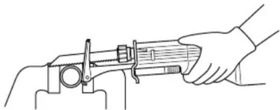
Cutting materials
Before the blade contacts the workpiece, grasp the handle firmly and pull the trigger. Begin cutting at slow speed, gradually increasing speed as you cut. When cutting into materials or hard materials that can not be cut from an edge, drill a starting hole larger than the widest part of the blade.
CAUTION:
• Always press the shoe firmly against the workpiece during operation. If the shoe is held away from the workpiece during operation,
strong vibration and/or twisting will be produced, causing the blade to snap dangerously.
• Always wear gloves to protect your hands from flying hot chips when cutting metal.
• Always use a suitable coolant (cutting oil) when cutting metal. Failure to do so will cause premature blade wear.
- If the tool is operated continuously until the battery pack has discharged, allow the tool to rest for 15 minutes before proceeding with a fresh battery pack.
natural_image
Line drawing of a hand using a caliper to measure a cylindrical object (no text or symbols present)Press the shoe firmly against the workpiece. Do not allow the tool to bounce. Bring the blade into light contact with the workpiece. First, make a pilot groove, using a slower speed. Then use a faster speed to continue cutting.
For Appropriate use of Battery pack
Ni-MH Battery pack (EY9251)
Charge the Ni-MH battery fully be- fore storage in order to ensure a longer service life.
The ambient temperature range is between 0^ C ( 32^ F) and 40^ C ( 104^ F).
If the battery pack is used when the battery temperature is below 0^ C ( 32^ F), the tool may fail to function properly. In that case, charge the battery until charging is completed for appropriate functioning of the battery.
When battery pack is not in use, keep it away from other metal objects like: paper clips, coins, keys, nails, screws, or other small metal objects that can make a connection from one terminal to another.
Shorting the battery terminals together may cause sparks, burns or a fire.
When operating with a Ni-MH battery pack, make sure the place is well-ventilated.
Battery Pack Life
The rechargeable batteries have a limited life. If operation time becomes extremely short after recharging, replace the battery pack with a new one.
NOTE:
Use under extremely hot or cold conditions will reduce operating capacity per charge.
Battery Recycling
ATTENTION:
For environmental protection and recycling of materials, be sure that it is disposed of at an officially assigned location, if there is one in your country.
Charging
NOTE:
When you charge the battery pack for the first time, or after prolonged storage, charge it for about 24 hours to bring the batteries up to full capacity.
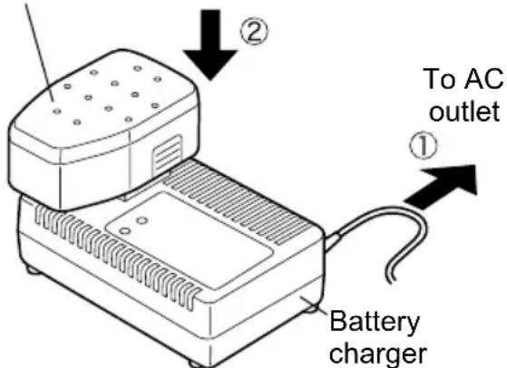
Battery charger (EY0110)
- Plug the charger into the AC outlet.
NOTE:
Sparks may be produced when the plug is inserted into the AC power supply, but this is not a problem in terms of safety.
- Insert the battery pack firmly into the charger.
Battry pack
- During charging, the charging lamp will be lit.
When charging is completed, an
internal electronic switch will automatically be triggered to prevent overcharging.
- Charging will not start if the battery pack is warm (for example, immediately after heavy-duty operation). The orange standby lamp will be lit until the battery cools down. Charging will then begin automatically.
-
When charging is completed, the charging lamp will start flashing quickly in green color.
-
When in any of the conditions that battery pack is too cool, or the battery pack has not been used for a long time, the charging lamp is lit. In this case charging takes longer to fully charge the battery pack, than the standard charging time.
- If a fully charged battery pack is inserted into the charger again, the charging lamp light up. After several minutes, the charging lamp may flash quickly to indicate the charging is completed.
- If the charging lamp does not light immediately after the charger is plugged in, or if after the standard charging time the lamp does not go off, consult an authorized dealer.
NOTE:
- When charging a cool battery pack (below 5^ (41°F)) in a warm place, leave the battery pack at the place and wait for more than one hour to warm up the battery to the level of the ambient temperature. Otherwise battery pack may not be fully charged.
- Cool down the charger when charging more than two battery packs consecutively.
- Do not insert your fingers into contact hole, when holding charger or any other occasions.
CAUTION:
- Do not use power source from an engine generator.
This can damage the charger and present the risk of fire or personal injury.
- Do not cover vent holes on the charger and the battery pack.
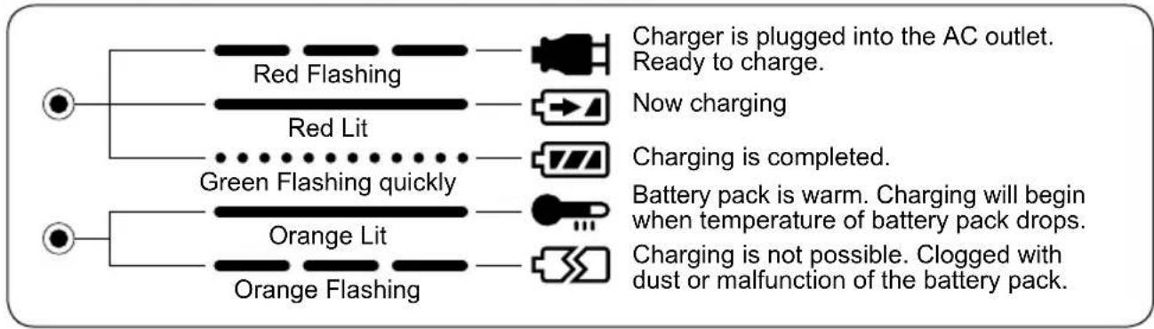
IV. LAMP INDICATIONS
flowchart
graph TD
    A["●"] --> B["Red Flashing"]
    A --> C["Red Lit"]
    A --> D["Green Flashing quickly"]
    A --> E["Orange Lit"]
    A --> F["Orange Flashing"]
    B --> G["Charger is plugged into the AC outlet. Ready to charge."]
    C --> H["Now charging"]
    D --> I["Charging is completed."]
    E --> J["Battery pack is warm. Charging will begin when temperature of battery pack drops."]
    F --> K["Charging is not possible. Clogged with dust or malfunction of the battery pack."]
V. ACCESSORIES
CAUTION:
To prevent the risk of injury, only use accessory or attachment for its stated purpose. If you need any assistance for more details regarding these accessories, ask your local service center.
VI. SPECIFICATIONS
MAIN UNIT
| Model EY3544 | |
| Motor DC Motor 18 V | |
| Length of Strokes 23mm (7/8") | |
| Strokes per Minute 0 ~ 2700 spm | |
| Type of Blade shank 13 mm (1/2") universal reciprocating saw blade | |
| Overall length 491 mm (19 - 5/16") | |
| Weight (with battery pack) 3.9 k | g, (8.7 lbs) |
BATTERY PACK
| Model EY9251 | |
| Storage battery Ni-MH Battery | |
| Battery voltage 18 V DC (1.2 V × 15 cells) | |
BATTERY CHARGER
| Model EY0110 | |||||||
| Electrical rating See the rating plate on the bottom of the charger. | |||||||
| Weight 0.78 k | g, (1.72 lbs.) | ||||||
| Charging time | 7.2V 9.6 | V 12V 15.6V | 18V 24V | ||||
| 1.2Ah | EY9065 | EY9080 | EY9001 | ||||
| EY9066 | EY9086 | EY9006 | |||||
| 20min. | |||||||
| 1.7Ah | EY9180 | EY9101 | |||||
| EY9182 | |||||||
| 25min. | |||||||
| 2.0Ah | EY9168 EY9106 EY9136 EY9117 | ||||||
| 30min. 30min. 60min. | |||||||
| 3.0Ah | EY9200 EY9230 EY9210 | ||||||
| 45min. 90min. | |||||||
| 3.5Ah | EY9201 EY9231 EY9251 | ||||||
| 55min. 65min. | |||||||
NOTE:
This chart may include models that are not available in your area.
Please refer to the catalogue.
ONLY FOR U. K.
VII. ELECTRICAL PLUG INFORMATION
FOR YOUR SAFETY PLEASE READ THE FOLLOWING TEXT CAREFULLY
This appliance is supplied with a moulded three pin mains plug for your safety and convenience.
A 3 amp fuse is fitted in this plug.
Should the fuse need to be replaced please ensure that the replacement fuse has a rating of 3 amp and that it is approved by ASTA or BSI to BS1362.
Check for the ASTA mark or the BSI mark on the body of the fuse.
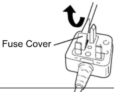
If the plug contains a removable fuse cover you must ensure that it is refitted when the fuse is replaced.
If you lose the fuse cover the plug must not be used until a replacement cover is obtained.
A replacement fuse cover can be purchased from your local Panasonic Dealer.
IF THE FITTED MOULDED PLUG IS UN - SUITABLE FOR THE SOCKET OUTLET IN YOUR HOME THEN THE FUSE SHOULD BE REMOVED AND THE PLUG CUT OFF AND DISPOSED OF SAFELY.
THERE IS A DANGER OF SEVERE ELECTRICAL SHOCK IF THE CUT OFF PLUG IS INSERTED INTO ANY 13 AMP SOCKET.
If a new plug is to be fitted please observe the wiring code as shown below.
If in any doubt please consult a qualified electrician.
IMPORTANT:
The wires in this mains lead are coloured in accordance with the following code:
Blue:Neutral
Brown: Live
As the colours of the wire in the mains lead of this appliance may not correspond with the coloured markings identifying the terminals in your plug, proceed as follows.
The wire which is coloured BLUE must be connected to the terminal in the plug which is marked with the letter N or coloured BLACK.
The wire which is coloured BROWN must be connected to the terminal in the plug which is marked with the letter L or coloured RED.
Under no circumstances should either of these wires be connected to the earth terminal of the three pin plug, marked with the letter E or the Earth Symbol 12 .
How to replace the fuse: Open the fuse compartment with a screwdriver and replace the fuse and fuse cover if it is removable.
This apparatus was produced to BS800.
—MEMO —
natural_image
Mechanical assembly diagram showing a tool interacting with a mechanical component (no text or symbols visible)⚠️WARNUNG:
natural_image
Technical line drawing of a mechanical clamp or bracket assembly (no text or symbols)HINWEIS:
natural_image
Pure mechanical diagram showing a lever mechanism with no text or symbolsFührungsschuh
Schalterfunktion
⚠ VORSICHT:
natural_image
Technical line drawing of a mechanical component with arrows indicating motion or force direction (no text or symbols)Elektronikschalter
natural_image
Line drawing of a hand using a mechanical tool to adjust or install a cylindrical component (no text or symbols present)natural_image
Technical line drawing of a mechanical clamp or tool assembly (no text or symbols)DANGER:
natural_image
Technical line drawing of a mechanical clamp or bracket assembly (no text or symbols)REMARQUE:
natural_image
Anatomical diagram of a shoulder joint with arrows indicating force or movement (no text or labels present)natural_image
Line drawing of a hand using a tool to adjust or install a mechanical component (no text or symbols present)natural_image
Diagram of two identical mechanical components with internal gear-like structures, no text or symbols presentnatural_image
Mechanical diagram showing a tool interacting with a mechanical component (no text or symbols present)ATTENZIONE:
natural_image
Technical line drawing of a mechanical clamp or bracket assembly (no text or symbols)NOTA:
natural_image
Technical line drawing of a mechanical component with arrows indicating motion or force direction (no text or symbols)natural_image
Line drawing of a hand operating a mechanical tool (no text or symbols present)natural_image
Mechanical diagram showing a tool interacting with a mechanical component (no text or symbols visible)⚠ WAARSCHUWING:
natural_image
Technical line drawing of a mechanical clamp or bracket assembly (no text or symbols)OPMERKING:
natural_image
Technical line drawing of a mechanical component with arrows indicating motion or force direction (no text or symbols)Trekschakelaar
natural_image
Line drawing of a hand using a caliper to measure a mechanical component (no text or symbols present)natural_image
Diagram of two identical mechanical components with no text or symbolsnatural_image
Technical line drawing of a mechanical clamp or bracket assembly (no text or symbols)ADVERTENCIA:
natural_image
Mechanical diagram showing a hand operating a tool with a spring and lever mechanism (no text or symbols)NOTA:
natural_image
Technical line drawing of a mechanical component with arrows indicating motion or force direction (no text or symbols)natural_image
Line drawing of a hand using a tool to measure a mechanical component (no text or symbols present)natural_image
Mechanical diagram showing a tool interacting with a mechanical component (no text or symbols present)ADVARSEL:
natural_image
Technical line drawing of a mechanical clamp or bracket assembly (no text or symbols)BEMÆRK:
natural_image
Line drawing of a hand operating a mechanical tool with a wooden handle (no text or symbols)natural_image
Mechanical diagram showing a tool interacting with a mechanical component, no text or symbols present⚠️VARNING:
natural_image
Technical line drawing of a mechanical clamp or bracket assembly (no text or symbols)ANM:
Vippströmställare
natural_image
Line drawing of a hand using a mechanical tool to measure a cylindrical object (no text or symbols present)I. G E N E R E L L L E F O R S I K T I G H E T S - R E G L E R
Åpen-stilling
Lukket-stilling
natural_image
Mechanical diagram showing a tool interacting with a mechanical component (no text or symbols visible)ADVARSEL:
natural_image
Technical line drawing of a mechanical clamp or bracket assembly (no text or symbols)BEMERK:
natural_image
Line drawing of a hand using a tool to adjust or install a mechanical component (no text or symbols present)Trykk skoen sterkt mot arbeidsstykket. La ikke verktøyet hoppe. La bladet komme i en lett kontakt med arbeidsstykket. Først, lag et merkespor med en lavere hastighet. Bruk deretter en større hastighet for å fortsette skjæringen.
natural_image
Diagram of two identical mechanical components with internal gear-like structures, no text or symbols presentAuki oleva asento Kiinni oleva asento
natural_image
Mechanical diagram showing a tool interacting with a mechanical component (no text or symbols visible)⚠️VAROITUS:
natural_image
Technical line drawing of a mechanical clamp or bracket assembly (no text or symbols)HUOM:
natural_image
Diagram of a mechanical joint or bracket with directional arrows indicating movement or force (no text or symbols present)Laukaisinkytkin
natural_image
Line drawing of a hand using a caliper to measure a wooden object (no text or symbols present)natural_image
Pure electrical circuit lines without any symbolsnatural_image
Mechanical diagram showing a tool interacting with a mechanical component (no text or symbols visible)⚠ ОСТОРОЖНО:
natural_image
Technical line drawing of a mechanical clamp or bracket assembly (no text or symbols)ПРИМЕЧАНИЕ:
natural_image
Technical line drawing of a mechanical component with arrows indicating motion or force direction (no text or symbols)natural_image
Line drawing of a hand operating a mechanical tool with a wooden handle (no text or symbols)natural_image
Diagram of two identical mechanical components with no text or symbolsnatural_image
Mechanical diagram showing a saw cutting operation with a rotating shaft and housing (no text or symbols)⚠️ ОБЕРЕЖНО:
natural_image
Technical line drawing of a mechanical clamp or bracket assembly (no text or symbols)ПРИМИТКА:
natural_image
Anatomical diagram of a shoulder joint with arrows indicating force direction (no text or labels)Пусковий перемикач
natural_image
Line drawing of a hand using a tool to measure a cylindrical object (no text or symbols present)Matsushita Electric Works, Ltd.
Osaka, Japan
- ADDITIONAL SAFETY RULES
- II.ASEMBLY
- WARNING:
- Selecting a blade
- Installing or removing the saw blade
- CAUTION:
- NOTE:
- Blade Clamp Maintenance
- OPERATION
- Adjusting shoe
- Switch action
- Starting and Stopping
- Controlling speed by Trigger Switch
- Cutting materials
- For Appropriate use of Battery pack
- Ni-MH Battery pack (EY9251)
- Battery Pack Life
- Battery Recycling
- ATTENTION:
- Charging
- LAMP INDICATIONS
- ACCESSORIES
- SPECIFICATIONS
- ONLY FOR U. K.
- ELECTRICAL PLUG INFORMATION
- FOR YOUR SAFETY PLEASE READ THE FOLLOWING TEXT CAREFULLY
- IMPORTANT:
- ⚠️WARNUNG:
- HINWEIS:
- Schalterfunktion
- ⚠ VORSICHT:
- DANGER:
- REMARQUE:
- ATTENZIONE:
- NOTA:
- ⚠ WAARSCHUWING:
- OPMERKING:
- ADVERTENCIA:
- ADVARSEL:
- BEMÆRK:
- ⚠️VARNING:
- ANM:
- G E N E R E L L L E F O R S I K T I G H E T S - R E G L E R
- BEMERK:
- ⚠️VAROITUS:
- HUOM:
- ⚠ ОСТОРОЖНО:
- ПРИМЕЧАНИЕ:
- ⚠️ ОБЕРЕЖНО:
- ПРИМИТКА:
Brand : PANASONIC
Model : Sega EY3544
Category : Cordless electric saw