
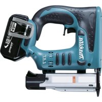
AN610H - Electric stapler MAKITA - Free user manual and instructions
Find the device manual for free AN610H MAKITA in PDF.

| Product type | Pneumatic stapler |
| Brand | Makita |
| Model | AN610H |
| Dimensions (L x W x H) | 282 mm x 136 mm x 277 mm |
| Net weight | 1.9 kg |
| Air pressure | 0.98 – 2.26 MPa (9.8 – 22.6 bar) |
| Max. recommended pressure | 2.26 MPa (22.6 bar) |
| Nail length | 32 mm – 65 mm (wire collated nails or strip nails) |
| Nail capacity (wire collated) | 250, 300 or 400 pieces |
| Nail capacity (strip) | 200 pieces |
| Min. hose diameter | 5.0 mm |
| Depth adjustment | Range 0 to 6 mm (0.8 mm per turn) |
| Safety system | Trigger + contact element (prevents accidental discharges) |
| Hook function | Rotatable hook for temporary hanging |
| Nose adapter | Protects the workpiece surface |
| Lubrication | Makita pneumatic tool oil (one drop every 30 nails or 2-3 drops before/after use) |
| Usable materials | Wood, sheet metal (≤2.3 mm), soft concrete |
| Maintenance | Drain the tool, clean with a blow bulb, store in a warm and dry place |
| Recommended accessories | Safety glasses, hearing protection, safety helmet |
Frequently Asked Questions - AN610H MAKITA
User questions about AN610H MAKITA
0 question about this device. Answer the ones you know or ask your own.
Ask a new question about this device
Download the instructions for your Electric stapler in PDF format for free! Find your manual AN610H - MAKITA and take your electronic device back in hand. On this page are published all the documents necessary for the use of your device. AN610H by MAKITA.
USER MANUAL AN610H MAKITA
GB Construction Nailer
Instruction Manual
F Clouese pour travaux de construction Manuel d'instructions
D Baunagler Betriebsanleitung
I Chiodatrice a bobina Istruzioni per l'uso
NL Nagelpistool voor bouwwerk Gebruiksaanwijzing
E Clavadora de clavos para la construccion Manual de instructaciones
P Pregador para construcao Manual de instruções
DK Konstruktionssompistol Brugsanvisning
GR Oikoboiokc kapwntnpac Odyicxpnoewc

AN610H
1

2

3

4
5

6

7
8
9
10

11 12
13 14

15 16
17 18
1920

21 22
23 24
25 26
Symbols
The followings show the symbols used for the tool. Be sure that you understand their meaning before use.
Symboles
Explanation of general view
1 Compressor air output per minute
2 Nailing frequency (times/min.)
3 A d j u s t e r
4 Shallow
5 D e e p
6 Too deep
7 F U S h
8 Too shallow
9 Ho o k
10 Hole
11 Protrusion
12 Nose adapter
13 Magazine cap
14 Latch lever
15 Door
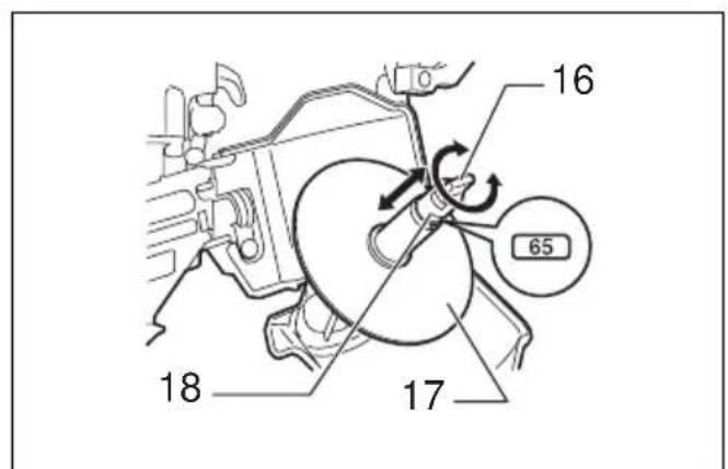
16 Adjustfit
17 Change plate
18 Arrow
19 Nail guide
20 Feeder
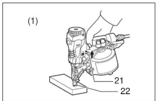
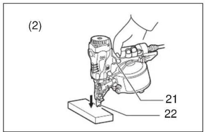
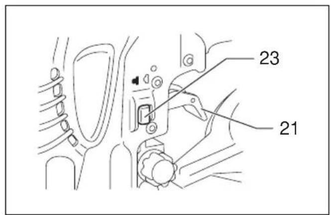
21 Trigger
22 Contact element
23 Change lever
24 0.7 mm or less thick for steel plate
25 Thickness of workpiece
26 10 mm or more
27 C-shaped steel
(Thickness 1.6mm - 2.3mm
28 Nail driven to a proper depth
29 Nail driven too deep will cause deformation of workpieces
30 Nail length
31 Wood thickness
32 Concrete range 10 - 15 mm
33 Small rod
34 Screwdriver
35 Cap
36 Drain cock
37 Air filter
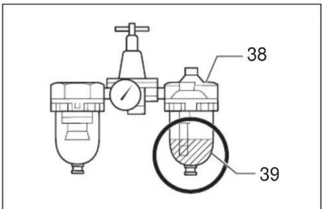
38 Oiler
39 Pneumatic oil
SPECIFICATIONS
| Model AN610H | |
| Air pressure 0.98 – 2.26 MPa (9.8 – 22.6 bar) | |
| Nail length | Wire-collated coil nail 32 mm – 65 mm Sheet-collated coil nail 32 mm – 65 mm |
| Nail capacity | Wire-collated coil nail 250 pcs, 300 pcs, 400 pcs Sheet-collated coil nail 200 pcs |
| Min. hose diameter 5.0 mm | |
| Dimensions (L x H x W) 282 mm x 27 | mm x 136 mm |
| Net weight 1.9 kg | |
- Due to our continuing program of research and development, the specifications herein are subject to change without notice.
- Note: Specifications may differ from country to country.
Intended use
The tool is intended for the preliminary interior work such as fixing floor joists or common rafters and framing work in 2 × 4 housing.
IMPORTANT SAFETY INSTRUCTIONS
ENB109-1
WARNING:
WHEN USING THIS TOOL, BASIC SAFETY PRECAUTIONS SHOULD ALWAYS BE FOLLOWED TO REDUCE THE RISK OF PERSONAL INJURY, INCLUDING THE FOLLOWING:
READ ALL INSTRUCTIONS.
- For personal safety and proper operation and maintenance of the tool, read this instruction manual before using the tool.
- Always wear safety glasses to protect your eyes from dust or nail injury.
WARNING:
It is an employer's responsibility to enforce the use of safety eye protection equipment by the tool operators and by other persons in the immediate working area.
- Wear hearing protection to protect your ears against exhaust noise and head protection. Also wear light but not loose clothing. Sleeves should be buttoned or rolled up. No necktie should be worn.
- Rushing the job or forcing the tool is dangerous. Handle the tool carefully. Do not operate when under the influence of alcohol, drugs or the like.
-
General Tool Handling Guidelines:
-
Always assume that the tool contains fasteners.
- Do not point the tool toward yourself or anyone whether it contains fasteners or not.
- Do not activate the tool unless the tool is placed firmly against the workpiece.
- Respect the tool as a working implement.
- No horseplay.
- Do not hold or carry the tool with a finger on the trigger.
- Do not load the tool with fasteners when any one of the operating controls is activated.
-
Do not operate the tool with any power source other than that specified in the tool operating/safety instructions.
-
An improperly functioning tool must not be used.
-
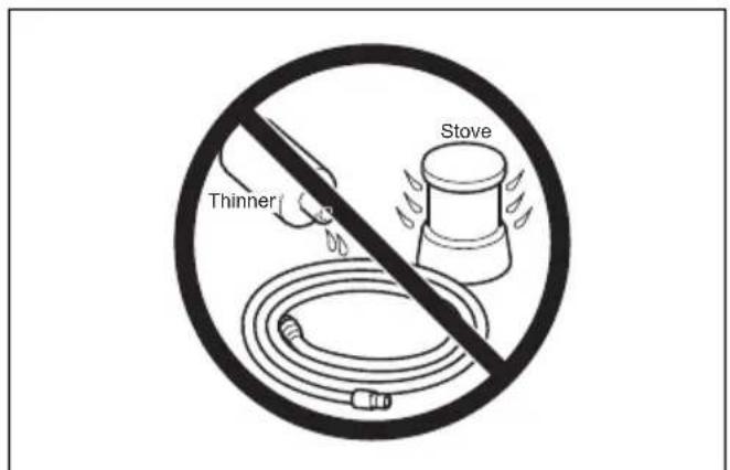
Sparks sometimes fly when the tool is used. Do not use the tool near volatile, flammable materials such as gasoline, thinner, paint, gas, adhesives, etc.; they will ignite and explode, causing serious injury.
-
The area should be sufficiently illuminated to assure safe operations. The area should be clear and litter-free. Be especially careful to maintain good footing and balance.
-
Only those involved in the work should be in the vicinity. Children especially must be kept away at all times.
-
There may be local regulations concerning noise which must be complied with by keeping noise levels within prescribed limits. In certain cases, shutters should be used to contain noise.
-
Do not play with the contact element: it prevents accidental discharge, so it must be kept on and not removed. Securing the trigger in the ON position is also very dangerous. Never attempt to fasten the trigger. Do not operate a tool if any portion of the tool operating controls is inoperable, disconnected, altered, or not working properly.
-
Operate the tool within the specified air pressure of 0.98 - 2.26MPa (9.8 - 22.6 bar) for safety and longer tool life. Do not exceed the recommended max. operating pressure of 2.26MPa (22.6 bar). The tool should not be connected to a source whose pressure potentially exceeds 3.39MPa (33.9 bar).
-
Make sure that the pressure supplied by the compressed air system does not exceed the maximum allowable pressure of the fastener driving tool. Set the air pressure initially to the lower value of the recommended allowable pressure (see SPECIFICATIONS).
-
Never use the tool with other than compressed air. If bottled gas (carbon dioxide, oxygen, nitrogen, hydrogen, air, etc.) or combustible gas (hydrogen, propane, acetylene, etc.) is used as a power source for this tool, the tool will explode and cause serious injury.
-
Always check the tool for its overall condition and loose screws before operation. Tighten as required.
-
Make sure all safety systems are in working order before operation. The tool must not operate if only the trigger is pulled or if only the contact arm is pressed against the wood. It must work only when both actions are performed. Test for possible faulty operation with nails unloaded and the pusher in fully pulled position.
-
Check walls, ceilings, floors, roofing and the like carefully to avoid possible electrical shock, gas leakage, explosions, etc. caused by striking live wires, conduits or gas pipes.
-
Use only nails specified in this manual. The use of any other nails may cause malfunction of the tool.
-
Never use fastener driving tools marked with the symbol "Do not use on scaffolds, ladders" for specific application for example:

- when changing one driving location to another involves the use of scaffoldings, stairs, ladders, or ladder alike constructions, e.g. roof laths;
- closing boxes or crates;
-
fitting transportation safety systems e.g. on vehicles and wagons.
-
Do not permit those uninstructed to use the tool.
- Make sure no one is nearby before nailing. Never attempt to nail from both the inside and outside at the same time. Nails may rip through and/or fly off, presenting a grave danger.
-
Watch your footing and maintain your balance with the tool. Make sure there is no one below when working in high locations, and secure the air hose to prevent danger if there is sudden jerking or catching.
-
On rooftops and other high locations, nail as you move forward. It is easy to lose your footing if you nail while inching backward. When nailing against perpendicular surface, nail from the top to the bottom. You can perform nailing operations with less fatigue by doing so.
- A nail will be bent or the tool can become jammed if you mistakenly nail on top of another nail or strike a knot in the wood. The nail may be thrown and hit someone, or the tool itself can react dangerously. Place the nails with care.
- Do not leave the loaded tool or the air compressor under pressure for a long time out in the sun. Be sure that dust, sand, chips and foreign matter will not enter the tool in the place where you leave it setting.
- Do not point the ejection port at anyone in the vicinity. Keep hands and feet away from the ejection port area.
- When the air hose is connected, do not carry the tool with your finger on the trigger or hand it to someone in this condition. Accidental firing can be extremely dangerous.
- Handle the tool carefully, as there is high pressure inside the tool that can be dangerous if a crack is caused by rough handling (dropping or striking). Do not attempt to carve or engrave on the tool.
- Stop nailing operations immediately if you notice something wrong or out of the ordinary with the tool.
-
Always disconnect the air hose and remove all of the nails:
-
When unattended.
- Before performing any maintenance or repair.
- Before cleaning a jam.
-
Before moving the tool to a new location.
-
Perform cleaning and maintenance right after finishing the job. Keep the tool in tip-top condition. Lubricate moving parts to prevent rusting and minimize friction-related wear. Wipe off all dust from the parts.
- Do not modify tool without authorization from Makita.
- Ask Makita's Authorized service centers for periodical inspection of the tool.
- To maintain product SAFETY and RELIABILITY, maintenance and repairs should be performed by Makita Authorized Service Centers, always using Makita replacement parts.
- Use only pneumatic tool oil specified in this manual.
- Never connect tool to compressed air line where the maximum allowable pressure of tool cannot be exceeded by 10% . Make sure that the pressure supplied by the compressed air system does not exceed the maximum allowable pressure of the fastener driving tool. Set the air pressure initially to the lower value of the recommended allowable pressure.
- Do not attempt to keep the trigger or contact element depressed with tape or wire. Death or serious injury may occur.
- Always check contact element as instructed in this manual. Nails may be driven accidentally if the safety mechanism is not working correctly.
SAVE THESE INSTRUCTIONS.
INSTALLATION
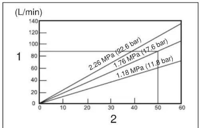
Selecting compressor (Fig. 1)
The air compressor must comply with the requirements of EN60335-2-34.
Select a compressor that has ample pressure and air output to assure cost-efficient operation. The graph shows the relation between nailing frequency, applicable pressure and compressor air output.
Thus, for example, if nailing takes place at a rate of approximately 50 times per minute at a compression of 1.76MPa (17.6 bar), a compressor with an air output over 90 liters/minute is required.
Pressure regulators must be used to limit air pressure to the rated pressure of the tool where air supply pressure exceeds the tool's rated pressure. Failure to do so may result in serious injury to tool operator or persons in the vicinity.
Selecting air hose (Fig. 2)
Use a high pressure resistant air hose.
Use an air hose as large and as short as possible to assure continuous, efficient nailing operation.
CAUTION:
- Low air output of the compressor, or a long or smaller diameter air hose in relation to the nailing frequency may cause a decrease in the driving capability of the tool.
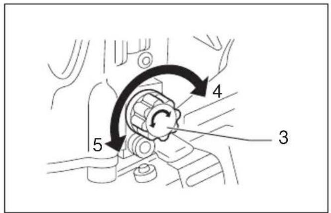
Lubrication
To insure maximum performance, install an air set (oiler, regulator, air filter) as close as possible to the tool. Adjust the oiler so that one drop of oil will be provided for every 30 nails. (Fig. 3)
When an air set is not used, oil the tool with pneumatic tool oil by placing 2 (two) or 3 (three) drops into the air fitting. This should be done before and after use. For proper lubrication, the tool must be fired a couple of times after pneumatic tool oil is introduced. (Fig. 4)
FUNCTIONAL DESCRIPTION
CAUTION:
- Always disconnect the hose before adjusting or checking function on the tool.
Adjusting the nailing depth (Fig. 5 & 6)
CAUTION:
- Always disconnect the hose before adjusting the depth of nailing.
If nail are driven too deep, turn the adjuster clockwise. If nail are driven too shallow, turn the adjuster counterclockwise.
The adjustable range is 0 - 6mm . (One full turn allows 0.8mm adjustment.)
Hook (Fig. 7)
CAUTION:
- Always disconnect the hose when hanging the tool using the hook.
- Never hang the tool on a waist belt or like. Dangerous accidental firing may result.
The hook is convenient for hanging the tool temporarily. This hook can be installed on either side of the tool.
When changing the installation position, remove the screw with a screwdriver. Install the hook on another side for installation and then secure it with the screw.
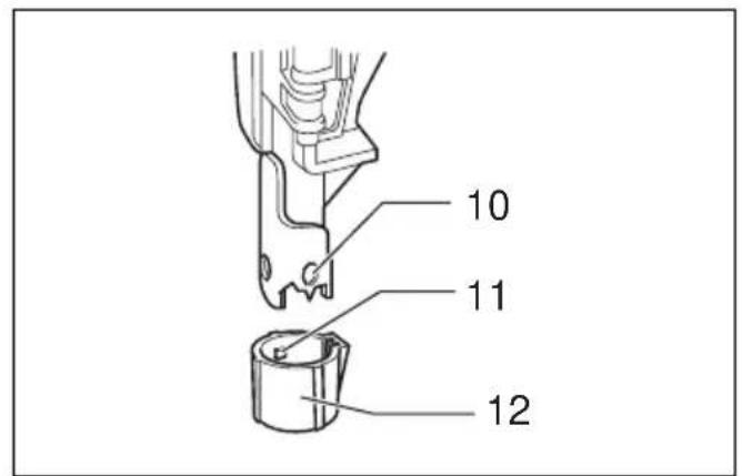
Use the nose adapter (Fig. 8)
CAUTION:
- Always disconnect the hose before installing or removing the nose adapter.
If you like to protect the surface of workpiece, attach the nose adapter of contact element.
When nailing workpieces with easily-marred surfaces, use the nose adapter. To attach the nose adapter to the contact element, press it onto the contact element until the protrusion in three places inside the nose adapter fit in three holes in the contact element.
ASSEMBLY
CAUTION:
- Always disconnect the air hose before loading the nailer.
Loading nailer
CAUTION:
- Make sure that the coil support plate is set to the correct step for used nails.
Disconnect the air hose from the tool.
Select nails suitable for your work. Depress the latch lever and open the magazine cap. (Fig. 9)
Lift and turn the coil support plate so that the arrow with nail size indicated on the coil support plate will point to the corresponding graduation increment marked on the magazine. If the tool is operated with the coil support plate set to the wrong step, poor nail feed or malfunction of the tool may result. (Fig. 10)
Place the nail coil over the coil support plate. Uncoil enough nails to reach the feed claw. Place the first nail in the driver channel and the second nail in the feed claw.
Place other uncoiled nails on feeder body. Close the magazine cap slowly until it lock after checking to see that the nail coil is set properly in the magazine. (Fig. 11)
Connecting air hose
Slip the air socket of the air hose onto the air fitting on the nailer. Be sure that the air socket locks firmly into position when installed onto the air fitting. A hose coupling must be installed on or near the tool in such a way that the pressure reservoir will discharge at the time the air supply coupling is disconnected.
OPERATION
CAUTION:
- Make sure all safety systems are in working order before operation.
- To drive a nail, you may place the contact element against the workpiece and pull the trigger, or
- Pull the trigger first and then place the contact element against the workpiece. (Fig. 12 & 13)
- No. (1) method is for intermittent nailing, when you wish to drive a nail carefully and very accurately. No. (2) method is for continuous nailing.
CAUTION:
However when the tool is set to the "Intermittent Nailing" mode, WITH THE TRIGGER HELD IN A HALF-PULLED POSITION, an unexpected nailing could occur, if contact element is allowed to re-contact against the workpiece or the other surface under the influence of recoil.
In order to avoid this unexpected nailing, perform as follows:
A. Do not place the contact element against the workpiece with excessive force.
B. Pull the trigger fully and hold it on for 1 - 2 seconds after nailing.
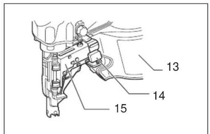
- For No. (1) method, set the change lever to the position.

- For No. (2) method, set the change lever to the position.

After using the change lever to change the nailing method, always make sure that the change lever is properly set to the position for the desired nailing method. (Fig. 14 & 15)
Nailing of steel plate (Fig. 16 & 17)
WARNING:
- Use 2.3mm or less steel for C-shaped one.
The tool will bounce severely and a nail struck back, causing serious injuries. - Use hardened nails only for steel plate.
Using other purported nails may cause serious injuries. - When nailing, hold the tool so that it stands upright to the driving surface.
Slanted nailing may cause nails to strike back, causing serious injuries.
- When fastening a corrugated zinc plate on the C-shaped steel, use 0.7mm or less thick plate and 32mm long hardened nails. Failure to do so may cause nails to strike back, causing serious injuries.
- Do not use the tool for nailing on ceiling or roof.
Choose and use nails more than 10mm longer than total thickness of all workpiece to be fastened by referring to the table below.
| Material thickness (mm) Nail length (mm) | |
| 1.8 – 22 32 | |
| 10 – 27 38 | |
| 15 – 30 45 | |
| 15 – 38 50 | |
CAUTION:
- Depending on the hardness and total thickness of all workpiece in combination to be fastened, enough fastening may not be obtained. Nailing on steel plate to excessive depth may extremely reduce the fastening force. Before nailing, adjust the nailing depth properly.
- In the nailing on the steel plate, the driver may be clogged due to susceptibility to wear. When it is worn, sharpen it or replace it with a new one.
Nailing of concrete (Fig. 18)
WARNING:
- Use hardened nails only for concrete.
- Using other purported nails may cause serious injuries. Do not nail directly on the concrete or do not use to fasten directly the steel plate to the concrete. Failure to do so may cause concrete fragments to fly off or nails to strike back, causing serious injuries.
- When nailing, hold the tool so that it stands upright to the driving surface. Slanted nailing may cause concrete fragments to fly off or nails to strike back, causing serious injuries.
- Do not use on the surface that objects hang from, such as area where hangers for sewer pipe, dust pipe etc. are set up.
Choose and use nails so that the penetration amount into concrete ranges 10mm - 15mm by referring to the table below.
| Wood thickness (mm) | Nail length (mm) | Concrete (mm) |
| 20 32 Approx. 12 | ||
| 25 38 Approx. 13 | ||
| 30 45 Approx. 15 | ||
| 35 50 Approx. 15 | ||
CAUTION:
- Use this tool only for soft concrete built up not so long before. Using on the hard concrete may cause nail bending or nailing to insufficient depth.
- When the penetration amount into concrete comes to more than 15mm , nailing to the sufficient length may not be obtained.
Cutting off the sheet (Fig. 19)
CAUTION:
- Always disconnect the hose before cutting off the sheet.
Tear off the output sheet in the direction of the arrow when using the sheet collated nails.
MAINTENANCE
CAUTION:
- Always disconnect the air hose from the tool before attempting to perform inspection or maintenance.
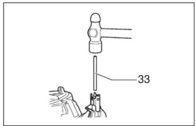
Jammed nailer (Fig. 20 & 21)
CAUTION:
- Always disconnect the air hose and remove the nails from the magazine before cleaning a jam.
When the nailer becomes jammed, do as follows:
Open the magazine cap and remove the nail coil. Insert a small rod or the like into the ejection port and tap it with a hammer to drive out the nail jamming from the ejection port. Reset the nail coil and close the magazine cap.
Drain tool
Remove the hose from the tool. Place the tool so that the air fitting faces down to the floor. Drain as much as possible.
Cleaning of tool
Iron dust that adhere to the magnet can be blown off by using an air duster.
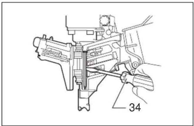
Cap (Fig. 22)
When not in use, disconnect the hose. Then cap the air fitting with the cap.
Storage
When not in use, the nailer should be stored in a warm and dry place.
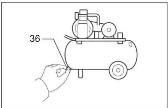
Maintenance of compressor, air set and air hose
After operation, always drain the compressor tank and the air filter. If moisture is allowed to enter the tool, it may result in poor performance and possible tool failure.
(Fig. 23 & 24)
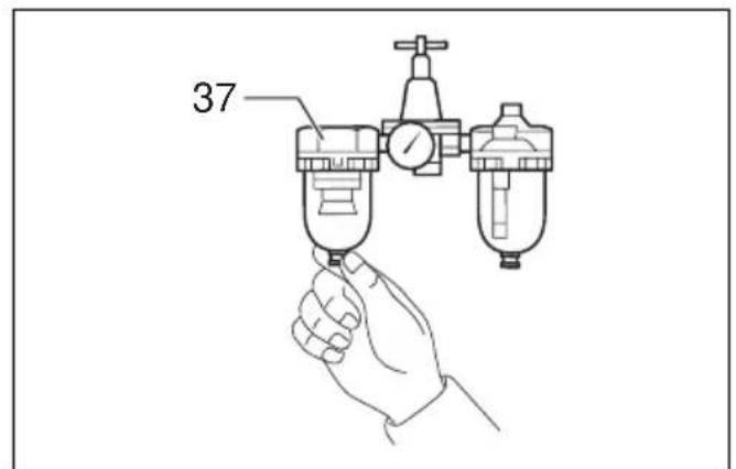
Check regularly to see if there is sufficient pneumatic oil in the oiler of the air set. Failure to maintain sufficient lubrication will cause O-rings to wear quickly. (Fig. 25)
Keep the air hose away from heat (over 60ircC , over 140ircF ), away from chemicals (thinner, strong acids or alkalis). Also, route the hose away from obstacles which it may become dangerously caught on during operation.
Hoses must also be directed away from sharp edges and areas which may lead to damage or abrasion to the hose.
(Fig. 26)
To maintain product SAFETY and RELIABILITY, repairs, any other maintenance or adjustment should be performed by Makita Authorized Service Centers, always using Makita replacement parts.
ACCESSIONS
CAUTION:
- These accessories or attachments are recommended for use with your Makita tool specified in this manual. The use of any other accessories or attachments might present a risk of injury to persons. Only use accessory or attachment for its stated purpose.
If you need any assistance for more details regarding these accessories, ask your local Makita service center.
Nails
Air hoses
- Safety goggles
FRANÇAIS
Descriptif
Anootpayyian epyaIeiou
ApaipoeToe 1aotko oWnva ano to epyaleio. TonoetnoTe to epyaleio wote o ouvdeos aepa va eivai otpauevoc npoc to edaoc. Anootpayiote oo to duvatov nepiaooTepo.
Kaapiooεpyaλεiou
Mnpoeite va aphipeoet en oKovn oipou nou npookoaaatai 0to mayvntn xpnaonoiwvtas unxavna aphiepoc nC oKovnc e Emuan an aepa.
Kanaki (Eik. 22)
Otauev xpnouoite to epyaia, aapieotetov 204060wna. Akoaou8wC kaUpsiTe to ouv0e0o aepa u Kaaki.
Φuλαη
Otauovxnpoimonoitei,0kapwntipac8a npentvaouaaotai e 2e0to kai oteyvoo.
Suvntnpn ouumieotn, ouvoloaepoc kai oWlambdaeepoc
Meta tny aeitoupyia navtoe otpayyizte to doxio tou oumuieotn kai to iItpo aepoc. Eav uypaia eolaeoi oTo epyaiaio, mnpei va exi w anotelaa kaan ano0on kai niavn β λ αβ η tou epyaiaou. (Eik. 23 KAI 24)
Eéyεεtakiká va δεitε εav unapxεi apkεt òaio εpyaλεiou πειεμevou aεpa στov λiavtn Tou ouvólou aεpa. Aéλεia va δiatnpnoεte εnapkn λiavon θa npokaloei tnv γρηyopn Φθopa twδaktuωv O.(Eik.25)
Kpatate tov oWnva aepoc paua ano zoeotn (unepavw 60ircC unepavw 140ircF ), paqua ano xmuka (biautec, ioupa oEa n alkaiká). Enionc, dEvuveTe tov oWnva paqua ano eunoda oTa onoi 8a mnpouoe va eunlambdae i enikivduva kata tvv Ieitoupyia.
Oi ω λ ην npenla δi uθoν t a paKpua ano aixunpec akpckai nepioxoc nou nOpEi va odnynouov 0e zmuia n Ekoepoc tou oWnva. (Eik. 26)
EC-DECLARATION OF CONFORMITY
Model; AN610H
We declare under our sole responsibility that this product is in compliance with the following standards of standardized documents;
EN792 in accordance with Council Directives, 98/37/EC.
FRANÇAISE
DECLARATION DE CONFORMITE CE
Modèle ; AN610H
Michigan Drive, Tongwell, Milton Keynes, Bucks MK15 8JD, ENGLAND
PORTUGUES
DECLARATION DE CONFORMIDADE DA CE
Modelo; AN610H
Declaramos sob inteira responsabilitad que este produits obedece as segunte normas de documents normalizados;
EU-DEKLARATION OM KONFORMITET
Model; AN610H
Michigan Drive, Tongwell, Milton Keynes, Bucks MK15 8JD, ENGLAND
ENGLISH
For European countries only
Noise and Vibration
The typical A-weighted noise levels are sound pressure level: 86 dB (A) sound power level: 99 dB (A)
- Wear ear protection. -
The typical weighted root mean square acceleration value is 3m / s2
These values have been obtained according to EN792.
FRANÇAISE
Movi yia xwpe Tnc Eupwnns
OpuockaiKpaagoo
OitunikcA-μεtpoouevεεvtadεicxou evat πεon nXou:86dB (A) δuvaum tou nXou:99 dB (A) -Φopate wtoaonidεc.-
H turikn aia tnc μετρομενns piac₂tou μεoou tεtpayovou nnc enitaxuvong εival 3m/s
Autec oituiéc exouv onuieiwoe i ouphiwa u EN792.
Makita Corporation
Anjo, Aichi, Japan
- 26
- Symbols
- Symboles
- Explanation of general view
- SPECIFICATIONS
- Intended use
- IMPORTANT SAFETY INSTRUCTIONS
- WARNING:
- READ ALL INSTRUCTIONS.
- SAVE THESE INSTRUCTIONS.
- INSTALLATION
- Selecting compressor (Fig. 1)
- Selecting air hose (Fig. 2)
- CAUTION:
- Lubrication
- FUNCTIONAL DESCRIPTION
- Adjusting the nailing depth (Fig. 5 & 6)
- Hook (Fig. 7)
- Use the nose adapter (Fig. 8)
- ASSEMBLY
- Loading nailer
- Connecting air hose
- OPERATION
- Nailing of steel plate (Fig. 16 & 17)
- Nailing of concrete (Fig. 18)
- Cutting off the sheet (Fig. 19)
- MAINTENANCE
- Jammed nailer (Fig. 20 & 21)
- Drain tool
- Cleaning of tool
- Cap (Fig. 22)
- Storage
- Maintenance of compressor, air set and air hose
- (Fig. 23 & 24)
- (Fig. 26)
- ACCESSIONS
- FRANÇAIS
- Descriptif
- Anootpayyian epyaIeiou
- Kaapiooεpyaλεiou
- Kanaki (Eik. 22)
- Φuλαη
- Suvntnpn ouumieotn, ouvoloaepoc kai oWlambdaeepoc
- EC-DECLARATION OF CONFORMITY
- Model; AN610H
- FRANÇAISE
- DECLARATION DE CONFORMITE CE
- Modèle ; AN610H
- PORTUGUES
- DECLARATION DE CONFORMIDADE DA CE
- EU-DEKLARATION OM KONFORMITET
- ENGLISH
- For European countries only
- Noise and Vibration
- Movi yia xwpe Tnc Eupwnns
- OpuockaiKpaagoo
- Makita Corporation
Brand : MAKITA
Model : AN610H
Category : Electric stapler