SinePower MSI2312T - Camping WAECO - Free user manual and instructions
Find the device manual for free SinePower MSI2312T WAECO in PDF.

Frequently Asked Questions - SinePower MSI2312T WAECO
User questions about SinePower MSI2312T WAECO
0 question about this device. Answer the ones you know or ask your own.
Ask a new question about this device
Download the instructions for your Camping in PDF format for free! Find your manual SinePower MSI2312T - WAECO and take your electronic device back in hand. On this page are published all the documents necessary for the use of your device. SinePower MSI2312T by WAECO.
USER MANUAL SinePower MSI2312T WAECO
natural_image
Technical line drawing of an electronic device chassis with ports and connectors (no text or symbols)SinePower MSI2312T, MSI3512T, MSI2324T, MSI3524T
Installation and Operating Manual
text_image
Technical diagram showing three labeled components of an electronic device: power, socket, and plug wires.2
text_image
25 cm 25 cm3
natural_image
Technical diagram showing a pencil inserted into a component with a curved arrow indicating rotation (no text or symbols present)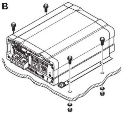
natural_image
Isometric line drawing of an electronic device with labeled ports and connectors (no text or symbols present)4
text_image
Technical diagram of an electronic device showing labeled components including power input, cable, and terminal connections.5
text_image
2 3 4 1 ON OFF RESET BREAKER 5 6 7 14 13 1112 10 9 OUTPUT INPUT
flowchart
graph TD
    A["Input 230 V AC"] --> B["N PE L1"]
    B --> C["MSI DC 230 V AC"]
    C --> D["FI 2 RCD"]
    D --> E["Output 230 V AC"]
    F["Input DC"] --> G["MSI DC 230 V AC"]
    G --> H["FI 1 RCD"]
    H --> I["Output 230 V AC"]
    J["FE L1"] --> K["Output 230 V AC"]
    L["FE L1"] --> M["Output 230 V AC"]
    N["FE L1"] --> O["Output 230 V AC"]
    P["FE L1"] --> Q["Output 230 V AC"]
    R["FE L1"] --> S["Output 230 V AC"]
    T["FE L1"] --> U["Output 230 V AC"]
    V["FE L1"] --> W["Output 230 V AC"]
    X["FE L1"] --> Y["Output 230 V AC"]
    Z["FE L1"] --> AA["Output 230 V AC"]
7
text_image
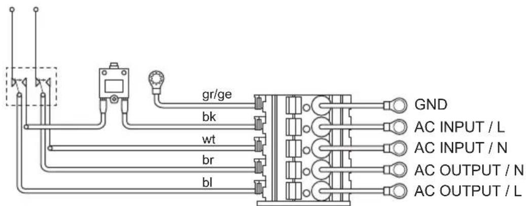
gr/ge bk wt br bl GND AC INPUT / L AC INPUT / N AC OUTPUT / N AC OUTPUT / L| L | N | N | L |  GND GND |
| ACOUTPUT | ACINPUT | |||
8

flowchart
graph TD
    A["ENB"] --> B["ON:INV."]
    C["GND"] --> D["OFF:INV."]
    B --> E["ON"]
    D --> F["OFF"]
9

text_image
ENB TR HI:INV. → ON (TR ON) LOW:INV.→ OFF (TR OFF)10
text_image
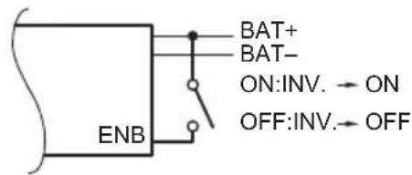
BAT+ BAT- ON:INV. → ON OFF:INV.→ OFF ENB11
text_image
ON:INV. → ON OFF:INV. → OFF ENB + - GND DC POWER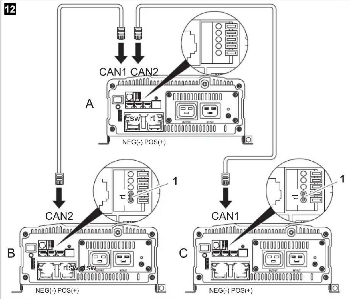
flowchart
graph TD
    A["Device A"] -->|CAN1 CAN2| B["Switch"]
    B -->|CAN2| C["Device B"]
    C -->|CAN1| D["Switch"]
    D -->|CAN1| E["Device C"]
    style A fill:#f9f,stroke:#333
    style B fill:#ccf,stroke:#333
    style C fill:#cfc,stroke:#333
    style D fill:#fcc,stroke:#333
    style E fill:#cff,stroke:#333
13
natural_image
Technical line drawing of a dual-flower cooling fan assembly (no text or symbols)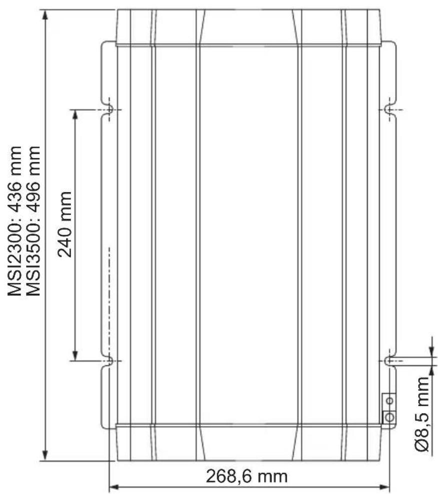
text_image
MSI2300: 436 mm MSI3500: 496 mm 240 mm Ø8,5 mm 268,6 mm
natural_image
Pure technical line drawing of a rectangular panel or enclosure with internal grid lines and mounting holes (no text or symbols)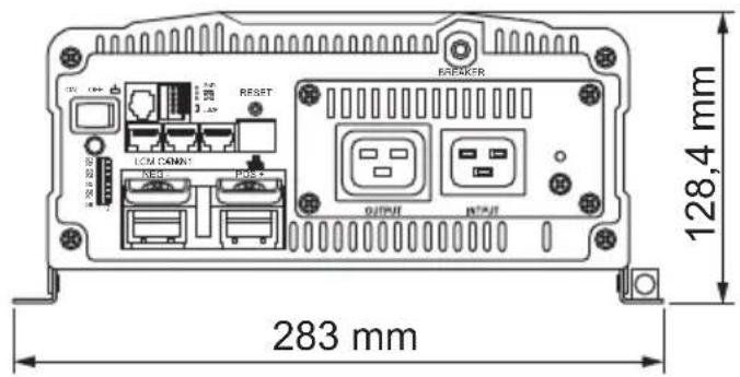
text_image
128,4 mm 283 mmPlease read this instruction manual carefully before installation and first use, and store it in a safe place. If you pass on the product to another person, hand over this instruction manual along with it.
Table of contents
1 Explanation of symbols 35
2 General safety instructions 35
3 Scope of delivery 37
4 Accessories 38
5 Target group for this manual 38
6 Intended use 38
7 Technical description 39
8 Fitting the inverter 42
9 Connecting the inverter 43
10 Using the inverter....49
11 Cleaning and caring for the inverter....52
12 Troubleshooting 52
13 Warranty 53
14 Disposal 53
15 Technical data .... 54
1 Explanation of symbols

WARNING!
Safety instruction: Failure to observe this instruction can cause fatal or serious injury.

NOTICE!
Failure to observe this instruction can cause material damage and impair the function of the product.

NOTE
Supplementary information for operating the product.
▶ Action: This symbol indicates that action is required on your part. The required action is described step-by-step.
√This symbol describes the result of an action.
Fig. 1 5, page 3: This refers to an element in an illustration. In this case, item 5 in figure 1 on page 3.
2 General safety instructions
2.1 General safety
The manufacturer accepts no liability for damage in the following cases:
● Faulty assembly or connection
● Damage to the product resulting from mechanical influences and excess voltage
- Alterations to the product without express permission from the manufacturer
● Use for purposes other than those described in the operating manual

WARNING!
- Only use the device as intended.
- Do not operate the device in a damp or wet environment.
-
Do not operate the device near any flammable materials.
-
Do not operate the device in areas that are potentially explosive.
● Maintenance and repair work may only be carried out by qualified personnel who are familiar with the risks involved and the relevant regulations. - People (including children) whose physical, sensory or mental capacities or whose lack of experience or knowledge prevent them from using this product safely should not use it without the supervision or instruction of a responsible person.
● Electrical devices are not toys
Always keep and use the device out of the reach of children.
2.2 Safety when installing the device

WARNING!
- Installing the device may only be performed by qualified personnel who are familiar with the guidelines and safety precautions to be applied.
- If electrical devices are incorrectly installed on boats, corrosion damage might occur. The device should be installed by a specialist (marine) electrician.

NOTICE!
● Ensure that the device is standing firmly.
The device must be set up and fastened in such a way that it cannot tip over or fall down.
- Do not expose the device to a heat source (such as direct sunlight or heating). Avoid additional heating of the device in this way.
- If cables have to be fed through metal walls or other walls with sharp edges, use ducts or tubes to prevent damage.
- Do not lay cables which are loose or bent next to electrically conductive material (metal).
- Do not pull on the cables.
- Do not lay the 230 V mains cable and the 12/24 V DC cable in the same duct.
- Fasten the cables securely.
- Lay the cables so that they cannot be tripped over or damaged.
2.3 Operating the device safely

WARNING!
- Operate the device only if you are certain that the housing and the cables are undamaged.
- Even after the fuse triggers, parts of the inverter remain live.
● Always disconnect the power supply when working on the device.

NOTICE!
● Make sure the air inlets and outlets of the device are not covered.
- Ensure good ventilation. The inverter produces dissipated heat which has to be diverted.
- Do not connect the 230 V output of the inverter (fig. 5 7, page 4) to a different 230 V source.
3 Scope of delivery
No. in fig. 1, Designation page 3
| 1 Sine wave inverter |
| 2 Connection cable with safety coupling(for 230 V~ output) |
| 3 Connection cable with safety plug(for 230 V~ supply) |
| - Operating manual |
4 Accessories
Designation Item no.
Remote control MCR-7
Remote control MCR-9
5 Target group for this manual

WARNING!
The electrical installation (chapter “Connecting the inverter” on page 43) is intended for professionals who are familiar with the applicable regulations of the country in which the equipment is to be installed and/or used.
6 Intended use

WARNING!
Never use the inverter on vehicles where the positive terminal of the battery is connected to the chassis.
The wave inverter converts direct current of
● 12 V== (MSI2312T, MSI3512T)
● 24 V== (MSI 2324T, MSI3524T)
into a 200 – 240 V AC supply of 50 Hz or 60 Hz.
7 Technical description
The inverters can be operated wherever
- a 12 V== connection (MSI2312T, MSI3512T)
● a 24 V== connection (MSI2324T, MSI3524T)
is available. The light-weight and compact construction of this device allows for easy installation in mobile homes, commercial vehicles or motor and sailing yachts.
The output voltage corresponds to the household voltage from the socket (pure sine wave, THD < 3%).
Please observe the values for constant output power and peak output power as indicated in chapter "Technical data" on page 54. Never connect devices that have a higher power requirement.

NOTE
Note when connecting devices with an electrical drive (such as power drills and refrigerators), that they often require more power than is indicated on the type plate.
The inverter has various protective mechanisms.
- Overvoltage shutdown: The inverter shuts itself off when the voltage exceeds the cut-off value. It restarts when the voltage returns to the restart value.
- Undervoltage shutdown: The inverter shuts itself off when the voltage sinks below the cut-off value. It restarts when the voltage rises to the re-start value.
- Excess temperature shutdown: The inverter switches off when the temperature inside the device or the temperature on the cooling element exceeds a cut-off value. It restarts when the voltage rises to the restart value.
- Overloading and short circuit shutdown: The LED on the inverter indicates an operating fault (constant red light) when an excess load is connected or a short circuit has occurred. The fuse in the device must be pressed in again by hand after it is triggered by excess current.
- Incorrect polarity protection: The incorrect polarity protection prevents the wrong polarity when connecting the inverter.

NOTE
The individual values are found in the chapter "Technical data" on page 54.
The inverters have a 230 V\~ socket and a connection terminal for permanent connection.
Due to the voltage synchronisation with the AC input voltage, the inverter is suitable for operating sensitive consumers which react to an irregular voltage supply.
The device can also be configured with a PC via an RS 232 interface and using the DIP switches on the device.
The inverter can be switched to an energy-saving mode to prevent the connected battery from discharging too quickly.
Parallel operation allows up to three inverters (of the same model) to run at the same time.
The inverter can be easily controlled using the remote control (accessory).
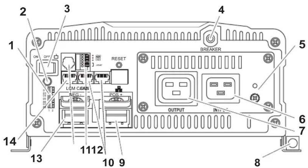
7.1 Control elements
Control elements of the inverter (fig. 5, page 4)
| Item Description Description | |
| 1 Dip switch Makes settings on the inverter (such as mains voltage, mains frequency, energy-saving mode). | |
| 2 LED See chapter “Status indications” on page 49 | |
| 3 Main switch“ON/OFF/REMOTE” switch: | Switches the device on, off or to operation via the remote control (accessory) |
| 4 Fuse Protects the inverter from overload.The fuse can be pressed in again once it has triggered. | |
| 5 Grounding screw Sets or removes the grounding bridge | |
7.2 Connections
Connections of the inverter (fig. 5, page 4)
| Item Description Description | |
| 6 AC input 230 V~ input jack | |
| 7 AC output 230 V~ output jack | |
| 8 Earth terminal Earthing on the vehicle body-work | |
| 9 POS+ Positive terminal | |
| 10 CAN1 and CAN2 port CAN BUS connections | |
| 11 Green terminal Setup of remote switch and parallel operation | |
| 12 RS232 port, REMOTE port | Connection of a PC using a serial RS232 interface or connection of the MCR-7 or MCR-9 remote control |
| 13 NEG– Negative terminal | |
| 14 LCM | Remote control connection |
8 Fitting the inverter
8.1 Tools required
For the electrical connection you will need the following tools:
- Crimping tool
- 3multi-coloured, flexible connection cables. Determine the necessary thickness from the table in chapter “Connecting the inverter” on page 43.
● Cable lugs and conductor sleeves
For fastening you will require the following tools:
● Machine bolts (M4) with washers and self-locking nuts or
● self-tapping screws or wood screws.
8.2 Mounting instructions
When selecting the installation location, observe the following instructions:
● The inverter can be mounted horizontally or vertically.
● The inverter must be installed in a place that is protected from moisture.
● The inverter may not be installed in the presence of flammable materials.
● The inverter may not be installed in a dusty environment.
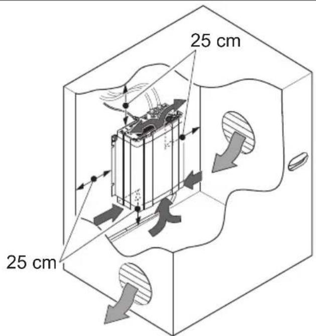
- The place of installation must be well ventilated. A ventilation system must be available for installations in small, enclosed spaces. The minimum clearance around the inverter must be at least 25 cm (fig. 2, page 3).
- The air intake on the underside or the air outlet on the back of the inverter must remain clear.
- For ambient temperatures higher than 50 °C (such as in engine or heating compartments, or direct sunlight), the heat from the inverter under load can lead to automatic shutdown.
● The device must be installed on a level and sufficiently sturdy surface.

NOTICE!
Before drilling any holes, make sure that no electrical cables or other parts of the vehicle can be damaged by drilling, sawing and filing.
8.3 Mounting the inverter
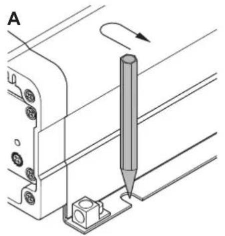
▶Hold the inverter against the installation location and mark the fastening points (fig. 3 A, page 4).
▶ Attach the inverter using your chosen fastening method (fig. 3 B, page 4).
9 Connecting the inverter
9.1 General instructions

WARNING!
- The inverter may only be connected by a qualified workshop. The following information is intended for technicians who are familiar with the guidelines and safety precautions to be applied.
- Never use the inverter on vehicles where the positive terminal of the battery is connected to the chassis.
-
If you do not fit a fuse to the positive cable, the cables can overload, which might result in a fire.
-
When installed in vehicles or boats, the inverter must be connected to the chassis or earth.
- When setting up a socket distribution circuit (mains setup), comply with the applicable regulations.
- Only use copper cables.
- Keep the cables as short as possible (< 1 m).
- Keep to the specified cable cross section and fit a cable fuse (fig. 4 3, page 4) as close to the battery as possible on the positive cable (see the table).
| Device | Required cable cross section | Cable fuse (fig. 4 3, page 4) |
| MSI2312T 70 mm ^2 350 A | ||
| MSI2324T 50 mm ^2 175 A | ||
| MSI3512T 95 mm ^2 400 A | ||
| MSI3524T 70 mm ^2 200 A |
9.2 Connecting the inverter to the battery

NOTICE!
Make sure that you do not reverse the polarity. Incorrect polarity can damage the inverter.

NOTE
Tighten the nuts and bolts to a maximum torque of 15 Nm. Loose connections may cause overheating.
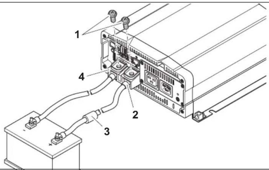
▶ Set the main switch (fig. 5 3, page 4) to "OFF".
▶ Loosen the screw (fig. 4 1, page 4) from the red positive terminal (fig. 4 2, page 4).
▶ Push the cable lug (fig. 4 2, page 4) of the positive cable into the red positive terminal and fasten it with the bolt.
▶ Connect the negative cable to the black negative cable (fig. 4 4, page 4).
▶Lay the positive cable from the inverter to the positive terminal of the vehicle battery and connect it.
▶ Lay the negative cable from the inverter to the negative terminal of the vehicle battery and connect it. A small spark can occur if the capacitors are being charged in the inverter.
▶ Connect the earth terminal (fig. 5 8, page 4) to the vehicle chassis.
9.3 Connecting the 230 V power cable
▶ Connect the 230 V\~ connection cable with safety plug (fig. 1 3, page 3) to the 230 V\~ input jack (fig. 5 6, page 4).
▶ Connect the safety plug to the 230 V\~ mains.
9.4 Connecting the 230 V output cable

WARNING!
Before connecting the 230 V\~ output cable, make sure the inverter is switched off at the main switch.
▶ Connect the 230 V\~ connection cable with safety plug (fig. 1 2, page 3) to the 230 V\~ output jack (fig. 5 7, page 4).
9.5 Connect multiple appliances
The device is equipped at delivery with galvanic isolation. For the safe operation of multiple appliances, it is essential that a circuit breaker (residual current circuit breaker) is built into the socket distribution circuit, see sample circuit diagram in fig. 6, page 5.
Sample circuit diagram legend:
| No. in fig. 6, Explanation page 5 |
| 1 230 V~ power source |
| 2 additional devices, e.g. battery charger, refrigerator |
| 3 DC power source (battery) |
| 4 Inverter |
| 5 Set grounding bridge (At delivery: not set, shown by dotted line) |
| 6 Circuit breaker (residual current circuit breaker) |
| 7 Socket distribution circuit for appliances |

WARNING! Danger of electrocution!
If you wish to connect more than one appliance to the inverter and install a socket distribution circuit, you must arrange a circuit breaker (residual current circuit breaker) and set a grounding bridge in the inverter.
▶ Install a residual current circuit breaker in the socket distribution circuit.
9.6 Setting the earthing bridge (fig. 5 5, page 4)
▶Remove the earthing screw from the bottom hole.
▶Screw the screw into the top hole.
9.7 Connecting the MCR-7 or MCR-9 remote control (accessory)

NOTICE!
- Only plug in the connection to the remote control in the remote port. The device can be damaged by connecting it incorrectly.
- Ensure that the remote control and inverter are supplied with the same input voltage.
- Follow the instruction manual of the remote control.
▶ Connect the remote control (accessory) to the remote port (fig. 5 12, page 4).
9.8 Connect external switch to turn device on and off

NOTE
Use cables with a cable cross section of 0.25 – 0.75 mm ^4 .
You can use the following as an external switch:
● external switch, voltage supply from the inverter: fig. 8, page 6
● Control unit with relay or transistor circuit (TR): fig. 9, page 6
● external switch with voltage supply from the battery (BAT) of the vehicle: fig. 10, page 6
● external switch with its own voltage supply (DC POWER) e.g. from the ignition: fig. 11, page 6
▶ Set the main switch (fig. 5 3, page 4) to "OFF" and make sure that the connection for the remote control (fig. 5 12, page 4) is not assigned.
▶ Set the main switch (fig. 5 3, page 4) to "REMOTE".
▶Connect the external on/off switch with the connection cable to the green terminal (fig. 5 11, page 4).
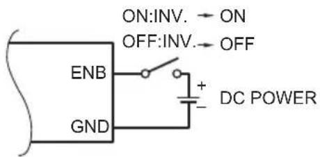
9.9 Connecting parallel operation

NOTICE!
- Use a cable with a cross section of 0.25 – 0.75 mm ^2 for connecting to the terminals for parallel operation.
- Parallel operation can only be set up using the same models (same item number).
● A maximum of three inverters can be operated in parallel. - The inverters operating in parallel must have the same settings for mains voltage and mains frequency. (see chapter "Configuring the inverter" on page 50.
▶ Set the main switch (fig. 5 3, page 4) to "OFF".
▶ Connect the inverter according to the sample circuit diagram (fig. 12, page 7).
In particular, make sure that the bridges for parallel operation are set correctly:
- Bridge removed (fig. 12 1, page 7) for inverter A and set for inverter B and C.

NOTE
The first inverter which is switched on after installing parallel operation is the master.
9.10 Pin assignment

NOTE
Keep the cable lengths as short as possible (<10 m), so there is no loss in the signal transmission.
The pins of the RS232 ports are assigned as follows:
| Inverter Computer | |||
| Pin Description | Description | Pin | |
| 1 Not assigned | Not assigned | 1 | |
| 2 | G | N | D |
| 3 | R | X | D |
| 4 | T | X | D |
| 5 Not assigned | Not assigned | ||
| 6 Not assigned | Not assigned | ||
The pins of the remote control connection are assigned as follows:
| Inverter | Remote control | |
| Pin | Description | Pin |
| 1 | CANH | 1 |
| 2 | CANL | 2 |
| 3 | PON | 3 |
| 4 | VCC- | 4 |
| 5 | VCC+ | 5 |
| 6 | DIS | 6 |
| 7 | 5VS- | 7 |
| 8 | 5VS+ | 8 |
10 Using the inverter
10.1 Switching on the inverter
▶ Set the main switch (fig. 5 3, page 4) of the inverter to the "ON" position. Set the On/Off switch to "OFF" to switch off.
The inverter performs a self-test.
During the self-test, the built-in speaker emits tones and the LED flashes.
√ After the self-test is completed successfully, the LED lights up green (fig. 5 2, page 4).
10.2 Status indications
The LED (fig. 5 2, page 4) shows the operating condition of the inverter.
Display Input voltage
| Green, constantly lit Normal mode | |
| Green, slow flash Energy-saving mode | |
| Orange, quick flash Input voltage too high | |
| Orange, slow flash Input voltage too low | |
| Red, double flash Inverter overheated | |
| Red, quick flash | Overvoltage |
| Red, slow flash | Undervoltage |
| Red, constantly lit | Overload |
| Red, slow flash + double flash | Fan fault |
The inverter switches off if:
- the battery voltage drops below 10 V (12 V--- connection) or 20 V (24 V--- connection),
- the battery voltage exceeds 16 V (12 V--- connection) or 32 V (24 V--- connection),
● the inverter overheats.
▶ If this happens, shut down the inverter with the main switch (fig. 5 3, page 4).
▶ Check that the inverter is sufficiently ventilated and that the ventilation grilles are unimpeded.
▶Wait 5 – 10 minutes and switch the inverter on again without any electric consumers.
When operating the inverter at high load for lengthy periods, it is advisable to start the engine in order to recharge the vehicle battery.
10.3 Configuring the inverter
You can adjust the device using the DIP switch (fig. 5 1, page 4).
Setting the mains voltage
You can set the mains voltage using the S1 and S2 dip switches.
| DIP switch | |
| Mains voltage S1 S2 | |
| 200 V Off Off | |
| 220 V On Off | |
| 230 V Off On | |
| 240 V On On |
Setting the mains frequency

WARNING! Danger of electrocution
Only adjust the S3 DIP switch when the respective frequency for the output voltage should be used.
You can set the mains frequency using the S3 dip switch.
| DIP switch | |
| Net frequency S3 | |
| 50 Hz Off | |
| 60 Hz On | |
Switching to energy-saving mode
You can set the energy-saving mode using the S4, S5 and S6 dip switches. In this way, the battery you connect to the inverter is not discharged as quickly.
The inverter operates in energy-saving mode as long as the required power is below the set level. If the required power exceeds the set level, the inverter works in normal mode.
The values to be set on your inverter can be found in the following table:
| Energy-saving mode | DIP switch |
| S4 S5 S6 | |
| Off Off Off Off | |
| 2% On Off Off | |
| 3% Off On Off | |
| 4% On On Off | |
| 5% Off Off On | |
| 6% On Off On | |
| 7% Off On On | |
| 8% On On On |
Defining settings
Using the S8 dip switch you can define whether the parameter of the setting should be made using the connection for the remote control or the dip switches.
| Parameter S8 | Dip switch |
| Remote control connec-tion | Off |
| Dip switch On |
11 Cleaning and caring for the inverter

NOTICE!
Do not use sharp or hard objects or cleaning agents for cleaning as these may damage the product.
▶Occasionally clean the product with a damp cloth.
12 Troubleshooting

WARNING!
Do not open the device. You risk sustaining an electric shock by doing this.

NOTE
If you have detailed questions on the specifications of the inverter please contact the manufacturer (addresses on the back of the instruction manual).
The LED (fig. 5 2, page 4) lights up red to indicate the fault:
LED display Cause Remedy
| Quick flash Input voltage is too high Check the input voltage and reduce it. | |
| Slow flash Input voltage too low The battery needs recharging. | |
| Check the cables and connections. | |
| Occasional flash Overheating | Switch off the inverter and the con-sumer. |
| Wait 5 to 10 minutes and switch the inverter on again without any electric consumers. | |
| Reduce the load and make sure the inverter has better ventilation. Then switch the consumer back on. | |
| LED display Cause Remedy | |
| Constantly lit Short circuit or reversed polarity | Switch off the inverter and remove the consumer. |
| Excessive load | Then switch the inverter back on without the consumer. If no excessive load is now shown, then there is a short circuit in the consumer or the total load was higher than the power specified on the data sheet. The fuse in the device must be pressed in again by hand after it has been triggered by excess current. Check the cables and connections. |
13 Warranty
The statutory warranty period applies. If the product is defective, please contact the manufacturer's branch in your country (see the back of the instruction manual for the addresses) or your retailer.
For repair and guarantee processing, please include the following documents when you send in the device:
● A copy of the receipt with purchasing date
● A reason for the claim or description of the fault
14 Disposal
▶Place the packaging material in the appropriate recycling waste bins wherever possible.
If you wish to finally dispose of the product, ask your local recycling centre or specialist dealer for details about how to do this in accordance with the applicable disposal regulations.
15 Technical data
| MSI2312T MSI2324T MSI3512T MSI3524T | ||||
| Item no.: 9102600119 91026 | 00120 91026001 | 21 9102600122 | ||
| Rated input voltage: | 12 V === | 24 V === | 12 V === | 24 V === |
| Output power at 25 °C for 10 min: | 2300 W 3500 W | |||
| Peak output power: 4000 W | 6000 W | |||
| Output voltage: 200 – 240 V~ pure sine wave (THD < 3%) | ||||
| Output frequency: 50 or 60 Hz | ||||
| Idle current consumption: | 3.1 A | 1.5 A | 2.7 A | 1.3 A |
| Standby current consumption: | 1.1 A | 0.7 A | 1.1 A | 0.7 A |
| Input voltage range: | 10.5 V – 16 V | 21 V – 32 V | 10.5 V – 16 V | 21 V – 32 V |
| Efficiency up to: | 92 % | 92 % | 92 % | 92 % |
| Ambient temperature for operation: | -20 °C to 50 °C | |||
| Ambient temperature for storage | -30 °C to +70 °C | |||
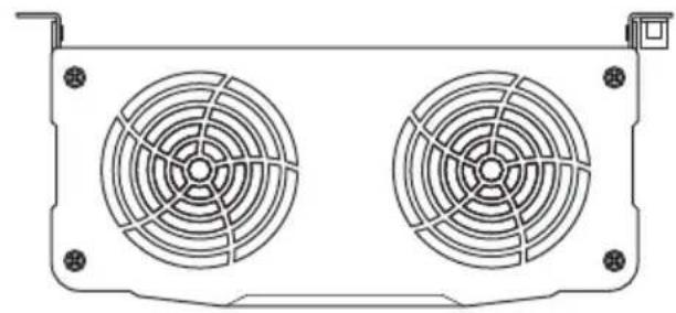
| Dimensions W x D x H: | 283 x 436 x 128.4 mmsee fig. 13, page 8 | 496 x 283 x 128.4 mmsee fig. 13, page 8 | ||
| Weight: | 7.5 kg | 9 kg | ||
Overvoltage shutdown
| Device | Overvoltage warning | Overvoltage | |
| Shutdown Restart | |||
| MSI2312T, MSI3512T 15.5 V | 16 V 15 V | ||
| MSI2324T, MSI3524T 31 V 3 | 2 V 30 V | ||
Undervoltage shutdown
| Device | Undervoltage warning | Undervoltage | |
| Shutdown Restart | |||
| MSI2312T, MSI3512T 10.5 V | 10 V 12 V | ||
| MSI2324T, MSI3524T 21.5 V | 20 V 25 V | ||
Approvals
The device has E13 certification.

In compliance with the EMC directive 2004/108/EC including 2009/19/EC and the Low-voltage Directive 2006/95/EC
IEC61558-1
IEC61558-2-16
EN55014-1
EN55014-2
EN61000-3-2
EN61000-3-3
Output power is dependent on ambient temperature and input voltage
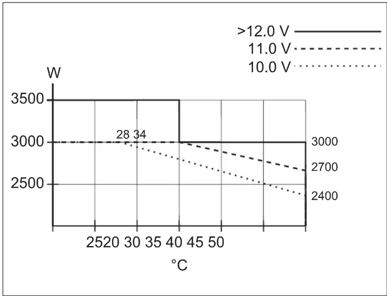
line
| °C | >12.0 V | 11.0 V | 10.0 V | |------|---------|--------|--------| | 28 | 3000 | 3000 | 3000 | | 34 | 3000 | 3000 | 3000 | | 40 | 3000 | 3000 | 2800 | | 50 | 3000 | 2700 | 2500 | | 60 | 3000 | 2600 | 2400 |7 Description technique
Control remoto MCR-7
Control remoto MCR-9
Controllo remoto MCR-7
Controllo remoto MCR-9
Fastsett innstillinger
Controlo remoto MCR-7
Controlo remoto MCR-9
Dometic Australia Pty. Ltd.
1 John Duncan Court
Varsity Lakes QLD 4227
+61 7 55076000
+61 7 55076001
Mail: sales@dometic-waeco.com.au
AUSTRIA
Dometic Austria GmbH
The Gateway · 25 Canton Road,
Tsim Sha Tsui · Kowloon
Hong Kong
+852 24611386
吕 +852 24665553
Mail: info@dometic-waeco.com.hk
ITALY
Dometic Italy S.r.l.
Via Virgilio, 3
I-47100 Forll
+39 0543 754901
+39 0543 756631
Mail: info@dometic.it
NORWAY
Dometic Norway AS
Skolmar 24
N-3232 Sandefjord
+47 33428450
+47 33428459
Mail: firmapost@waeco.no
POLAND
Dometic Poland Sp. z o.o.
Ul. Puławska 435A
02-801 Warszawa
Poland
+48 22 414 32 00
+48 22 414 32 01
Mail: info@dometic.pl
RUSSIA
Dometic RUS LLC
Komsomolskaya square 6-1
107140 Moscow
Russia
+7 495 780 79 39
+7 495 916 56 53
Mail: info@dometic.ru
SLOVAKIA
Dometic Slovakia s.r.o.
Tehelná 8
SK-98601 Fil'akovo
+421 47 4319 107
+421 47 4319 166
Mail: info@dometic.sk
SPAIN
Dometic Spain S.L.
Avda. Sierra del Guadarrama, 16
E-28691 Villanueva de la Cañada
Madrid
+34 902 111 042
+34 900 100 245
Mail: info@dometic.es
SWEDEN
Dometic Scandinavia AB
Gustaf Melins gata 7
Dometic Switzerland AG
Riedackerstrasse 7a
CH-8153 Rümlang (Zürich)
+41 44 8187171
吕 +41 44 8187191
Mail: info@dometic-waeco.ch
TAIWAN
WAECO Impex Ltd.
Taipei Office
2 FL-3 · No. 56 Tunhua South Rd, Sec 2
Taipei 106, Taiwan
+886 2 27014090
+886 2 27060119
Mail: marketing@dometic-waeco.com.tw
UNITED KINGDOM
Dometic UK Ltd.
Dometic House · The Brewery
Blandford St. Mary
Dorset DT11 9LS
+44 844 626 0133
吕 +44 844 626 0143
Mail: sales@dometic.co.uk
UNITED ARAB STATES
Dometic Middle East FZCO
P. O. Box 17860
S-D 6, Jebel Ali Freezone
Dubai, United Arab Emirates
+971 4 883 3858
昌 +971 4 883 3868
Mail: info@dometic.ae
UNITED STATES OF AMERICA
Dometic Marine Division
2000 N. Andrews Ave. Extension
Pompano Beach, FL 33069 USA
+1 954 973 2477
+1 954 979 4414
Mail: marinesales@dometicusa.com