
STF8 - Flash OLYMPUS - Free user manual and instructions
Find the device manual for free STF8 OLYMPUS in PDF.
| Product Type | Macro external electronic flash for digital camera |
| Brand | Olympus |
| Model | STF-8 |
| Dimensions (controller) | 66.9 × 59.1 × 68.5 mm |
| Dimensions (light emitting part) | 45.4 × 39.7 × 42.3 mm (per unit) |
| Weight | Approx. 283 g (without batteries, seals, or lens rings) |
| Power supply | 4 AA batteries (NiMH or alkaline) |
| Guide number (1 flash) | 6.0 (ISO 100), 8.5 (ISO 200) |
| Guide number (2 flashes) | 8.5 (ISO 100), 12.0 (ISO 200) |
| Illumination angle | Up-down 60°, left-right 72° (per flash) |
| Bounce angle | Up-down 100° (per flash) |
| Flash modes | TTL-AUTO, MANUAL |
| Number of flashes (full power) | Approx. 1,330 (NiMH) / 480 (alkaline) |
| Recycle time | Approx. 4 seconds (NiMH or alkaline) |
| Splash resistance | IPX1 (equivalent to JISC0920/IEC60529) |
| Operating temperature | -10 to 40 °C |
| Operating humidity | 30 to 90% |
| Wireless control | Compatible with RC mode (compatible Olympus cameras) |
| Included accessories | 2 lens rings (46 and 62 mm), 2 diffusers with strap, instruction manual, warranty card |
| Maintenance and cleaning | Wipe with a dry cloth. Avoid moisture and shocks. |
| Safety | Do not use near flammable gases. Do not disassemble. Keep out of reach of children. |
| Spare parts and repairability | Contact the dealer or an authorized Olympus service center for repairs. |
Frequently Asked Questions - STF8 OLYMPUS
User questions about STF8 OLYMPUS
0 question about this device. Answer the ones you know or ask your own.
Ask a new question about this device
Download the instructions for your Flash in PDF format for free! Find your manual STF8 - OLYMPUS and take your electronic device back in hand. On this page are published all the documents necessary for the use of your device. STF8 by OLYMPUS.
USER MANUAL STF8 OLYMPUS
IMPORTANT SAFETY INSTRUCTIONS
When using your photographic equipment, basic safety precautions should always be followed, including the following:
- Read and understand all instructions before using.
- Close supervision is necessary when any fl ash is used by or near children. Do not leave fl ash unattended while in use.
- Care must be taken as burns can occur from touching hot parts.
- Do not operate if the fl ash has been dropped or damaged - until it has been examined by qualified service personnel.
- Let fl ash cool completely before putting away.
- To reduce the risk of electric shock, do not immerse this flash in water or other liquids.
- To reduce the risk of electric shock, do not disassemble this flash, but take it to qualified service personnel when service or repair work is required. Incorrect reassembly can cause electric shock when the flash is used subsequently.
- The use of an accessory attachment not recommended by the manufacturer may cause a risk of fire, electric shock, or injury to persons.
SAVE THESE INSTRUCTIONS
natural_image
Line drawing of a closed container or food item (no text or symbols)- フラッシュケース
natural_image
Simple line drawing of a ring or washer (no text or symbols)natural_image
Technical line drawing of a mechanical housing component (no text or symbols)- ジョイ ント2(個)
natural_image
Simple line drawing of a rectangular device with a grid pattern and a handle (no text or symbols)
natural_image
Technical line drawing of a mechanical device with three cylindrical components and labeled terminals (no text or symbols present)natural_image
Mechanical assembly diagram showing a bearing and gear assembly with a magnified inset highlighting rotational components (no text or labels)natural_image
Diagram of a camera with a rotating wheel and gear assembly (no text or symbols)natural_image
Technical line drawing of a camera module with attached electrical connector (no text or symbols)すべての取り付けが完了した状態です。

natural_image
Line drawing of a mechanical device with coiled hoses and housing (no text or symbols)2 発光部の角度を調節する
natural_image
Diagram of a mechanical device with a magnified inset showing a textured surface detail (no text or symbols)発光部を三脚に設置する
natural_image
Line drawing of a tripod-mounted device with a central hub and three legs (no text or symbols)Thank you for purchasing this Olympus product. To ensure your safety, please read this instruction manual before use, and keep it handy for future reference.
Checking the package contents
Check that all of the parts and accessories shown below are included in the package. If any item is missing or damaged, contact your dealer.

natural_image
Line drawing of two connected electrical devices with coiled cables (no text or symbols)- Macro flash main unit
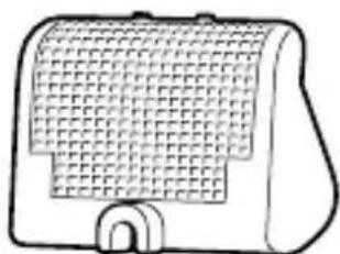
natural_image
Line drawing of a closed container or food item (no text or symbols)- Flash case

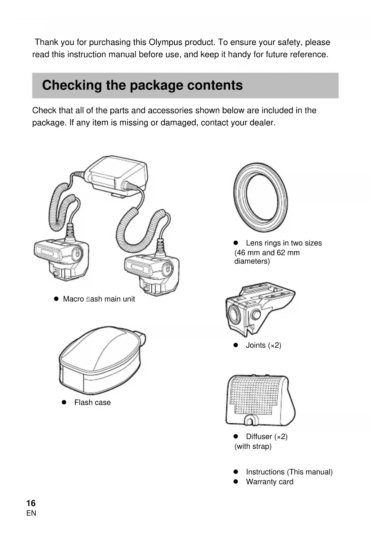
natural_image
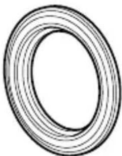
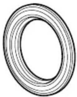
Simple line drawing of a ring or washer (no text or symbols)● Lens rings in two sizes (46 mm and 62 mm diameters)

natural_image
Technical line drawing of a mechanical housing component (no text or symbols)- Joints (×2)

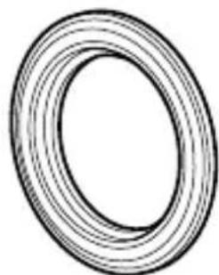
natural_image
Simple line drawing of a rectangular device with a grid pattern and a curved base (no text or symbols)● Diffuser (×2) (with strap)
- Instructions (This manual)
- Warranty card
Names of Parts
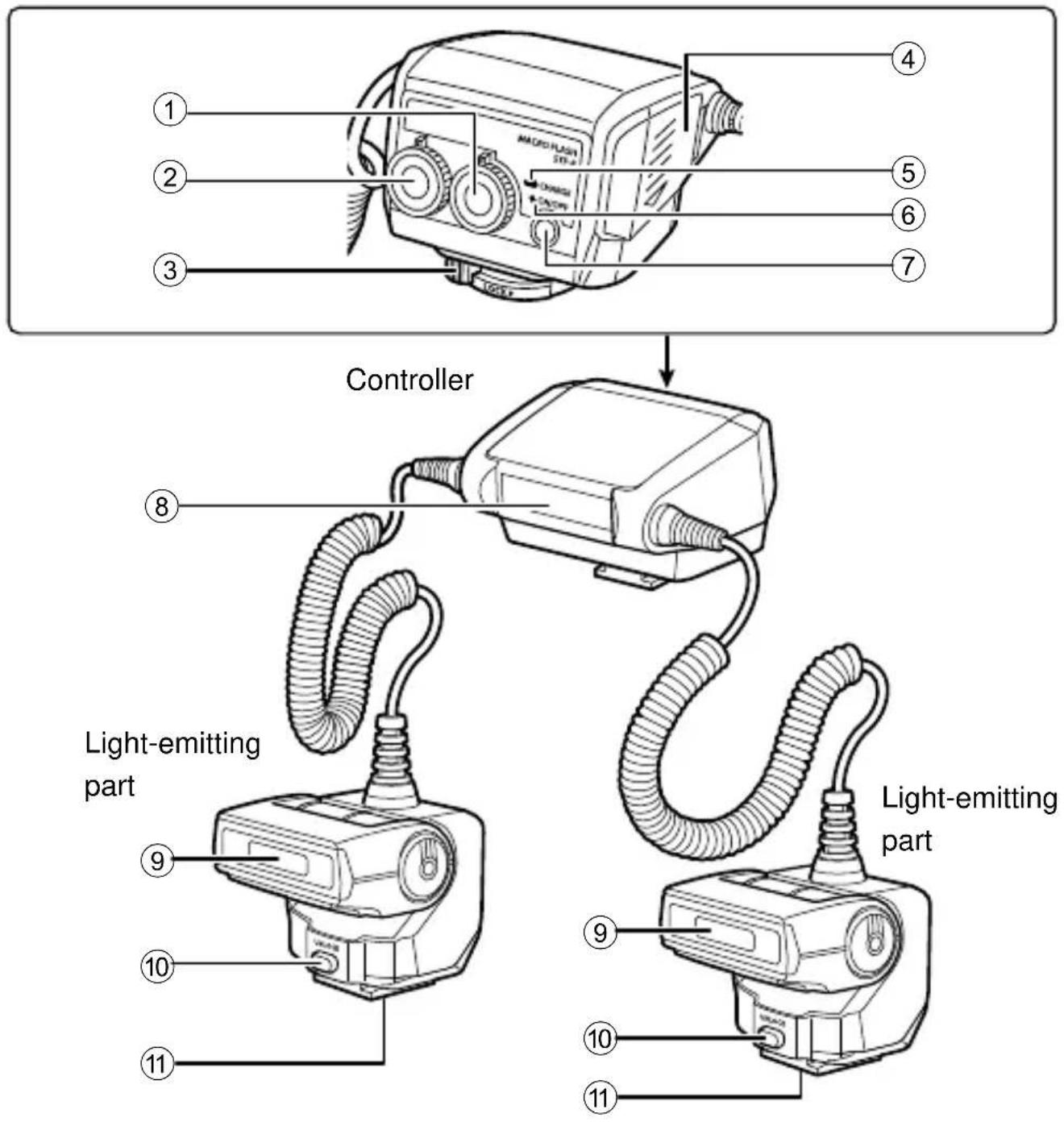
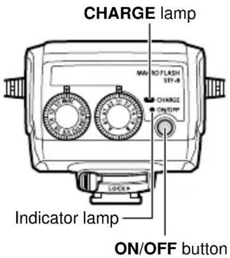
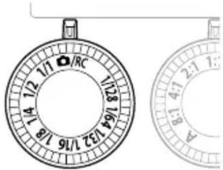
① Flash ratio dial
② Mode dial
③ Latch
④ Battery compartment cover
⑤ CHARGE lamp
⑥ Indicator lamp
⑦ ON/OFF button
⑧ Remote light-emitting window
⑨ Light-emitting window
⑩ UNLOCK button
⑪ Tripod socket
Preparing for Shooting
Preparing a Battery (Solo
Choose from the below batteries:
- AA (R6) NiMH batteries ( × 4) • AA (R6) alkaline batteries ( × 4)
AA (R6) manganese batteries cannot be used.
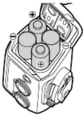
Loading Batteries
1 Open the battery compartment cover.
2 Insert the batteries with correct +/- polarity.
3 Close the battery compartment cover.

natural_image
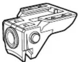
Diagram of a mechanical device with three cylindrical components and labeled terminals (no text or symbols present)Attaching to the Camera
Confirm that both the camera and the macro flash are off. Attaching or removing the macro flash while either the flash or the camera is on may result in malfunction.
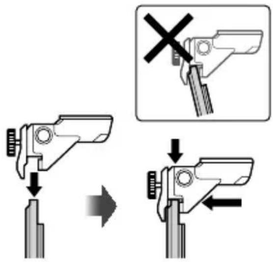
1 If the screws on the joints are tightened, loosen them (①).
2 While holding down the buttons on both sides of the joint (②), attach the joint to the lens ring (③).
- Choose the lens ring whose size matches the filter diameter of the lens to be used.

- While holding down the buttons on both sides of the joint, insert the lens ring perpendicularly all the way into the joint so that the teeth of the joint press against it as shown in the figure. Keep the lens ring straight when inserting it.
3 Tighten the screws to secure the joint to the lens ring.
- If you want to change the position of the joint on the lens ring, move it along the lens ring while holding down the buttons on both sides of the joint.
- When detaching the joint, loosen the screw and remove the joint from the lens ring. Keep the joint straight while turning the screw.
- Repeat steps 1-3 to attach the other joint.
natural_image
Technical illustration of a mechanical bearing assembly with a magnified inset showing rotational components (no text or symbols)4 Attach the lens ring fitted with the joints to the lens of the camera.
- If the joints are blocked by a camera grip or other obstacle, move the joints while attaching the lens ring.
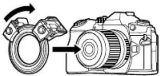
natural_image
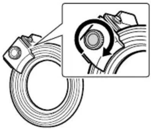
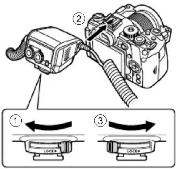
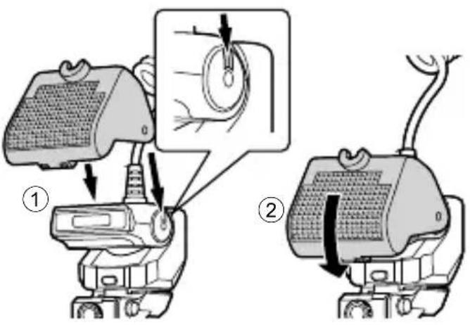
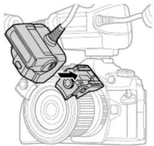
Diagram of a DSLR camera with a rotating wheel and directional arrow indicating rotation (no text or symbols)5 Slide the latch on the controller in the direction opposite to that indicated by the [LOCK ▶] icon (①).
6 Attach the controller to the camera's hot shoe (②).
- Insert it firmly all the way into the hot shoe until it clicks into place.
7 Slide the latch to the [LOCK ▶] position (③).
8 Install each light-emitting part in its respective joint.
- Insert it firmly all the way into the joint until it clicks into place.
- When removing the light-emitting part, pull it out while pressing the UNLOCK button.

natural_image
Technical line drawing of a DSLR camera with attached mechanical components (no text or symbols)This completes the installation.

natural_image
Line drawing of a mechanical device with two hoses and a central housing (no text or symbols)1 Adjust the positions of the light-emitting parts by moving them along the lens ring while holding down the buttons on the sides of the joints.
- Release the buttons to fix the position.
- It is possible to move 360^ around the lens ring.

2 Adjust the angle of the light-emitting part.
- The light-emitting part can be adjusted up and down to the angles shown in the figure.
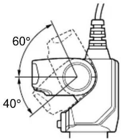
- The illumination may be insufficient when taking very close-up photos with a wide-angle lens or macro lens. In this case, use the diffuser.
"Using the diffuser" (P. 25)
Basic Shooting and Settings
Turning on the Macro Flash
Attach the macro flash to the camera, and then turn the camera and the macro flash on.
1 Press the ON/OFF button.
• The indicator lamp illuminates green.
- When the camera is powered on, the macro fl ash is automatically powered on too. The macro fl ash will also enter sleep mode whenever the camera enters sleep mode.
- When charging is complete, the CHARGE lamp lights. Charge or replace the batteries if the CHARGE lamp does not light after: 45 seconds (NiMH batteries) 45 seconds (Alkaline batteries)
Shooting
1 Set the mode dial on the macro flash to 📷/RC.
2 Use the camera controls to choose the flash mode.
- You can set it to auto or manual flash. See the camera manual for details.
3 Set the light intensity ratio.
"Setting the Light Intensity Ratio" (P. 23)
4 Press the shutter button to take the picture.

You can change the light intensity ratio of the two lights. This makes it possible to create a three-dimensional effect by applying various degrees of shading to the subject. It is also possible to use only one light.
1 Rotate the flash ratio dial to set the light intensity ratio.
- Choose a light intensity ratio of 8:1, 4:1, 2:1, 1:1, 1:2, 1:4, or 1:8.
- To use a single light, set the flash ratio dial to A or B.


You can set the flash output manually using either the flash mode of the camera or the mode dial on the macro flash. Using the camera flash mode allows finer control over the amount of light.
Setting the flash output using the flash mode of the camera
1 Set the mode dial on the macro flash to 📷/RC.
2 Use the camera controls to choose the fl ash mode manually.
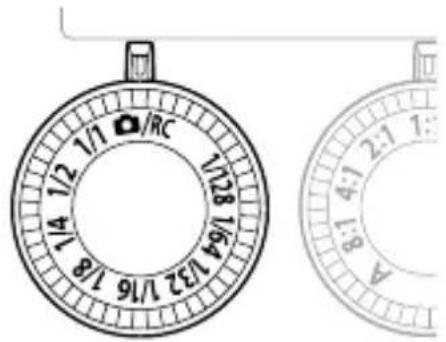
1 Set the mode dial on the macro flash to a setting from 1/1 to 1/128.
- If the settings on the macro flash and the camera are different, the macro flash setting takes precedence.
- If you are using a camera that is not from Olympus, set the flash output using the mode dial on the macro flash. “Shooting with a Non-Olympus Camera” (P. 26)
Other Features
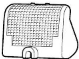
Using the diffuser
The diffuser enables shooting under soft lighting by attenuating the shades on the subject. It expands your shooting options, for example by allowing a wider aperture (F). The illumination may be insufficient when taking very close-up photos with a wide-angle lens or macro lens. The results may be improved by using the diffuser.
1 Attach the supplied diffuser to the light-emitting part (①).
- Attach the diffuser to the fl ash cable with the strap beforehand.
- Fit the notch inside the diffuser into the groove on the side of the light-emitting part.
2 To secure the diffuser, rotate it until it clicks into place in the joint (②).
- When not using the diffuser, you can keep it mounted on the light-emitting part. Just lift up the diffuser and secure it to the cable.

natural_image
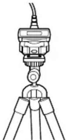
Diagram of a mechanical device with a magnified inset showing a textured surface detail (no text or symbols)Installing the Light-Emitting Part on a Tripod
The light-emitting part is equipped with a tripod hole on the bottom. You can set up the light-emitting parts by mounting them separately on their respective tripods on the left and right.
natural_image
Line drawing of a tripod-mounted surveying instrument with no visible text or symbolsThis product can connect to Olympus digital cameras that support RC mode for wireless control of multiple remote flash units. For information on cameras that support the RC mode, see the camera manual.
1 Attach the macro flash to the camera and set the mode dial to 📷/RC.
- RC mode can be used even when the mode dial setting is not 📄/RC, but the settings on the macro fl ash take precedence when determining the fl ash behavior.
2 Set the RC mode-compatible flash you want to control to RC mode and set it up.
• See the flash manual for details.
3 Set the camera to RC mode, and configure the flash control mode and other settings.
- See the camera manual for details. - This product does not support Super FP flash.
Shooting with a Non-O
If it is not possible to communicate with the camera to control the flash, set the flash output manually.
1 Set the flash output by setting the mode dial on the macro flash to between 1/1 and 1/128.
2 Press the shutter button to take the picture.

Safety precautions
Read WARNINGS and CAUTIONS thoroughly to ensure safe usage. These safety precautions protect the users and others and prevent property damage.

WARNING
Failure to observe the precautions indicated by this symbol may result in injury or death.
- Do not use flash in places where it may be exposed to flammable or explosive gas. Otherwise, fire ignition or explosion may result.
- Do not directly solder the product or modify, remodel, or disassemble.
- Do not cover the light emitting area of the flash with your hand, and do not touch the light emitting area after continuous fi ring. It may burn your skin.
- Water and foreign matter inside of the device may cause fire or electric shock. If the device is immersed in or exposed to water or foreign matter is found inside of the device, turn off the power immediately and remove batteries with care. Contact your dealer or consult an Olympus Authorized Service Station.
- To prevent a traffic accident, do not direct the flash at a person operating a motor vehicle.
- Do not use the flash or AF illuminator in close proximity to others (especially infants). Keep the flash out of reach of children. Light from the flash can cause visual impairment.
- Do not use batteries that are not specified for use.
- Do not mix old and new batteries, or batteries made by different manufacturers.
- Do not connect substances such as metal to the (+) or (−) of batteries.

CAUTION
Failure to observe the precautions indicated by this symbol may result in injury or property damage.
- If you notice any abnormalities such as odor, noise, or smoke, stop using this device. Otherwise a fire or burn may result. Remove the batteries carefully to avoid burning yourself, and contact your dealer or consult an Olympus Authorized Service Station.
- Do not operate with wet hands. This may cause malfunction or electric shock.
- Do not use or leave the batteries in a place subject to high temperatures (such as in direct sunlight, in a hot vehicle, or near the stove).
- Before attaching the macro flash to the camera, wipe the point of contact free of dirt and moisture to prevent malfunction.
Specifications
| MODEL NO. STF-8 | |
| Product type External electronic fl ash for digital still camera | |
| Guide number When using 1 fl ash: 6.0 (ISO100), 8.5 (ISO200)When using 2 fl ashes: 8.5 (ISO100), 12.0 (ISO200) | |
| Firing angle Up-down 60°, left-right 72° (1 fl ash) | |
| Bounce angle Up-down 100° (1 fl ash) | |
| Flash modes TTL-AUTO, MANUAL | |
| Flash emission count(at full activation)* | Approx. 1,330 times (using AA (R6) NiMH batteries)Approx. 480 times (using AA (R6) alkaline batteries) |
| Recharge time Approx. 4 seconds (using AA (R6) NiMH batteries)Approx. 4 seconds (using AA (R6) alkaline batteries)(from full activation to CHARGE lamp lighting)* | |
| Splash resistance Class 1 protection (IPX1): JISC0920/IEC60529 equivalent(measurements obtained from in-house tests at Olympus) | |
| Operating environment | Temperature: -10 to 40°C (14 to 104°F)Humidity: 30 to 90% |
| Dimensions Controller | 66.9 (W) × 59.1 (H) × 68.5 (D) mm(2.6 × 2.3 × 2.7 in.)Light-emitting part (1 fl ash): 45.4 (W) × 39.7 (H) × 42.3 (D) mm(1.8 × 1.6 × 1.7 in.) |
| Weight Approx. 283 g (10 oz.) (excluding batteries, joints and lens rings) | |
* Measurements obtained from in-house tests at Olympus. Actual figures may vary depending on shooting conditions.
Specifications are subject to change without any notice or obligation on the part of the manufacturer.
For customers in North America, Central America, South America and the Caribbean FCC Notice
This device complies with part 15 of the FCC rules. Operation is subject to the following two conditions:
(1) This device may not cause harmful interference, and (2) this device must accept any interference received, including interference that may cause undesired operation. Any unauthorized changes or modifications to this equipment would void the user's authority to operate.
CAN ICES-3(B)/NMB-3(B)
For customers in Europe

This symbol [crossed-out wheeled bin WEEE Annex IV] indicates separate collection of waste electrical and electronic equipment in the EU countries.
Please do not throw the equipment into the domestic refuse.
Please use the return and collection systems available in your country for the disposal of this product.
Technical Support (U.S.A. / Canada)
24/7 online automated help : http://www.olympusamerica.com/support
Phone customer support : Tel.1-800-260-1625 (Toll-free)
Our phone customer support is available from 9 am to 9 pm (Monday to Friday) ET
E-Mail : distec@olympus.com
European Technical Customer Support
Please visit our homepage http://www.olympus-europa.com
or call: Tel. 00800 - 67 10 83 00 (Toll-free) +49 40 - 237 73 899 (Charged)
natural_image
Line drawing of two connected electrical connectors with coiled cables (no text or symbols)natural_image
Line drawing of a closed container or food item (no text or symbols)- Étui de fl ash
natural_image
Simple line drawing of a ring or washer (no text or symbols)natural_image
Technical line drawing of a mechanical housing component (no text or symbols)- Joints (× 2)

natural_image
Simple line drawing of a rectangular device with a grid pattern and an open door (no text or symbols)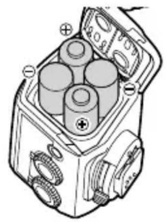
natural_image
Technical diagram of a mechanical device with cylindrical components and labeled terminals (no readable text or symbols)natural_image
Technical illustration of a mechanical component with a magnified inset showing rotational assembly (no text or symbols)natural_image
Diagram of a DSLR camera showing wheel and gear assembly (no text or symbols)

natural_image
Technical line drawing of a camera module with attached electrical connector (no text or symbols)natural_image
Line drawing of a mechanical device with coiled hoses and central hub (no text or symbols)
natural_image
Mechanical device with attached cable and mesh component, shown with magnified detail (no text or symbols)natural_image
Line drawing of a tripod-mounted device with a central knob and three legs (no text or symbols)natural_image
Line drawing of two connected electrical connectors with coiled wires (no text or symbols)natural_image
Line drawing of a closed container or container with lid and side handle (no text or symbols)- Carcasa del flash

natural_image
Simple line drawing of a ring or washer (no text or symbols)natural_image
Technical line drawing of a mechanical component with cylindrical and rectangular features (no text or symbols)- Juntas (×2)

natural_image
Simple line drawing of a rectangular device with grid pattern and a handle (no text or symbols)natural_image
Technical illustration of a mechanical component with a magnified inset showing rotational motion (no text or symbols)natural_image
Diagram of a camera with a rotating wheel and external gear assembly (no text or symbols)
natural_image
Technical line drawing of a camera assembly with mechanical components (no text or symbols)natural_image
Line drawing of a mechanical device with coiled hoses and central housing (no text or symbols)
natural_image
Diagram of a mechanical device with a magnified inset showing a textured surface detail (no text or symbols)natural_image
Line drawing of a tripod-mounted surveying instrument with no visible text or symbolsnatural_image
Line drawing of two connected electrical devices with coiled cables (no text or symbols)● 매크로플래시 메인 장치

natural_image
Line drawing of a closed container or food bag (no text or symbols)- 플래시케이스
natural_image
Simple line drawing of a ring or washer (no text or symbols)natural_image
Technical line drawing of a mechanical housing component (no text or symbols)-연결부(×2)

natural_image
Simple line drawing of a rectangular device with a grid pattern and a U-shaped base (no text or symbols)
natural_image
Technical diagram of a mechanical device with cylindrical components and gear-like components (no text or symbols)부착카메라
natural_image
Technical illustration of a mechanical component with a magnified inset showing rotational assembly (no text or symbols)natural_image
Diagram of a camera with a rotating wheel and gear mechanism, showing motion direction (no text or symbols)natural_image
Technical line drawing of a camera assembly with a mechanical component inserted (no text or symbols)설치가 완료된 모습입니다.

natural_image
Line drawing of a mechanical device with coiled hoses and central hub (no text or symbols)2 발광 부분의 각도를 조정합니다.
찰영
부분을 삼각대에 설치광원
natural_image
Line drawing of a tripod-mounted surveying instrument with no visible text or symbols제조자: OLYMPUS CORPORATION
natural_image
Line drawing of two connected electrical devices with coiled cables (no text or symbols)- 微距閃光燈主機

natural_image
Simple line drawing of a ring or washer (no text or symbols)natural_image
Line drawing of a closed container with lid and side handle (no text or symbols)- 閃光燈盒
natural_image
Technical line drawing of a mechanical housing component (no text or symbols)- 轉接頭 (×2)
natural_image
Simple line drawing of a rectangular device with a grid pattern and a curved base (no text or symbols)
natural_image
Technical diagram of a mechanical device with four cylindrical components and labeled terminals (no text or symbols present)安裝到相機上
3 鎖緊螺絲將轉接頭固定在鏡頭環上。
natural_image
Mechanical assembly diagram showing a coiled spring with a magnified inset highlighting the internal mechanism (no text or symbols present)natural_image
Diagram of a camera with a rotating wheel and gear mechanism, showing motion direction (no text or symbols)natural_image
Technical line drawing of a camera assembly with mechanical components (no text or symbols)這樣便可完成安裝。

natural_image
Line drawing of a mechanical device with coiled hoses and central housing (no text or symbols)2 調整發光部件的角度。

natural_image
Diagram of a device with a magnified inset showing a textured surface detail (no text or symbols)將發光部件安裝在三腳架上
natural_image
Line drawing of a tripod-mounted surveying instrument with no visible text or symbolsnatural_image
Line drawing of two connected electrical devices with coiled cables (no text or symbols)- ขุดแพลขมาใคร

natural_image
Line drawing of a closed container or food item (no text or symbols)- ของใส่แพลข

natural_image
Simple line drawing of a ring or washer (no text or symbols)natural_image
Technical line drawing of a mechanical housing component (no text or symbols)- ข้อต่อ (×2)
natural_image
Simple line drawing of a rectangular device with a grid pattern and a U-shaped base (no text or symbols)
natural_image
Technical diagram of a mechanical device with four cylindrical components and labeled terminals (no text or symbols present)การติดเข้ากับกล้อง
natural_image
Technical illustration of a mechanical component with concentric rings and a magnified inset showing rotational motion (no text or symbols)natural_image
Diagram of a DSLR camera showing the wheel being twisted with an arrow indicating rotation (no text or symbols present)
natural_image
Technical line drawing of a camera module with attached electrical connector (no text or symbols)natural_image
Line drawing of a mechanical device with coiled hoses and housing (no text or symbols)
natural_image
Diagram of a mechanical device with a magnified inset showing a textured component (no text or symbols)natural_image
Line drawing of a tripod-mounted device with a central hub and three legs (no text or symbols)natural_image
Line drawing of two connected electrical devices with coiled cables (no text or symbols)natural_image
Line drawing of a closed container or food item (no text or symbols)- Pouzdro na blesk

natural_image
Simple line drawing of a ring or washer (no text or symbols)natural_image
Technical line drawing of a mechanical housing component (no text or symbols)• Nástavce (×2)
natural_image
Simple line drawing of a portable device with a grid-patterned cover and a handle (no text or symbols)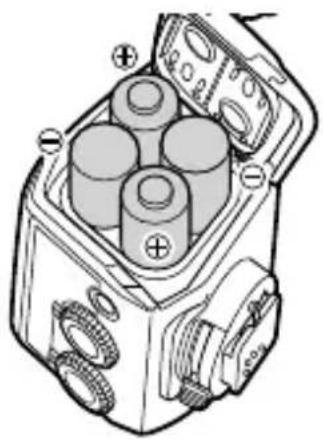
natural_image
Technical diagram of a mechanical device with cylindrical components and labeled terminals (no text or symbols present)natural_image
Technical illustration of a mechanical component with a magnified inset showing rotational motion (no text or symbols)natural_image
Diagram of a DSLR camera with a rotating wheel and external gear assembly (no text or symbols)natural_image
Technical line drawing of a camera assembly with a mechanical component inserted (no text or symbols)natural_image
Technical line drawing of a mechanical device with coiled hoses and housing (no text or symbols)natural_image
Line drawing of a tripod-mounted device with a central knob and three legs (no text or symbols)natural_image
Line drawing of two connected electrical devices with coiled cables (no text or symbols)natural_image
Line drawing of a closed container or food item (no text or symbols)- Blitztasche

natural_image
Simple line drawing of a ring or washer (no text or symbols)natural_image
Technical line drawing of a mechanical housing component (no text or symbols)- Halterungen (2x)
natural_image
Simple line drawing of a rectangular device with a grid pattern and a handle (no text or symbols)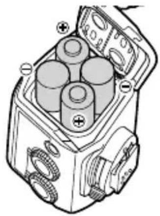
natural_image
Technical diagram of a mechanical device with three cylindrical components and labeled ports (no text or symbols present)natural_image
Technical illustration of a mechanical component with a magnified inset showing rotational motion (no text or symbols)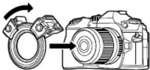
natural_image
Diagram of a DSLR camera with a rotating ring and directional arrow indicating rotation (no text or symbols)
natural_image
Technical line drawing of a camera module with attached electrical connector (no text or symbols)natural_image
Technical line drawing of a mechanical device with coiled hoses and central components (no text or symbols)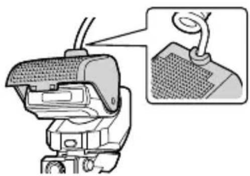
natural_image
Diagram of a mechanical device with a magnified inset showing a component detail (no text or symbols present)Montage der Blitze
natural_image
Line drawing of a tripod-mounted scientific instrument with a central knob (no text or symbols)natural_image
Line drawing of two connected electrical devices with coiled cables (no text or symbols)natural_image
Line drawing of a closed container or food box (no text or symbols)- Salaman kotelo

natural_image
Simple line drawing of a ring or washer (no text or symbols)natural_image
Technical line drawing of a mechanical housing component (no text or symbols)Kiinnitinosat (× 2)

natural_image
Simple line drawing of a rectangular device with grid pattern and a U-shaped handle (no text or symbols)natural_image
Technical illustration of a mechanical component with a magnified inset showing rotational motion (no text or symbols)natural_image
Diagram of a DSLR camera with a rotating wheel and external gear (no text or symbols)
natural_image
Technical line drawing of a camera assembly with a mechanical component inserted (no text or symbols)natural_image
Line drawing of a mechanical device with coiled hoses and housing (no text or symbols)
natural_image
Diagram of a mechanical device with a magnified inset showing a cable or spring attached to a textured surface (no text or symbols present)natural_image
Line drawing of a tripod-mounted device with a central knob and three legs (no text or symbols)natural_image
Line drawing of two connected electrical devices with coiled cables (no text or symbols)natural_image
Line drawing of a closed container or food item (no text or symbols)natural_image
Simple line drawing of a ring or washer (no text or symbols)natural_image
Technical line drawing of a mechanical housing component (no text or symbols)- Uchwyty (×2)

natural_image
Simple line drawing of a portable device with a grid-patterned cover and a handle (no text or symbols)natural_image
Technical illustration of a mechanical component with a magnified inset showing rotational motion (no text or symbols)natural_image
Diagram of a DSLR camera with a rotating ring and directional arrow indicating rotation (no text or symbols)
natural_image
Technical line drawing of a camera module with attached components (no text or symbols)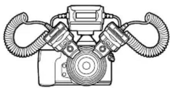
natural_image
Line drawing of a mechanical device with dual hoses and central housing (no text or symbols)
natural_image
Diagram of a mechanical device with a magnified inset showing a textured surface detail (no text or symbols)natural_image
Line drawing of a tripod-mounted scientific instrument with a central knob (no text or symbols)natural_image
Line drawing of two connected electrical devices with coiled cables (no text or symbols)natural_image
Line drawing of a closed container or food bag (no text or symbols)- Футляр для вспышки

natural_image
Simple line drawing of a ring or washer (no text or symbols)natural_image
Technical line drawing of a mechanical housing component (no text or symbols)- Кронштейны (×2)

natural_image
Simple line drawing of a rectangular device with grid pattern and a small bracket at the bottom (no text or symbols)
natural_image
Technical diagram of a mechanical device with four cylindrical components and labeled terminals (no text or symbols present)natural_image
Technical illustration of a mechanical component with a magnified inset showing rotational assembly (no text or symbols)natural_image
Diagram of a DSLR camera with a rotating wheel and directional arrow indicating rotation (no text or symbols)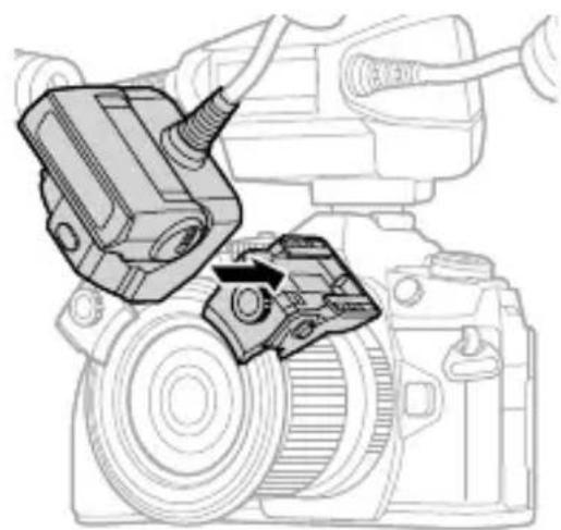
natural_image
Technical line drawing of a camera assembly with a mechanical component inserted (no text or symbols)natural_image
Line drawing of a mechanical device with coiled hoses and central components (no text or symbols)
natural_image
Diagram of a mechanical device with a magnified inset showing a textured surface detail (no text or symbols)natural_image
Line drawing of a tripod-mounted surveying instrument with no visible text or symbolsdate of issue 2016.08.
OLYMPUS®

- IMPORTANT SAFETY INSTRUCTIONS
- SAVE THESE INSTRUCTIONS
- 発光部を三脚に設置する
- Checking the package contents
- Names of Parts
- Preparing for Shooting
- Preparing a Battery (Solo
- Loading Batteries
- Attaching to the Camera
- Tighten the screws to secure the joint to the lens ring.
- Attach the lens ring fitted with the joints to the lens of the camera.
- Basic Shooting and Settings
- Turning on the Macro Flash
- Press the ON/OFF button.
- Shooting
- Rotate the flash ratio dial to set the light intensity ratio.
- Setting the flash output using the flash mode of the camera
- Other Features
- Using the diffuser
- Installing the Light-Emitting Part on a Tripod
- Shooting with a Non-O
- Safety precautions
- WARNING
- CAUTION
- Specifications
- For customers in North America, Central America, South America and the Caribbean FCC Notice
- For customers in Europe
- Technical Support (U.S.A. / Canada)
- European Technical Customer Support
- 부착카메라
- 찰영
- 부분을 삼각대에 설치광원
- 安裝到相機上
- 將發光部件安裝在三腳架上
- การติดเข้ากับกล้อง
- Montage der Blitze
- OLYMPUS®
Brand : OLYMPUS
Model : STF8
Category : Flash