
FL‑900R - Flash OLYMPUS - Free user manual and instructions
Find the device manual for free FL‑900R OLYMPUS in PDF.


| Product Type | Cobra electronic flash for Olympus cameras |
| Brand | Olympus |
| Model | FL-900R |
| Dimensions (W x H x D) | Approx. 78 x 108 x 107 mm |
| Weight (without batteries) | Approx. 318 g |
| Power Source | 4 AA (LR6) batteries or Ni-MH rechargeable batteries |
| Number of Batteries | 4 |
| Guide Number (GN) at ISO 100 | 50 m (at 85 mm zoom) |
| Coverage Angle (Zoom) | 24 – 85 mm (20 mm with diffuser) |
| Recycling Time | Approx. 0.2 – 5.0 s (fresh alkaline batteries) |
| Number of Flashes (Approx.) | 280 flashes (fresh alkaline batteries) |
| Flash Modes | TTL Auto, Manual, Multi (stroboscopic), Wireless |
| Synchronization | 1st curtain, 2nd curtain, High-speed (FP up to 1/8000 s) |
| Exposure Compensation | ±3 EV in 0.3 EV increments |
| Wireless Control | Yes (RC, multiple groups) |
| Tilt/Swivel Head | Vertical: 7 positions (0° to 90°); Horizontal: 270° (left/right) |
| Display | Backlit LCD screen |
| Firmware Update | Via camera body or USB cable (with Olympus software) |
| Maintenance and Cleaning | Wipe with a soft, dry cloth; avoid solvents |
| Safety | Do not expose to water, shocks, or extreme temperatures |
| Spare Parts and Repairability | Contact an authorized Olympus service center; batteries and diffuser are replaceable |
| General Information | Flash compatible with Olympus and Panasonic Micro 4/3 cameras |
Frequently Asked Questions - FL‑900R OLYMPUS
User questions about FL‑900R OLYMPUS
0 question about this device. Answer the ones you know or ask your own.
Ask a new question about this device
Download the instructions for your Flash in PDF format for free! Find your manual FL‑900R - OLYMPUS and take your electronic device back in hand. On this page are published all the documents necessary for the use of your device. FL‑900R by OLYMPUS.
USER MANUAL FL‑900R OLYMPUS
IMPORTANT SAFETY INSTRUCTIONS
When using your photographic equipment, basic safety precautions should always be followed, including the following:
- Read and understand all instructions before using.
- Close supervision is necessary when any flash is used by or near children. Do not leave flash unattended while in use.
- Care must be taken as burns can occur from touching hot parts.
- Do not operate if the flash has been dropped or damaged - until it has been examined by qualified service personnel.
- Let flash cool completely before putting away.
- To reduce the risk of electric shock, do not immerse this flash in water or other liquids.
- To reduce the risk of electric shock, do not disassemble this flash, but take it to qualified service personnel when service or repair work is required. Incorrect reassembly can cause electric shock when the flash is used subsequently.
- The use of an accessory attachment not recommended by the manufacturer may cause a risk of fire, electric shock, or injury to persons.
SAVE THESE INSTRUCTIONS
The following importer description applies to products imported into the EU directly by OLYMPUS EUROPA SE & Co. KG only.
OLYMPUS EUROPA SE & Co. KG
Wendenstrasse 14-18, 20097 Hamburg, Germany
natural_image
Diagram of a mechanical device with directional arrows indicating rotation or movement (no text or symbols)2 電池の向きを正しく合わせて入れる

natural_image
Diagram of a mechanical device with three cylindrical components and polarity indicators (no text or symbols)3 電池カバーを閉じる
カメラに取り付ける
natural_image
Diagram of a handheld electronic device with a cable inserted, labeled with number 2 (no text or symbols on the device itself)- 設定画面が表示されます。

3 ダイヤルを回して設定を変更する
natural_image
Diagram of a cylindrical device with a downward arrow indicating a component (no text or symbols present)natural_image
Simple line drawing of a printer with an upward arrow indicating compression (no text or symbols)バウンスアダプターを使う
natural_image
Simple line drawing of a computer monitor with an arrow indicating rotation (no text or symbols)IR フィルターを使う
natural_image
Simple line drawing of a mechanical component with no text or symbolsメニューの設定
設定できる機能
は初期設定を表しています。
スレーブ
安全上のご注意
Thank you for purchasing this Olympus product. To ensure your safety, please read this instruction manual before use, and keep it handy for future reference.
Names of Parts

① Wide panel P. 32
② Light-emitting area
③ Remote sensor
④ AF illuminator/LED window
⑤ Auto light receptor
⑥ Catch light plate P. 32
⑦ Control panel ...... P. 23
⑧ MODE button P. 26
⑨ TEST button/CHARGE lamp
⑩ OK button
⑪ Bounce lock release button ..... P. 32
⑫ AUTO CHECK lamp
⑬ ON/OFF button P. 25
⑭ Latch release ...... P. 24, 30
⑮ Latch P. 24, 30
⑯ Dial
a: ZOOM button (△) ...... P. 28
b: fl ash compensation button (◀)
P
c: LED light button (▷) ..... P. 28
d: MENU/🔒 button (▽) ...... P. 28, 34
⑰ Flash stand FLST-1 P. 30
⑱ Bounce adapter ...... P. 33
⑲ IR filter P. 33
⑳ Flash case

TTL-AUTO and AUTO modes

MULTI mode

line
| Position | Value | |---|---| | Gno | 5.9 | | Hz | 10 | | TIME | 5 | ⑬ | 13 | ⑮ | 15 | ⑯ | 16 | ⑰ | | ⑱ | | ⑲ | | ⑳ | | ⑺ | | ⑻ | | ⑼ | |M mode

RC mode
① Super FP flash
② Flash control mode ...... P. 26
③ Flash intensity control..... P. 28
④ FOUR THIRDS
⑤ Zoom mode P. 28
⑥ Zoom position
(angle of illumination).... P. 28
⑦ LED light mode P. 34
⑧ LED light P. 28
⑨ Temperature warning
⑩ Control lock.... P. 28
⑪ Slave.... P. 36
⑫ Range P. 25
⑬ Guide number (GN) P. 36
⑭ Optimal shooting distance ..... P. 26
⑮ Frequency.... P. 26
⑯ Number of flashes ...... P. 26
⑰ RC mode group ...... P. 30
⑱ RC mode channel.... P. 30
Readying the Flash
Preparing a Battery (Sold S
Choose from the below batteries:
AA (R6) NiMH batteries ( × 4)
AA (R6) alkaline batteries ( × 4)
• AA (R6) manganese batteries cannot be used.
Loading Batteries
1 Open the battery compartment cover.
2 Insert the batteries with correct +/- polarity.
3 Close the battery compartment cover.

natural_image
Mechanical component diagram showing a cylindrical housing with internal components and directional arrows (no text or symbols)
natural_image
Mechanical assembly diagram showing a piston and cylinder components (no text or labels)Attaching to the Camera
Confirm that both the camera and electronic flash are off. Attaching or removing the electronic flash while either the flash or the camera is on may result in malfunction.
- Dirt or water on the contacts can cause malfunction. Remove dirt, water, and other foreign matter before attaching the unit to the camera.
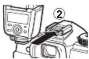
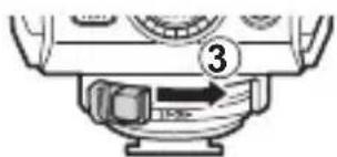
1 Keeping the latch release pressed, slide the latch in the direction opposite to that shown by the [LOCK▶] arrow to undo the latch (①).
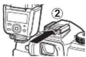
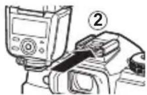
2 Slide the flash into the hot shoe until it clicks securely into place (②).
3 Slide the latch to the [LOCK▶] position (③).
• To remove the flash, undo the latch as described in Step 1 and slide the unit from the camera.

natural_image
Illustration of a device being inserted into a cable, showing a screen and cable connector (no text or symbols)
Attach an electronic flash to the camera, and then turn the camera on.
1 Press the ON/OFF button.
• The control panel display will turn on.
- To turn the flash off, press the ON/OFF button again.
- Replace the batteries if the CHARGE lamp does not light after:
10 seconds (NiMH batteries) 30 seconds (Alkaline batteries)
- Turn power off before replacing the batteries. Replacing the batteries when the power is turned on could cause the flash to malfunction.
- If the CHARGE lamp and AUTO CHECK lamp blink simultaneously, batteries are running low. Replace the batteries.

- The flash will enter sleep mode whenever the camera enters sleep mode.
- If no operations are performed for approximately 60 minutes, the flash will turn off automatically. Press the ON/OFF button to turn it on.
Basic Photography and Settings
Shooting
1 Use camera controls to choose the flash mode.
• See the camera manual for details.
2 Choose a flash control mode (P. 26).
3 Press the shutter button halfway.
- The camera and flash will exchange shooting information and the flash range will be displayed in the control panel.
- Flash range varies with camera settings (ISO sensitivity, aperture, and lens focal length).
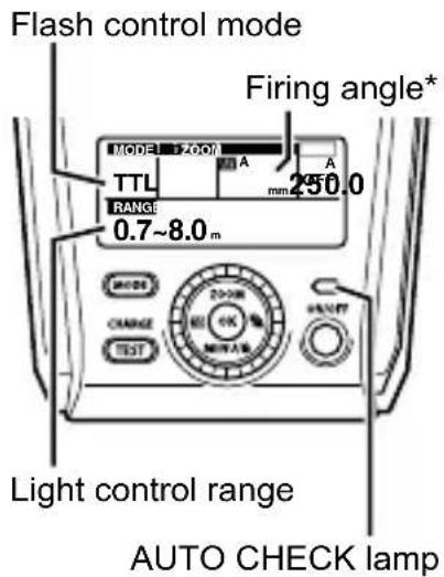
* Displayed according to the focal length of the lens.
4 Press the shutter button the rest of the way down to take the picture.
- The AUTO CHECK lamp blinks for about 5 s after shooting to indicate that the flash has fired successfully.
- When using a flash, flash light may be blocked by the lens body, lens hood, etc.
- The flash may become hot when fired many times in succession, resulting in damage or malfunction. The flash should be fired no more than 50 times in succession at intervals of 2.5 seconds, after which it should be left unused for at least 10 minutes.
Test Flash
To fire a test flash, press the TEST button while the CHARGE lamp is lit. The AUTO CHECK lamp blinks for about 5 s to indicate that the flash has fired successfully. If the lamp does not blink, adjust settings or change the distance to the subject.
Choosing a Flash Control Mode
Choose a flash control mode according to your subject and shooting conditions.
1 Press the MODE button.
- Settings will be displayed.

2 Rotate the dial to choose a flash control mode.
- The flash control mode can also be selected by pressing the MODE button.
- Related settings (if displayed) can be highlighted by pressing ◀ and changed by rotating the dial.
3 Press the OK button to put the changes into effect.
Flash Control Modes
| Flash Control Mode | Control panel display | Control operation |
| TTL-AUTOAUTO |  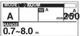 | The flash light intensity is controlled automatically according to the camera's setup. The flash will be adjusted based on the brightness taken through the camera's lens. Usually use this mode with a camera with communication capability.The flash will be adjusted based on the brightness captured by auto light receptor on the electronic flash. If the camera has communication capability, this mode can be used only when the camera is an AUTO-compatible model. |
| MANUAL |  | The flash fires at the selected output. The display shows the optimal shooting distance based on the selected output and camera settings. |
| FP TTLAUTO*1 | 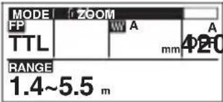 | Super FP *3 allows the flash to be used at shutter speeds faster than the flash sync speed.• displayed in [FP TTLAUTO] and [FP MANUAL] modes.• In [FP MANUAL] mode, choose the flash output. |
| FP MANUAL*2 | 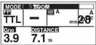 | |
| MULTI | 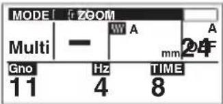 | The flash fires multiple times at a set frequency. You can choose the flash level, frequency, and the number of times the flash fires. The maximum number of times the flash can fire varies with flash level. |
| RC | 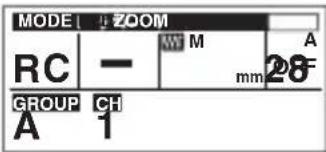 | Choose for wireless flash control. “Wireless Flash Control” (P. 30) |
| SL AUTO*4 |  | The flash fires in slave mode.• displayed in [SL AUTO] and [SL MANUAL] modes. “Slave Mode” (P. 36) |
| SL MANUAL*2 |  |
*1 Flash control operation is identical to [TTL-AUTO] mode.
*2 Flash control operation is identical to [MANUAL] mode.
*3 Maximum output is reduced, resulting in a lower flash range. Flash range also diminishes as shutter speed increases.
*4 Flash control operation is identical to [AUTO] mode.
Adjusting Settings
Using the Selector
Frequently-used options can be accessed via the selector.
| Button Function | |
| ZOOM(△) | Press ZOOM (△) button to display settings and rotate the dial to adjust the angle of illumination manually. Press OK button to put the changes into effect. “M” appears in the display when the angle of illumination is adjusted manually. |
 (◀) (◀) | Press [IMAGE] (◀) button to display settings and rotate the dial to adjust flash compensation by up to ±5. Press OK button to put the changes into effect. This value is combined with adjustments to flash compensation made using the camera. |
| [TK76](▶) | If you first press the MENU/▶(▽) button and select [Manual] for [LED Mode] (P. 34), you can turn the LED light on and off manually. Press the [▶](▶) button once to turn the LED light on and again to turn it off. A [▶] icon is displayed when the LED light is on. |
MI  (▽) (▽) | Pressing the MENU/▶(▽) button displays custom settings. See “Using the Menus” on page 34. Pressing the MENU/▶(▽) button for 2 s locks flash controls (control lock). The controls can be unlocked by again pressing the MENU/▶(▽) button for 2 s. A [▶] icon is displayed when controls are locked. The LED light function of the [▶](▶) button and the test flash function of the TEST button are not affected by control lock. |
Using the Control Panel
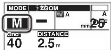
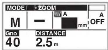
The control panel can be used to select items and choose options, for example when adjusting related settings after choosing a flash control mode using the MODE button.
1 Press the OK button.
- The most recently selected item will be highlighted.
2 Press △▽◀▶ to highlight items and press the OK button to select.
- Settings will be displayed.
3 Rotate the dial to change the highlighted item.
- Other settings (if displayed) can be selected by pressing ◀.
4 Press OK button to put the changes into effect.


Available Options
| Option Description | |
| MODE (flash control mode) | Choose the flash control mode (P. 26). |
| ZOOM (angle of illumination) Choose the angle of illumination (P. 28). | |
| §+/- (fl ash compensation) | Adjust fl ash compensation (P. 28). |
| Gno (guide number) | Adjust flash level (P. 26). |
| Hz (frequency) | Choose the frequency and number of fl ashes for MULTI mode (P. 26). |
| TIME (number of fl ashes) | |
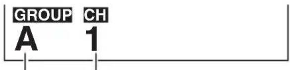
| GROUP (group) | Choose a group and communications channel for RC mode (P. 30). |
| CH (channel) | |
| ISO (ISO sensitivity) | Select the ISO sensitivity and aperture for cameras that do not exchange shooting information with the fl ash (P. 36). |
| F (aperture) | |
Wireless Flash Control
Wireless control is available with Olympus digital cameras that support RC mode. The unit is controlled by means of a flash mounted on the camera. It can also be mounted on a camera for wireless control of multiple remote flash units.
- Since the communication is performed with the flash emission of the camera, the flash positioning range varies with camera. For information on cameras that support this system, see the camera manual.
Controlling the Flash Remotely
Flash Settings
1 Select RC mode on the camera.
2 Choose [RC] as the flash control mode (P. 26).
- Press MODE and rotate the dial to select a flash control mode.

3 Use the flash to select the channel and group.
- Highlight settings using ◀▷ and rotate the dial to change.
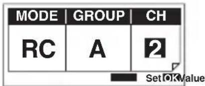
| GROUP | Group | The camera can adjust fl ash settings separately for up to 3 groups; choose the group to which the fl ash belongs. |
| CH | Channel Set | the camera and fl ash to the same channel. |
4 Press the OK button to put the changes into effect.
- Settings for each group, Including flash control mode, flash level, and flash compensation, can be adjusted from the camera.
Placing Wireless Flash Units
1 Attach the stand provided.
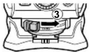
- Keeping the latch release pressed, slide the latch in the direction opposite to that shown by the [LOCK▶] arrow to undo the latch (①).

- Slide the flash securely onto the stand (2).

natural_image
Line drawing of a camera flash unit with a foot and base, no text or symbols present- Slide the latch to the [LOCK▶] position to latch the flash in place.
- To remove the flash, undo the latch and slide the unit from the stand.
2 Position the flash with the remote sensor facing the camera.
- We recommend using a single group of up to three remote flash units.
• Take a test shot after positioning. - Flash may not fire due to the angle or distance between the camera and the object.
Using the Flash to Control
Adjusting Camera and Flash Settings
1 Attach the flash to the camera (P. 24).
2 Select RC mode on the camera.
3 Choose [TTL-AUTO] as the flash control mode (P. 26).
Other Flash Options
Fixing the Irradiation Angle
Point the flash head at a wall or ceiling for bounce flash photography. The area illuminated at ranges of 0.6–1.0 m (2.0–3.3 ft.) will not be correct; point the flash down.
1 Pressing the bounce lock release button, turn the light-emitting section up/down and left/right.

Using the Wide Panel
Use for angles of illumination wider than 12 mm (24 mm in 135 format). The ZOOM display will blink if the lens focal length is under 12 mm.
1 Slide out the wide panel and place it on the light-emitting area.
- The estimated range display changes when the wide panel is used.
- Choose from angles of 10, 8, and 7 ~mm .
- Do not tilt the wide panel up.
- The ZOOM display will blink if the lens has a focal length of 12 mm or more.

natural_image
Diagram of a cylindrical device with a downward arrow indicating a component (no text or symbols present)
Using the Catch Light Plate
The catch light plate reflects light from the flash to create a catch light effect.
1 Slide out the catch light plate.
2 Pressing the bounce lock release button, angle the flash head straight up.

natural_image
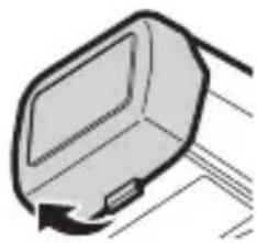
Simple line drawing of a printer with an upward arrow indicating compression (no text or symbols)Attaching the supplied bounce adapter diffuses the light from the flash over a wider area for softer bounce lighting.
- Insert the tabs on the interior of the bounce adapter into the matching slots on top of the flash and attach the adapter as shown.

- Attaching the adapter reduces flash output.
• To remove the adapter, pull the tab on the bottom toward you as shown.
natural_image
Simple line drawing of a computer monitor with an arrow indicating rotation (no text or symbols)Using the IR Filter
Attach the IR filter when using the flash to control other units in RC mode.
- Insert the tabs on the interior of the IR filter into the matching slots on top of the flash and attach the filter as shown.

- To remove the filter, pull the tab on the bottom toward you as shown.

natural_image
Pure mechanical component diagram without any text, numbers, or symbolsUsing the Menus
Use the menus to adjust settings for ease of use.
• The menu will be displayed.
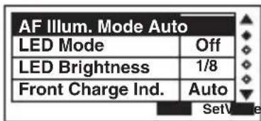
2 Use to highlight items and rotate the dial to change.
3 Press the OK button to put the changes into effect.

Available Options
Default settings shown by ____.
| Function Option Description | ||
| AF Illum. Mode (AF illuminator) | Auto The camera | controls the AF illuminator. |
| Off AF illuminator | off. | |
| LED Mode (LED light mode) | Auto | The LED light lights automatically during movie recording. |
| Manual | The LED light (▷) button turns the LED light on and off. | |
| Off LED light off. | ||
| LED Brightness (LED light brightness) | 1/1 – 1/32(Default: 1/8) | Adjust LED brightness. |
| Front Charge Ind. (charge indicator) | Auto | The LED light blinks when the fl ash is ready for use ([RC], [SL AUTO], and [SL MANUAL] modes only). |
| Off | Charge indicator disabled; the LED light does not blink when the fl ash is ready for use. | |
| Back Light Mode (backlight mode) | Auto | The backlight turns on when fl ash controls are used. |
| On | The backlight remains on at all times. | |
| Off Backlight off. | ||
| Back Light Timer (auto off timer) | 1s – 15s(Default: 5s) | Choose the time (in seconds) before the backlight turns off automatically when no operations are performed. |
| Slave Mode(slave mode display) | On Flash control | display shows slave mode. |
| Off | Flash control display does not show slave mode. | |
| Flash Cable(fl ash cable) | On Flash cable used. | |
| Off Flash cable not used. | ||
| Zoom Display(zoom display) | FT | Display focal length values for FOUR THIRDS lenses. |
| 135F Display 135 | format equivalent values. | |
| m/ft(distance units) | m Distances displayed in meters. | |
| ft Distances displayed in feet. | ||
| Wide Panel(wide panel detection) | On | Flash detects position of wide panel. Angle of illumination adjusted automatically. |
| Off Flash does not detect wide panel position. | ||
| GN(guide number display) | On | Flash output is shown as a guide number. |
| Off | Flash output is shown as a relative value.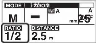 | |
| Auto Mode Source(fl ash control) | Camera | Show the flash range calculated by the camera in AUTO flash control mode. |
| Flash | Show the current aperture and ISO sensitivity. "Cameras That Do Not Communicate with the Flash" (P. 36)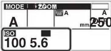 . . | |
| Reset(reset) | No | Default settings are not restored. |
| Yes | Restore default settings. | |
Cameras That Do Not Communicate with the Flash
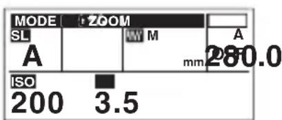
When the unit is attached to a camera that does not supply shooting information, flash output can be set to the value metered by the flash or adjusted in advance using flash controls. The unit can also be configured for use as a slave flash for use with cameras that do not offer an RC mode.
AUTO
The flash automatically adjusts flash output for optimal results.
1 Set the flash control mode to [AUTO] (P. 26).
2 Match the angle of illumination to the focal length of the lens (P. 28).
3 Select [Flash] for [Auto Mode Source] in the menu display (P. 35).
• ISO sensitivity and aperture are displayed.

4 Adjust aperture and ISO sensitivity (P. 28).
- If the selected values are out of the flash control range, [ISO] and [F] will blink in the display. The AUTO CHECK lamp blinks for about 5 s after the shutter is released to show that the flash has fired successfully.
MANUAL
Choose the guide number.
1 Set the flash control mode to [MANUAL] (P. 26).
2 Adjust flash level (P. 28).

Slave Mode
The flash can be fired remotely in sync with any flash fired by other units.
1 Set the flash control mode to [SL AUTO] or [SL MANUAL] (P. 26).
2 Position the flash.
- The flash can not be used with cameras that require a pre-flash.
- The flash may fire in response to flash units used by other photographers.
Safety precautions
Read WARNINGS and CAUTIONS thoroughly to ensure safe usage. These safety precautions protect the users and others and prevent property damage.

WARNING
Failure to observe the precautions indicated by this symbol may result in injury or death.
- Do not use flash in places where it may be exposed to flammable or explosive gas. Otherwise, fi re ignition or explosion may result.
- Do not directly solder the product or modify, remodel, or disassemble.
- Do not cover the light emitting area of the flash with your hand, and do not touch the light emitting area after continuous firing. It may burn your skin.
- Water and foreign matter inside of the device may cause fire or electric shock. If the device is immersed in or exposed to water or foreign matter is found inside of the device, turn off the power immediately and remove batteries with care. Contact your dealer or consult an Olympus Authorized Service Station.
- To prevent a traffic accident, do not direct the flash at a person operating a motor vehicle.
- Do not use the flash or AF illuminator in close proximity to others (especially infants). Keep the flash out of reach of children. Light from the flash can cause visual impairment.
- Do not use batteries that are not specified for use.
- Do not mix old and new batteries, or batteries made by different manufacturers.
- Do not connect substances such as metal to the (+) or (−) of batteries.

CAUTION
Failure to observe the precautions indicated by this symbol may result in injury or property damage.
- If you notice any abnormalities such as odor, noise, or smoke, stop using this device. Otherwise a fire or burn may result. Remove the batteries carefully to avoid burning yourself, and contact your dealer or consult an Olympus Authorized Service Station.
- Do not operate with wet hands. This may cause malfunction or electric shock.
- Do not use or store batteries in areas exposed to extremely high temperatures, such as in direct sunlight, in an enclosed vehicle on a sunny day, or near a heater.
- Continuous repeated fi ring could lead to adverse health effects.
- Dirt or water on the contacts can cause malfunction. Remove dirt, water, and other foreign matter before attaching the unit to the camera.
Specifications
| MODEL NO. FL-900R | |
| Product type External elec | electronic fl ash for digital still camera |
| Guide number 58 (ISO100), 14 (ISO100, using the wide panel) | |
| Firing angle Covers the | angle of view of 12–100 mm lenses (equivalent to 24–200 mm in 135 format)(With wide panel: 7 mm lens, equivalent to 14 mm in 135 format) |
| Flash modes TTL-AUTO, AUTO, MANUAL, FP TTLAUTO, FP MANUAL,MULTI, RC, SL AUTO, SL MANUAL | |
| Flash emission period A | Approx. 1/20000 to 1/500 seconds (except in Super FP fl ash) |
| Flash emission count(at full activation)* | Approx. 200 times (using AA (R6) NiMH batteries)Approx. 160 times (using AA (R6) alkaline batteries) |
| Recharge time Approx. | 2.5 seconds (using AA (R6) NiMH batteries)Approx. 4.5 seconds (using AA (R6) alkaline batteries)(from full activation to CHARGE lamp lighting)* |
| AF illuminator Effective range: Approximately 1–5 m (varies with camera and lens used) | |
| Liquid ingress protection (class) | Class 1 (IPX1), equivalent to JISC0920/IEC60529 (in-house measurements) |
| Operating environment | Temperature: -10 to 40°C (14 to 104°F)Humidity: 30 to 90% |
| Dimensions 81.2 (W) × | 121.4 (H) × 125.2 (D) mm/3.2 × 4.8 × 4.9 in.(excluding protrusions) |
| Weight 382 g (13.5 oz.) | (excluding batteries) |
* Measurements obtained from in-house tests at Olympus. Actual figures may vary depending on shooting conditions.
Specifications are subject to change without any notice or obligation on the part of the manufacturer.
For customers in North America, Central America, South America and the Caribbean
FCC Notice
This device complies with part 15 of the FCC rules. Operation is subject to the following two conditions: (1) This device may not cause harmful interference, and (2) this device must accept any interference received, including interference that may cause undesired operation.
Any unauthorized changes or modifications to this equipment would void the user's authority to operate.
For customers in Europe
This symbol [crossed-out wheeled bin WEEE Annex IV] indicates separate collection of waste electrical and electronic equipment in the EU countries.
Please do not throw the equipment into the domestic refuse.
Please use the return and collection systems available in your country for the disposal of this product.
Technical Support (U.S.A. / Canada)
24/7 online automated help: http://www.olympusamerica.com/support
Phone customer support: Tel.1-800-260-1625 (Toll-free)
Our phone customer support is available from 9 am to 9 pm (Monday to Friday) ET
E-Mail: distec@olympus.com
European Technical Customer Support
Please visit our homepage
http://www.olympus-europa.com
or call: Tel. 00800 - 67 10 83 00 (Toll-free)
+49 40 - 237 73 899 (Charged)
natural_image
Mechanical component diagram showing a cylindrical housing with internal components and directional arrows (no text or symbols)
natural_image
Mechanical assembly diagram showing a lever and three cylindrical components with positive and negative charges (no text or labels)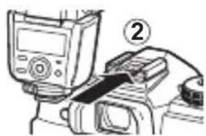
natural_image
Illustration of a device being adjusted with a belt, no text or symbols present
natural_image
Diagram of a camera with an optical lens and foot base, no text or symbols presentnatural_image
Simple line drawing of a printer with an upward arrow indicating compression (no text or symbols)natural_image
Simple line drawing of a computer monitor with an arrow indicating rotation (no text or symbols)natural_image
Pure mechanical component diagram without any text, numbers, or symbolsOptions disponibles
Mode esclave
natural_image
Mechanical component diagram showing a cylindrical housing with internal components and directional arrows (no text or symbols)
natural_image
Mechanical assembly diagram showing a lever and three cylindrical components with positive and negative charges (no text or labels)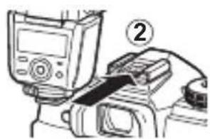
natural_image
Illustration of a device being adjusted with a belt, no text or symbols present

natural_image
Diagram of a camera with an optical lens and foot, showing no text or symbolsnatural_image
Simple line drawing of a printer with an upward arrow indicating compression (no text or symbols)natural_image
Simple line drawing of a computer monitor with an arrow indicating rotation (no text or symbols)Uso del filtro IR
natural_image
Pure mechanical component diagram without any text, numbers, or symbolsUso de los menús
Modo esclavo
natural_image
Mechanical component diagram showing a rotating assembly with arrows indicating motion (no text or symbols)
natural_image
Mechanical assembly diagram showing a motor handle and three cylindrical components with positive and negative charges (no text or labels)카메라에 장착
natural_image
Illustration of a hand holding a device with a numbered label (2), no readable text or symbols present.
natural_image
Diagram of a camera flash unit with an arrow pointing to a foot (no text or symbols present)natural_image
Illustration of a mechanical device with a downward arrow indicating a component (no text or symbols present)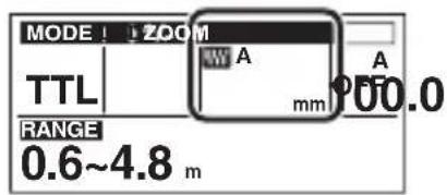
캐치 라이트 플레이트 사용
natural_image
Simple line drawing of a printer with an upward arrow indicating compression (no text or symbols)natural_image
Simple line drawing of a computer monitor with an arrow indicating rotation (no text or symbols)적외선 필터 사용
natural_image
Simple line drawing of a mechanical component or bracket (no text or symbols)메뉴 사용
사용 가능한 옵션
슬레이브 모드
제조자: OLYMPUS CORPORATION
natural_image
Mechanical component diagram showing a cylindrical housing with internal components and directional arrows (no text or symbols)
natural_image
Mechanical component diagram showing a motor, gears, and housing (no text or symbols)安裝到照相機
natural_image
Illustration of a handheld electronic device with a labeled component (no text or symbols present)
- 將顯示設定。

3 轉動撥盤更改反白顯示的項目。
natural_image
Diagram of a camera flash unit with an arrow indicating motion, no text or symbols present
natural_image
Technical line drawing of a cylindrical device with a downward arrow indicating a component (no text or symbols)natural_image
Simple line drawing of a printer with an upward arrow indicating compression (no text or symbols)使用彈射閃光轉接器
- 安裝轉接器可減少閃光輸出。
natural_image
Simple line drawing of a computer monitor with an arrow indicating rotation (no text or symbols)使用 IR 濾鏡
natural_image
Pure mechanical component diagram without any text, numbers, or symbols使用選單
使用選單可調整設定以便於使用。
1 按下 MENU/ 🔒 (▽)按钮。
- 將顯示選單。

可用選項
預設設定以 表示。
從屬模式
natural_image
Mechanical component diagram showing a cylindrical housing with internal components and directional arrows (no text or symbols)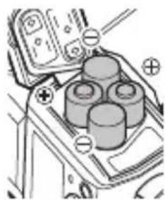
natural_image
Mechanical assembly diagram showing a piston and cylinder with positive and negative charges (no text or labels)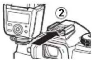

natural_image
Diagram of a camera with an optical component and foot base, no text or symbols presentnatural_image
Illustration of a cylindrical device with a downward arrow pointing to its top surface (no text or symbols)
การใช้แผ่นสะท้อนแสง
natural_image
Simple line drawing of a printer with an upward arrow indicating compression (no text or symbols)natural_image
Simple line drawing of a computer monitor with an arrow indicating rotation (no text or symbols)การใช้ฟิลเตอร์ IR
natural_image
Pure mechanical component diagram without any text, numbers, or symbolsการใช้เมนู
| AF Illum. Mode Auto | |
| LED Mode | Off |
| LED Brightness | 1/8 |
| Front Charge Ind. | Auto |
| AF Illum. Mode Auto | |
| LED Mode | Manual |
| LED Brightness | 1/8 |
| Front Charge Ind. Auto | |
ตัวเลือกที่ใช่ได้
โหมดสเลฟ
line
| Label | Value | |---|---| | Gno | 5.9 | | Hz | 10 | | TIME | 5 | ⑬ | 13 | ⑮ | 15 | ⑯ | 16 | ⑰ | | ⑱ | | ⑲ | | ⑳ | | ⑺ | | ⑳ | | ⑰ | | ⑱ | | ⑲ | | ⑳ | | ⑯ | | ⑯ | | ⑱ | | ⑲ | | ⑭ | | ⑭ | | ⑭ | | ⑯ | | ⑯ | | ⑩ | | ⑩ | | ⑩ | | ⑪ | | ⑪ | | ⑪ | | ⑪ | | ⑫ | | ⑫ | | ⑫ | | ⑫ | | ⑫ | | ⑫ | | ⑫ | | ⑫ | | ⑫ | | ⑫ | | ⑫ | | ⑫ | | ⑫ | | ⑫ | | ⑫ | | ⑫ | | ⑫ | | ⑫ | | ⑫ | | ⑫ | | ⑧ | | | Gno | 5.9 | | Hz | 10 | | TIME | 5 | ⑬ | | ⑹ | | ⑩ | | ⑪ | | ⑭ | | ⑭ | | ⑭ | | ⑭ | | ⑭ | | ⑭ | | ⑭ | | ⑭ | | ⑭ | | ⑭ | | ⑭ | | ⑭ | | ⑭ | | ⑭ | | ⑭ | | ⑭ | | ⑭ | | ⑭ | | ⑭ | | ⑭ | | ⑦ | | | Gno | 5.9 | | Hz | 10 | | TIME | 5 | ⑬ | | ⑬ | | ⑬ | | ⑬ | | ⑬ | | ⑬ | | ⑬ | | ⑬ | | ⑬ | | ⑬ | | ⑬ | | ⑬ | | (○) | (○) : (○) : (○) : (○) : (○) : (○) : (○) : (○) : (○) : (○) : (○) : (○) : (○) : (○) : (○) : (○) : (○) : (○) : (○) : (○) : (○): (○): (○): (○): (○): (○): (○): (○): (○): (○): (○): (○): (○): (○): (○): (○): (○): (○): (○): (○): (○) : (○): (○): (○): (○): (○): (○): (○): (○): (○): (○): (○): (○): (○): (○): (○): (○): (○): (○): (○) : (○) : (○) : (○) : (○) : (○) : (○) : (○) : (○) : (○) : (○) : (○) : (○) : (○) : (○) : (○) : (○) : (○) : (○) : (○) .Režim RC

natural_image
Mechanical component diagram showing a cylindrical housing with internal components and directional arrows (no text or symbols)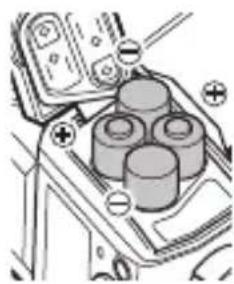
natural_image
Mechanical assembly diagram showing a piston and cylinder components with positive and negative charges (no text or labels)
natural_image
Illustration of a handheld electronic device with a labeled component (no text or symbols present)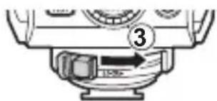

natural_image
Diagram of a camera flash unit with an arrow pointing to a foot (no text or symbols present)natural_image
Technical line drawing of a mechanical component with a downward arrow indicating a feature (no text or symbols present)
natural_image
Simple line drawing of a printer with an upward arrow indicating compression (no text or symbols)natural_image
Simple line drawing of a computer monitor with an arrow indicating rotation (no text or symbols)Použití IR filtru
natural_image
Pure mechanical component diagram without any text, numbers, or symbolsPoužití nabídek
Dostupné možnosti
MANUAL
natural_image
Mechanical component diagram showing a rotating housing with directional arrows (no text or symbols)
natural_image
Mechanical assembly diagram showing a motor with three cylinders and four wheels, no text or symbols present
Blitzsteuermodi

natural_image
Diagram of a camera flash unit with an arrow pointing to a foot (no text or symbols present)natural_image
Diagram of a mechanical component with a downward arrow indicating force or direction (no text or symbols)
natural_image
Simple line drawing of a printer with an upward arrow indicating compression (no text or symbols)natural_image
Simple line drawing of a computer monitor with an arrow indicating rotation (no text or symbols)natural_image
Pure mechanical component diagram without any text, numbers, or symbolsBenutzen der Menüs
Verfügbare Optionen
Slave-Modus
natural_image
Mechanical component diagram showing a cylindrical housing with internal components and directional arrows (no text or symbols)
natural_image
Mechanical assembly diagram showing a piston and cylinder components (no text or labels)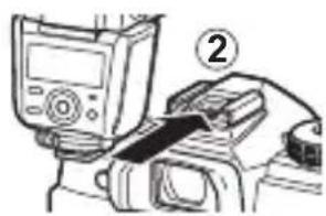
natural_image
Diagram of a camera with an optical lens and foot, showing no text or symbolsnatural_image
Diagram of a cylindrical device with a downward arrow indicating a component (no text or symbols present)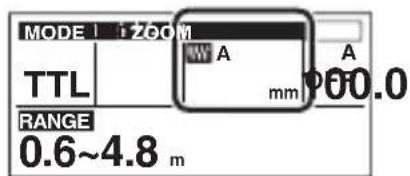
natural_image
Simple line drawing of a printer with an upward arrow indicating compression (no text or symbols)natural_image
Simple line drawing of a computer monitor with an arrow indicating rotation (no text or symbols)natural_image
Pure mechanical component diagram without any text, numbers, or symbolsOrjatilae
natural_image
Mechanical component diagram showing a cylindrical housing with internal components and directional arrows (no text or symbols)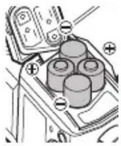
natural_image
Mechanical assembly diagram showing a motor with three wheels and a battery, no text or symbols presentnatural_image
Technical line drawing of a mechanical device with labeled component (no readable text or symbols)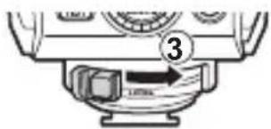
natural_image
Diagram of a camera flash unit with a foot and base, showing no text or symbolsnatural_image
Technical line drawing of a mechanical component with a downward arrow indicating a feature (no text or symbols present)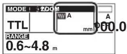
natural_image
Simple line drawing of a printer with an upward arrow indicating compression (no text or symbols)natural_image
Simple line drawing of a computer monitor with an arrow indicating rotation (no text or symbols)natural_image
Pure mechanical component diagram without any text, numbers, or symbolsKorzystanie z menu
Dostępne opcje
Tryb pomocniczy
natural_image
Mechanical component diagram showing a cylindrical housing with internal components and directional arrows (no text or symbols)
natural_image
Mechanical assembly diagram showing a motor with three cylinders and labeled terminals (no text or symbols present)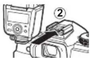
natural_image
Illustration of a medical device with a labeled connector (no text or symbols present)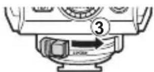
natural_image
Diagram of a camera flash unit with an arrow pointing to a foot (no text or symbols present)natural_image
Technical line drawing of a mechanical component with a downward arrow indicating a feature (no text or symbols present)
natural_image
Simple line drawing of a printer with an upward arrow indicating compression (no text or symbols)natural_image
Simple line drawing of a computer monitor with an arrow indicating rotation (no text or symbols)natural_image
Pure mechanical component diagram without any text, numbers, or symbolsИспользование меню
| AF Illum. Mode Auto | |
| LED Mode | Off |
| LED Brightness | 1/8 |
| Front Charge Ind. | Auto |
| AF Illum. Mode Auto | |
| LED Mode | Manual |
| LED Brightness | 1/8 |
| Front Charge Ind. Auto | |
Доступные опции
- IMPORTANT SAFETY INSTRUCTIONS
- SAVE THESE INSTRUCTIONS
- カメラに取り付ける
- ダイヤルを回して設定を変更する
- バウンスアダプターを使う
- IR フィルターを使う
- メニューの設定
- 設定できる機能
- スレーブ
- 安全上のご注意
- Names of Parts
- Readying the Flash
- Preparing a Battery (Sold S
- Loading Batteries
- Attaching to the Camera
- Press the ON/OFF button.
- Basic Photography and Settings
- Shooting
- Test Flash
- Choosing a Flash Control Mode
- Adjusting Settings
- Using the Selector
- Using the Control Panel
- Wireless Flash Control
- Controlling the Flash Remotely
- Flash Settings
- Placing Wireless Flash Units
- Using the Flash to Control
- Adjusting Camera and Flash Settings
- Other Flash Options
- Fixing the Irradiation Angle
- Using the Wide Panel
- Using the Catch Light Plate
- Using the IR Filter
- Using the Menus
- Available Options
- Cameras That Do Not Communicate with the Flash
- AUTO
- MANUAL
- Slave Mode
- Safety precautions
- WARNING
- CAUTION
- Specifications
- For customers in North America, Central America, South America and the Caribbean
- For customers in Europe
- Technical Support (U.S.A. / Canada)
- European Technical Customer Support
- Options disponibles
- Mode esclave
- Uso del filtro IR
- Uso de los menús
- Modo esclavo
- 카메라에 장착
- 캐치 라이트 플레이트 사용
- 적외선 필터 사용
- 메뉴 사용
- 사용 가능한 옵션
- 슬레이브 모드
- 安裝到照相機
- 使用彈射閃光轉接器
- 使用 IR 濾鏡
- 使用選單
- 可用選項
- 從屬模式
- การใช้แผ่นสะท้อนแสง
- การใช้ฟิลเตอร์ IR
- การใช้เมนู
- ตัวเลือกที่ใช่ได้
- โหมดสเลฟ
- Použití IR filtru
- Použití nabídek
- Dostupné možnosti
- Benutzen der Menüs
- Verfügbare Optionen
- Slave-Modus
- Orjatilae
- Korzystanie z menu
- Dostępne opcje
- Tryb pomocniczy
- Использование меню
- Доступные опции
Brand : OLYMPUS
Model : FL‑900R
Category : Flash