
BGA450 - Garden shredder MAKITA - Free user manual and instructions
Find the device manual for free BGA450 MAKITA in PDF.
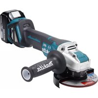
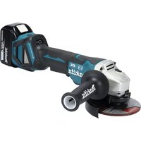
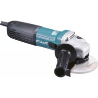
| Product Type | Cordless Angle Grinder |
| Brand | Makita |
| Model | BGA450 |
| Wheel Diameter | 115 mm |
| No Load Speed | 10 000 min⁻¹ |
| Overall Length | 317 mm |
| Net Weight | 1.9 kg |
| Rated Voltage | DC 14.4 V |
| Power Source | Li-ion Battery (not included) |
| Shaft Thread | M14 |
| Main Uses | Grinding, sanding and cutting of metals and stones without water |
| Switch | Slide switch with lock-on function for continuous use |
| Shaft Lock | Yes, for easy wheel change |
| Protective Guard | Yes, adjustable |
| Multi-function Indicator | Indicates battery status and overload |
| Accidental Restart Protection | Yes |
| Side Handle | Yes, removable |
| Maintenance and Cleaning | Clean ventilation slots regularly; replace carbon brushes when they reach the limit mark |
| Spare Parts and Repairability | Replaceable carbon brushes; repairs by Makita authorized service center |
| Included Accessories | Lock nut wrench, wheel guard, side handle |
| Sound Level | 75 dB(A) (sound pressure); may exceed 85 dB(A) in use |
Frequently Asked Questions - BGA450 MAKITA
User questions about BGA450 MAKITA
0 question about this device. Answer the ones you know or ask your own.
Ask a new question about this device
Download the instructions for your Garden shredder in PDF format for free! Find your manual BGA450 - MAKITA and take your electronic device back in hand. On this page are published all the documents necessary for the use of your device. BGA450 by MAKITA.
USER MANUAL BGA450 MAKITA
GB Cordless Angle Grinding Instruction manual
F Meuleuse d'angle sans fil Manuel d'instructions
D Akku-Winkelschleifer Betriebsanleitung
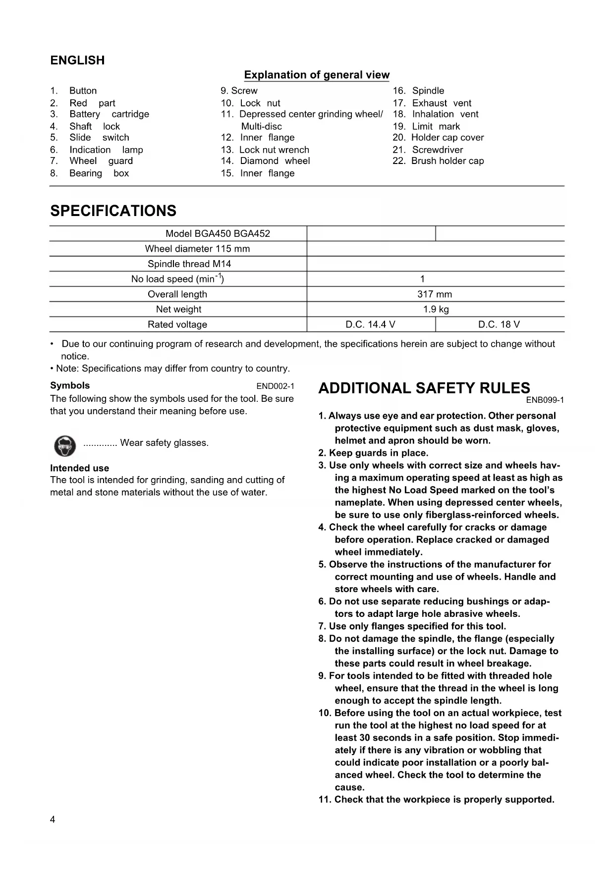
Explanation of general view
| 1. | Button | 9. | Screw | 16. | Spindle |
| 2. | Red part | 10. | Lock nut | 17. | Exhaust vent |
| 3. | Battery cartridge | 11. | Depressed center grinding wheel/ | 18. | Inhalation vent |
| 4. | Shaft lock | Multi-disc | 19. | Limit mark | |
| 5. | Slide switch | 12. | Inner flange | 20. | Holder cap cover |
| 6. | Indication lamp | 13. | Lock nut wrench | 21. | Screwdriver |
| 7. | Wheel guard | 14. | Diamond wheel | 22. | Brush holder cap |
| 8. | Bearing box | 15. | Inner flange |
SPECIFICATIONS
| Model BGA450 BGA452 | ||
| Wheel diameter 115 mm | ||
| Spindle thread M14 | ||
| No load speed (min-1) | 1 | |
| Overall length | 317 mm | |
| Net weight | 1.9 kg | |
| Rated voltage | D.C. 14.4 V | D.C. 18 V |
- Due to our continuing program of research and development, the specifications herein are subject to change without notice.
Note: Specifications may differ from country to country.
Symbols
END002-1
The following show the symbols used for the tool. Be sure that you understand their meaning before use.

Wear safety glasses.
Intended use
The tool is intended for grinding, sanding and cutting of metal and stone materials without the use of water.
ADDITIONAL SAFETY RULES
ENB099-1
- Always use eye and ear protection. Other personal protective equipment such as dust mask, gloves, helmet and apron should be worn.
- Keep guards in place.
- Use only wheels with correct size and wheels having a maximum operating speed at least as high as the highest No Load Speed marked on the tool's nameplate. When using depressed center wheels, be sure to use only fiberglass-reinforced wheels.
- Check the wheel carefully for cracks or damage before operation. Replace cracked or damaged wheel immediately.
- Observe the instructions of the manufacturer for correct mounting and use of wheels. Handle and store wheels with care.
- Do not use separate reducing bushings or adaptors to adapt large hole abrasive wheels.
- Use only flanges specified for this tool.
- Do not damage the spindle, the flange (especially the installing surface) or the lock nut. Damage to these parts could result in wheel breakage.
- For tools intended to be fitted with threaded hole wheel, ensure that the thread in the wheel is long enough to accept the spindle length.
- Before using the tool on an actual workpiece, test run the tool at the highest no load speed for at least 30 seconds in a safe position. Stop immediately if there is any vibration or wobbling that could indicate poor installation or a poorly balanced wheel. Check the tool to determine the cause.
-
Check that the workpiece is properly supported.
-
Hold the tool firmly.
- Keep hands away from rotating parts.
- Make sure the wheel is not contacting the workpiece before the switch is turned on.
- Use the specified surface of the wheel to perform the grinding.
- Do not use cutting off wheel for side grinding.
- Watch out for flying sparks. Hold the tool so that sparks fly away from you and other persons or flammable materials.
- Pay attention that the wheel continues to rotate after the tool is switched off.
- Do not touch the workpiece immediately after operation; it may be extremely hot and could burn your skin.
- Do not use the tool on any materials containing asbestos.
- Do not use water or grinding lubricant.
- When use cut-off wheel, always work with the dust collecting wheel guard required by domestic regulation.
- Cutting discs must not be subjected to any lateral pressure.
SAVE THESE INSTRUCTIONS.
IMPORTANT SAFETY INSTRUCTIONS
ENC007-2
FOR BATTERY CARTRIDGE
- Before using battery cartridge, read all instructions and cautionary markings on (1) battery charger, (2) battery, and (3) product using battery.
- Do not disassemble battery cartridge.
- If operating time has become excessively shorter, stop operating immediately. It may result in a risk of overheating, possible burns and even an explosion.
- If electrolyte gets into your eyes, rinse them out with clear water and seek medical attention right away. It may result in loss of your eyesight.
- Do not short the battery cartridge:
(1) Do not touch the terminals with any conductive material.
(2) Avoid storing battery cartridge in a container with other metal objects such as nails, coins, etc.
(3) Do not expose battery cartridge to water or rain. A battery short can cause a large current flow, overheating, possible burns and even a breakdown.
- Do not store the tool and battery cartridge in locations where the temperature may reach or exceed 50^ (122^) .
- Do not incinerate the battery cartridge even if it is severely damaged or is completely worn out. The battery cartridge can explode in a fire.
- Be careful not to drop or strike battery.
SAVE THESE INSTRUCTIONS.
Tips for maintaining maximum battery life
- Charge the battery cartridge before completely discharged. Always stop tool operation and charge the battery cartridge when you notice less tool power.
- Never recharge a fully charged battery cartridge. Overcharging shortens the battery service life.
- Charge the battery cartridge with room temperature at 10^ - 40^ (50^ - 104^) . Let a hot battery cartridge cool down before charging it.
SAVE THESE INSTRUCTIONS.
FUNCTIONAL DESCRIPTION
CAUTION:
- Always be sure that the tool is switched off and the battery cartridge is removed before adjusting or checking function on the tool.
Installing or removing battery cartridge (Fig. 1)
- Always switch off the tool before insertion or removal of the battery cartridge.
- To remove the battery cartridge, withdraw it from the tool while sliding the button on the front of the cartridge.
- To insert the battery cartridge, align the tongue on the battery cartridge with the groove in the housing and slip it into place. Always insert it all the way until it locks in place with a little click. If you can see the red part on the upper side of the button, it is not locked completely. Insert it fully until the red part cannot be seen. If not, it may accidentally fall out of the tool, causing injury to you or someone around you.
- Do not use force when inserting the battery cartridge. If the cartridge does not slide in easily, it is not being inserted correctly.
Shaft lock (Fig. 2)
CAUTION:
- Never actuate the shaft lock when the spindle is moving. The tool may be damaged.
Press the shaft lock to prevent spindle rotation when installing or removing accessories.
Switch action (Fig. 3)
CAUTION:
- Before inserting the battery cartridge into the tool, always check to see that the slide switch actuates properly and returns to the "OFF" position when the rear of the slide switch is depressed.
To start the tool, slide the slide switch toward the "I (ON)" position. For continuous operation, press the front of the slide switch to lock it.
To stop the tool, press the rear of the slide switch, then slide it toward the "O (OFF)" position.
Indication lamp with multi function (Fig. 4)
Indication lamps are located in two positions.
When the battery cartridge is inserted on the tool with the slide switch positioned in the "O (OFF)" position, the indication lamp flickers quickly for approximately one second. If it does not flicker so, the battery cartridge or indication lamp has broken.
- Overload protection
- When the tool is overloaded, the indication lamp lights up. When the load on the tool is reduced, the lamp goes out.
- If the tool continues to be overloaded and the indication lamp continues to light up for approximately two seconds, the tool stops. This prevents the motor and its related parts from being damaged.
- In this case, to start the tool again, move the slide switch to the "O (OFF)" position once and then to the "I (ON)" position.
- Battery cartridge replacing signal
- When the remaining battery capacity gets small, the indicator lamp lights up during operation earlier than enough capacity battery use.
- Accidental re-start preventive function
- Even if the battery cartridge is inserted on the tool with the slide switch in the "I (ON)" position, the tool does not start. At this time, the lamp flickers slowly and this shows that the accidental re-start preventive function is at work.
- To start the tool, first slide the slide switch toward the "O (OFF)" position and then slide it toward the "I (ON)" position.
ASSEMBLY
CAUTION:
- Always be sure that the tool is switched off and the battery cartridge is removed before carrying out any work on the tool.
Installing side grip (handle) (Fig. 5)
CAUTION:
- Always be sure that the side grip is installed securely before operation.
Screw the side grip securely on the position of the tool as shown in the figure.
Installing or removing wheel guard (Fig. 6)
CAUTION:
- When using a depressed center grinding wheel/Multidisc, flex wheel, wire wheel brush, cut-off wheel or diamond wheel, the wheel guard must be fitted on the tool so that the closed side of the guard always points toward the operator.
Mount the wheel guard with the protrusion on the wheel guard band aligned with the notch on the bearing box.
Then rotate the wheel guard around 180 degrees. Be sure to tighten the screw securely.
To remove wheel guard, follow the installation procedure in reverse.
Installing or removing depressed center grinding wheel/Multi-disc
WARNING:
- Always use supplied guard when depressed center grinding wheel/Multi-disc is on tool. Wheel can shatter during use and guard helps to reduce chances of personal injury.
Mount the inner flange onto the spindle. Fit the wheel/disc on the inner flange and screw the lock nut onto the spindle. (Fig. 7)
To tighten the lock nut, press the shaft lock firmly so that the spindle cannot revolve, then use the lock nut wrench and securely tighten clockwise. (Fig. 8)
To remove the wheel, follow the installation procedure in reverse.
Installing or removing diamond wheel (optional accessory) (Fig. 9)
CAUTION:
- Make sure that the arrow on the tool should point in the same direction as the arrow on the diamond wheel.
Mount the inner flange onto the spindle. Fit the diamond wheel on over the inner flange and screw the lock nut onto the spindle. Notice that flat side of the lock nut should face the diamond wheel in case the diamond wheel is used.
WARNING:
- Only actuate the shaft lock when the spindle is not moving.
OPERATION
WARNING:
- It should never be necessary to force the tool. The weight of the tool applies adequate pressure. Forcing and excessive pressure could cause dangerous wheel breakage.
- ALWAYS replace wheel if tool is dropped while grinding.
- NEVER bang or hit grinding disc or wheel onto work.
- Avoid bouncing and snagging the wheel, especially when working corners, sharp edges etc. This can cause loss of control and kickback.
- NEVER use tool with wood cutting blades and other sawblades. Such blades when used on a grinder frequently kick and cause loss of control leading to personal injury.
CAUTION:
- Make the depth of a single cut up to 5mm . Adjust pressure on the tool so that the tool does not slow down during the operation.
-
After operation, always switch off the tool and wait until the wheel has come to a complete stop before putting the tool down.
-
If the tool is operated continuously until the battery cartridge has discharged, allow the tool to rest for 15 minutes before proceeding with a fresh battery.
Grinding and sanding operation (Fig. 10)
ALWAYS hold the tool firmly with one hand on housing and the other on the side handle. Turn the tool on and then apply the wheel or disc to the workpiece.
In general, keep the edge of the wheel or disc at an angle of about 15 degrees
to the workpiece surface.
During the break-in period with a new wheel, do not work the grinder in the B direction or it will cut into the workpiece. Once the edge of the wheel has been rounded off by use, the wheel may be worked in both A and B direction.
Operation with diamond wheel (accessory)
WARNING:
- Forcing and exerting excessive pressure or allowing the wheel to bend, pinch or twist in the cut can cause overheating of the motor and dangerous kickback of the tool.
CAUTION:
- After cutting operation, make sure that the diamond wheel stops revolving completely. Then, place the tool. It is dangerous to place the tool before turning off the tool. If there are dust or dirt around the tool, the tool may suck in them.
Be sure that the wheel does not contact the workpiece. Turn the tool on and hold the tool firmly. Wait until the wheel attains full speed. Now simply move the tool forward over the workpiece surface, keeping it flat and advancing smoothly until the cutting is completed.
MAINTENANCE
CAUTION:
- Always be sure that the tool is switched off and the battery cartridge is removed before attempting to perform inspection or maintenance.
The tool and its air vents have to be kept clean. Regularly clean the tool's air vents or whenever the vents start to become obstructed. (Fig. 11)
Replacing carbon brushes
Remove and check the carbon brushes regularly. Replace when they wear down to the limit mark. Keep the carbon brushes clean and free to slip in the holders. Both carbon brushes should be replaced at the same time. Use only identical carbon brushes. (Fig. 12)
Insert the top end of slotted bit screwdriver into the notch in the tool and remove the holder cap cover by lifting it up. (Fig. 13)
Use a screwdriver to remove the brush holder caps. Take out the worn carbon brushes, insert the new ones and secure the brush holder caps. (Fig. 14)
Reinstall the holder cap cover on the tool.
To maintain product SAFETY and RELIABILITY, repairs, any other maintenance or adjustment should be performed by Makita Authorized Service Centers, always using Makita replacement parts.
ACCESSORIES
CAUTION:
- These accessories or attachments are recommended for use with your Makita tool specified in this manual. The use of any other accessories or attachments might present a risk of injury to persons. Only use accessory or attachment for its stated purpose.
If you need any assistance for more details regarding these accessories, ask your local Makita Service Center.
- Wheel guard (Wheel cover)
- Inner flange
115 mm Depressed center wheels - Lock nut (For depressed center wheel)
Rubber pad - Abrasive discs
- Lock nut (For abrasive disc)
- Lock nut wrench
Wire cup brush
Wire bevel brush 85 - Side grip
- Dust collecting wheel guard
115 mm Diamond wheel - Various type of Makita genuine batteries and chargers
FRANÇAIS
Descriptif
EC-DECLARATION OF CONFORMITY
We declare under our sole responsibility that this product is in compliance with the following standards of standardized documents, EN60745, EN55014 in accordance with Council Directives, 89/336/EEC, 98/37/EC.
FRANÇAIS
DECLARATION DE CONFORMITE CE
Michigan Drive, Tongwell, Milton Keynes,
Bucks MK15 8JD, ENGLAND
Responsible manufacturer: Produttore responsable:
EU-DEKLARATION OM KONFORMITET
Michigan Drive, Tongwell, Milton Keynes,
Bucks MK15 8JD, ENGLAND
For European countries only
Noise and Vibration
The typical A-weighted sound pressure level is 75 dB (A). Uncertainty is 3 dB (A).
The noise level under working may exceed 85 dB (A).
- Wear ear protection. -
The typical weighted root mean square acceleration value is 3m / s^2
These values have been obtained according to EN60745.
FRANÇAIS
De afwijking is 3 dB (A).
Michigan Drive, Tongwell, Milton Keynes,
Bucks MK15 8JD, ENGLAND
Responsible manufacturer: Produtore responsable:
Michigan Drive, Tongwell, Milton Keynes,
Bucks MK15 8JD, ENGLAND

- GB Cordless Angle Grinding Instruction manual
- Explanation of general view
- SPECIFICATIONS
- Symbols
- Intended use
- ADDITIONAL SAFETY RULES
- SAVE THESE INSTRUCTIONS.
- IMPORTANT SAFETY INSTRUCTIONS
- FOR BATTERY CARTRIDGE
- Tips for maintaining maximum battery life
- FUNCTIONAL DESCRIPTION
- CAUTION:
- Installing or removing battery cartridge (Fig. 1)
- Shaft lock (Fig. 2)
- Switch action (Fig. 3)
- Indication lamp with multi function (Fig. 4)
- - Overload protection
- - Battery cartridge replacing signal
- - Accidental re-start preventive function
- ASSEMBLY
- Installing side grip (handle) (Fig. 5)
- Installing or removing wheel guard (Fig. 6)
- Installing or removing depressed center grinding wheel/Multi-disc
- WARNING:
- Installing or removing diamond wheel (optional accessory) (Fig. 9)
- OPERATION
- Grinding and sanding operation (Fig. 10)
- Operation with diamond wheel (accessory)
- MAINTENANCE
- Replacing carbon brushes
- ACCESSORIES
- FRANÇAIS
- Descriptif
- EC-DECLARATION OF CONFORMITY
- DECLARATION DE CONFORMITE CE
- EU-DEKLARATION OM KONFORMITET
- For European countries only
- Noise and Vibration
Brand : MAKITA
Model : BGA450
Category : Garden shredder