
DLW140 - Garden shredder MAKITA - Free user manual and instructions
Find the device manual for free DLW140 MAKITA in PDF.

| Product type | Cordless metal miter saw |
| Brand | Makita |
| Model | DLW140 |
| Wheel diameter | 355 mm |
| Arbor diameter | 25.4 mm |
| Max. wheel thickness | 3 mm |
| No-load speed | 3,800 min⁻¹ |
| Rated voltage | 36 V DC |
| Dimensions (L x W x H) | 537 x 290 x 640 mm (European guard) |
| Net weight | 17.2 to 17.8 kg (European guard) |
| Compatible battery | BL1815N / BL1820B / BL1830B / BL1840B / BL1850B / BL1860B |
| Compatible charger | DC18RC / DC18RD / DC18RE / DC18SD / DC18SE / DC18SF / DC18SH / DC18WC |
| Sound pressure level | 103 dB (A) |
| Sound power level | 115 dB (A) |
| Vibration (total value) | 2.5 m/s² |
| Max. cutting capacity (90°) | 137 x 137 mm (square), Ø127 mm (round) |
| Max. cutting capacity (45°) | 106 x 106 mm (square), Ø127 mm (round) |
| Electronic functions | Soft start, overload/overheat/discharge protection |
| Safety | Safety button, lock pin, protective guard |
| Maintenance | Clean ventilation slots regularly, have repairs done by an authorized center |
| Included accessories | Cut-off wheel, wrench, vise, safety guard (depending on model) |
| Usage | Cutting of ferrous materials |
| Warranty | See manual (varies by country) |
Frequently Asked Questions - DLW140 MAKITA
User questions about DLW140 MAKITA
0 question about this device. Answer the ones you know or ask your own.
Ask a new question about this device
Download the instructions for your Garden shredder in PDF format for free! Find your manual DLW140 - MAKITA and take your electronic device back in hand. On this page are published all the documents necessary for the use of your device. DLW140 by MAKITA.
USER MANUAL DLW140 MAKITA
natural_image
Three technical line drawings of metal cutting machines (no text or symbols)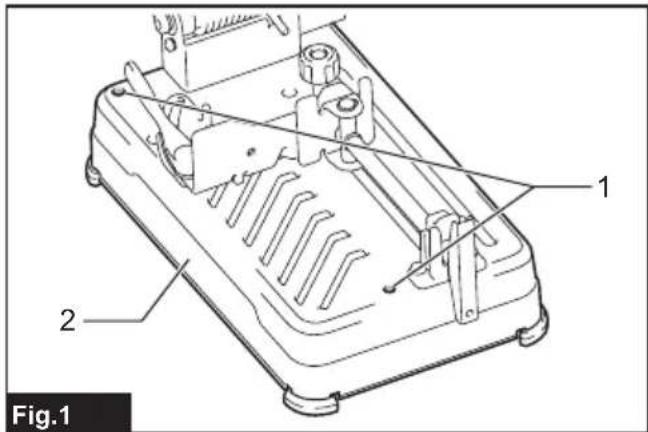
natural_image
Technical line drawing of a mechanical assembly with labeled components (no text or symbols beyond labels)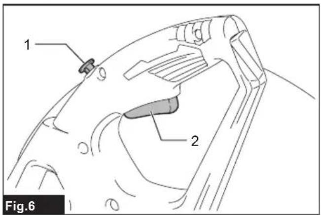
natural_image
Mechanical assembly diagram showing a rotating component with motion arrows (no text or symbols)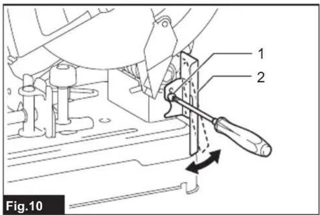
natural_image
Mechanical assembly diagram showing a rotating component with motion arrows (no text or symbols)
natural_image
Technical line drawing of a mechanical assembly with labeled component 1 (no text or symbols beyond label)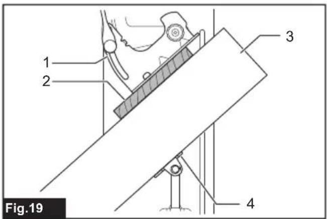
natural_image
Technical line drawing of a mechanical assembly with screws and a central component (no text or symbols)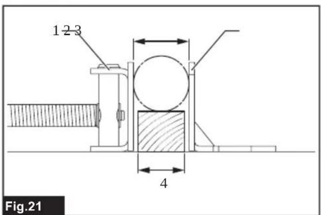

natural_image
Technical line drawing of a mechanical device with labeled components (no text or symbols beyond label)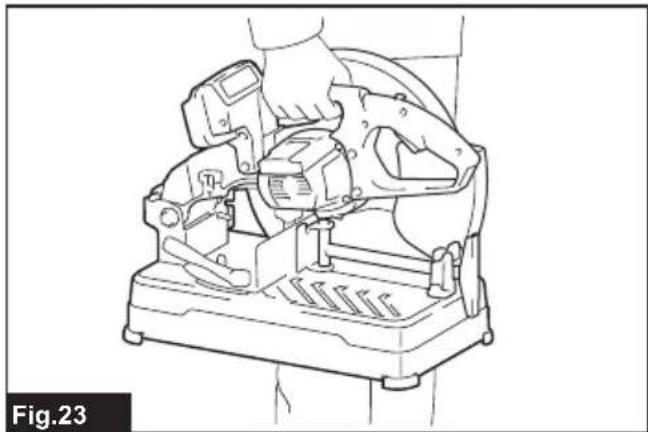
natural_image
Technical line drawing of a mechanical device with no visible text or symbolsSPECIFICATIONS
| Model: DLW140 | ||
| Wheel diameter 355 mm | ||
| Hole diameter 25.4 mm | ||
| Max. wheel thickness 3 mm | ||
| No load speed 3,800 min | -1 | |
| Rated voltage D.C. 36 V | ||
| Dimensions(L x W x H) | With European type safety guard | 537 mm x 290 mm x 640 mm |
| With safety guard other than European type | 537 mm x 280 mm x 640 mm | |
| With center cap type safety guard | 537 mm x 280 mm x 640 mm | |
| Net weight With European type safety guard | 17.2 - 17.8 kg | |
| With safety guard other than European type | ||
| With center cap type safety guard | ||
- Due to our continuing program of research and development, the specifications herein are subject to change without notice.
• Specifications may differ from country to country.
- The net weight value includes the lightest and heaviest combination of the attachment(s) for normal and safe use and battery cartridge(s) which are specified in the instruction manual.
- The shape and weight vary depending on the specifications which differ country to country.
Applicable battery cartridge and charger
| Battery cartridge BL1815N / BL1820B / BL1830B / BL1840B / BL1850B / BL1860B | |
| Charger DC18RC / DC18RD / DC18RE / DC18SD / DC18SE / DC18SF /DC18SH / DC18WC |
- Some of the battery cartridges and chargers listed above may not be available depending on your region of residence.

WARNING: Only use the battery cartridges and chargers listed above. Use of any other battery cartridges I chargers may cause injury and/or fire.
Intended use
The tool is intended for cutting in ferrous materials with appropriate abrasive cut-off wheel. Follow all laws and regulations regarding dust and work area health and safety in your country.
Noise
NOTE: The declared noise emission value(s) has been measured in accordance with a standard test method and may be used for comparing one tool with another.
NOTE: The declared noise emission value(s) can also be used in a preliminary assessment of exposure.
The typical A-weighted noise level determined according to EN62841-3-10:
Sound pressure level (L pA ) : 103 dB (A)
Sound power level ( LWA ): 115 dB (A)
Uncertainty (K) : 3 dB (A)
WARNING: Wear ear protection.
⚠ WARNING: The noise emission during actual use of the power tool can differ from the declared total value(s) depending on the ways in which the tool is used.
⚠ WARNING: Be sure to identify safety measures to protect the operator that are based on an estimation of exposure in the actual conditions of use (taking account of all parts of the operating cycle such as the times when the tool is switched off and when it is running idle in addition to the trigger time).
Vibration
The continuous vibration total value (tri-axial vector sum) determined according to EN62841-3-10:
Vibration emission (ah):2.5m / s2
Uncertainty (K) : 1.5 m/s
NOTE: The declared vibration total value(s) has been measured in accordance with a standard test method and may be used for comparing one tool with another.
NOTE: The declared vibration total value(s) can also be used in a preliminary assessment of exposure.
⚠ WARNING: The vibration emission during actual use of the power tool can differ from the declared total value(s) depending on the ways in which the tool is used.
⚠ WARNING: Be sure to identify safety measures to protect the operator that are based on an estimation of exposure in the actual conditions of use (taking account of all parts of the operating cycle such as the times when the tool is switched off and when it is running idle in addition to the trigger time).
Declarations of Conformity
For European countries only
The EU Declaration of Conformity can be accessed from the following URL.

https://support.makita.biz/doc/doc_index.html
For the UK
The Declaration of conformity is included in Annex A to this instruction manual.
SAFETY WARNINGS
General power tool safety warnings
⚠ WARNING Read all safety warnings, instructions, illustrations and specifications provided with this power tool. Failure to follow all instructions listed below may result in electric shock, fire and/or serious injury.
Save all warnings and instructions for future reference.
The term "power tool" in the warnings refers to your mains-operated (corded) power tool or battery-operated (cordless) power tool.
Cut-off machine safety warnings
- Position yourself and bystanders away from the plane of the rotating wheel. The guard helps to protect the operator from broken wheel fragments and accidental contact with wheel.
- Use only bonded reinforced cut-off wheels for your power tool. Just because an accessory can be attached to your power tool, it does not assure safe operation.
- The rated speed of the accessory must be at least equal to the maximum speed marked on the power tool. Accessories running faster than their rated speed can break and fly apart.
- Wheels must be used only for recommended applications. For example: do not grind with the side of a cut-off wheel. Abrasive cut-off wheels are intended for peripheral grinding, side forces applied to these wheels may cause them to shatter.
- Always use undamaged wheel flanges that are of correct diameter for your selected wheel. Proper wheel flanges support the wheel thus reducing the possibility of wheel breakage.
- The outside diameter and the thickness of your accessory must be within the capacity rating of your power tool. Incorrectly sized accessories cannot be adequately guarded or controlled.
- The arbour size of wheels and flanges must properly fit the spindle of the power tool. Wheels and flanges with arbour holes that do not match the mounting hardware of the power tool will run out of balance, vibrate excessively and may cause loss of control.
- Do not use damaged wheels. Before each use, inspect the wheels for chips and cracks. If the power tool or wheel is dropped, inspect for damage or install an undamaged wheel. After inspecting and installing the wheel, position yourself and bystanders away from the plane of the rotating wheel and run the power tool at maximum no load speed for one minute. Damaged wheels will normally break apart during this test time.
- Wear personal protective equipment. Depending on application, use face shield, safety goggles or safety glasses. As appropriate, wear dust mask, hearing protectors,
gloves and shop apron capable of stopping small abrasive or workpiece fragments. The eye protection must be capable of stopping flying debris generated by various operations. The dust mask or respirator must be capable of filtrating particles generated by your operation. Prolonged exposure to high intensity noise may cause hearing loss.
- Keep bystanders a safe distance away from work area. Anyone entering the work area must wear personal protective equipment. Fragments of workpiece or of a broken wheel may fly away and cause injury beyond immediate area of operation.
- Regularly clean the power tool's air vents. The motor's fan can draw the dust inside the housing and excessive accumulation of powdered metal may cause electrical hazards.
- Do not operate the power tool near flammable materials. Do not operate the power tool while placed on a combustible surface such as wood. Sparks could ignite these materials.
- Do not use accessories that require liquid coolants. Using water or other liquid coolants may result in electrocution or shock.
Kickback and related warnings
Kickback is a sudden reaction to a pinched or snagged rotating wheel. Pinching or snagging causes rapid stalling of the rotating wheel which in turn causes the uncontrolled cutting unit to be forced upwards toward the operator.
For example, if an abrasive wheel is snagged or pinched by the workpiece, the edge of the wheel that is entering into the pinch point can dig into the surface of the material causing the wheel to climb out or kick out. Abrasive wheels may also break under these conditions.
Kickback is the result of power tool misuse and/or incorrect operating procedures or conditions and can be avoided by taking proper precautions as given below.
- Maintain a firm grip on the power tool and position your body and arm to allow you to resist kickback forces. The operator can control upward kickback forces, if proper precautions are taken.
- Do not position your body in line with the rotating wheel. If kickback occurs, it will propel the cutting unit upwards toward the operator.
- Do not attach a saw chain, woodcarving blade, segmented diamond wheel with a peripheral gap greater than 10 mm or toothed saw blade. Such blades create frequent kickback and loss of control.
- Do not "jam" the wheel or apply excessive pressure. Do not attempt to make an excessive depth of cut. Overstressing the wheel increases the loading and susceptibility to twisting or binding of the wheel in the cut and the possibility of kick-back or wheel breakage.
- When the wheel is binding or when interrupting a cut for any reason, switch off the power tool and hold the cutting unit motionless until the wheel comes to a complete stop. Never attempt to remove the wheel from the cut while the wheel is in motion otherwise kickback may
occur. Investigate and take corrective action to eliminate the cause of wheel binding.
- Do not restart the cutting operation in the workpiece. Let the wheel reach full speed and carefully re-enter the cut. The wheel may bind, walk up or kickback if the power tool is restarted in the workpiece.
- Support any oversized workpiece to minimize the risk of wheel pinching and kickback. Large workpieces tend to sag under their own weight. Supports must be placed under the workpiece near the line of cut and near the edge of the workpiece on both sides of the wheel.
Additional safety warnings
- Watch out for flying sparks when operating. They can cause injury or ignite combustible materials.
- Secure work. Use clamps or a vise to hold work when practical. It's safer than using your hand and it frees both hands to operate tool.
- Secure the cut-off wheel carefully.
- Be careful not to damage the spindle, flanges (especially the installing surface) or bolt, or the cut-off wheel itself might break.
- Keep guards in place and in working order.
- Hold the handle firmly.
- Keep hands away from rotating parts.
- Make sure the cut-off wheel is not contacting the work-piece before the switch is turned on.
- Before each use, watch for flutter or excessive vibration that might be caused by poor installation or a poorly balanced wheel.
- Remove material or debris from the area that might be ignited by sparks. Be sure that others are not in the path of the sparks. Keep a proper, charged fire extinguisher closely available.
- If the cut-off wheel stops during the operation, makes an odd noise or begins to vibrate, switch off the tool immediately.
- Always switch off and wait for the cut-off wheel to come to a complete stop before removing, securing workpiece, working vise, changing work position, angle or the cut-off wheel itself.
- Do not touch the workpiece immediately after operation; it is extremely hot and could burn your skin.
- Store wheels in a dry location only.
SAVE THESE INSTRUCTIONS.
Important safety instructions for battery cartridge
- Before using battery cartridge, read all instructions and cautionary markings on (1) battery charger, (2) battery, and (3) product using battery.
- Do not disassemble or tamper with the battery cartridge. It may result in a fire, excessive heat, or explosion.
- If operating time has become excessively shorter, stop operating immediately. It may result in a risk of overheating, possible burns
and even an explosion.
-
If electrolyte gets into your eyes, rinse them out with clear water and seek medical attention right away. It may result in loss of your eyesight.
-
Do not short the battery cartridge:
(1) Do not touch the terminals with any conductive material.
(2) Avoid storing battery cartridge in a container with other metal objects such as nails, coins, etc.
(3) Do not expose battery cartridge to water or rain.
A battery short can cause a large current flow, overheating, possible burns and even a breakdown.
-
Do not store and use the tool and battery cartridge in locations where the temperature may reach or exceed 50 °C (122 °F).
-
Do not incinerate the battery cartridge even if it is severely damaged or is completely worn out. The battery cartridge can explode in a fire.
-
Do not nail, cut, crush, throw, drop the battery cartridge, or hit against a hard object to the battery cartridge. Such conduct may result in a fire, excessive heat, or explosion.
-
Do not use a damaged battery.
-
The contained lithium-ion batteries are subject to the Dangerous Goods Legislation requirements.
For commercial transports e.g. by third parties, forwarding agents, special requirement on packaging and labeling must be observed. For preparation of the item being shipped, consulting an expert for hazardous material is required. Please also observe possibly more detailed national regulations.
Tape or mask off open contacts and pack up the battery in such a manner that it cannot move around in the packaging. -
When disposing the battery cartridge, remove it from the tool and dispose of it in a safe place. Follow your local regulations relating to disposal of battery.
- Use the batteries only with the products specified by Makita. Installing the batteries to non-compliant products may result in a fire, excessive heat, explosion, or leak of electrolyte.
- If the tool is not used for a long period of time, the battery must be removed from the tool.
- During and after use, the battery cartridge may take on heat which can cause burns or low temperature burns. Pay attention to the handling of hot battery cartridges.
- Do not touch the terminal of the tool immediately after use as it may get hot enough to cause burns.
- Do not allow chips, dust, or soil stuck into the terminals, holes, and grooves of the battery cartridge. It may cause heating, catching fire, burst and malfunction of the tool or battery cartridge, resulting in burns or personal injury.
- Unless the tool supports the use near high-voltage electrical power lines, do not use
the battery cartridge near high-voltage electrical power lines. It may result in a malfunction or breakdown of the tool or battery cartridge.
- Keep the battery away from children.
SAVE THESE INSTRUCTIONS.
CAUTION: Only use genuine Makita batteries. Use of non-genuine Makita batteries, or batteries that have been altered, may result in the battery bursting causing fires, personal injury and damage. It will also void the Makita warranty for the Makita tool and charger.
NOTICE: Makita is not responsible for any accidents resulting from the use of non-genuine Makita batteries or batteries that have been modified. Genuine Makita batteries have been rigorously evaluated for compatibility with Makita tools and chargers, in line with applicable legislation and safety standards.
Tips for maintaining maximum battery life
- Charge the battery cartridge before completely discharged. Always stop tool operation and charge the battery cartridge when you notice less tool power.
- Never recharge a fully charged battery cartridge. Overcharging shortens the battery service life.
- Charge the battery cartridge with room temperature at 10 °C - 40 °C (50 °F - 104 °F). Let a hot battery cartridge cool down before charging it.
- When not using the battery cartridge, remove it from the tool or the charger.
- Charge the battery cartridge if you do not use it for a long period (more than six months).
INSTALLATION
WARNING: This tool produces spark when cutting a workpiece. Do not install this tool in the place in which flammable and/or explosive materials might be ignited by the spark from the tool. Also make sure that there is no such material near the tool before starting the operation.
Securing the base
This tool should be bolted with two bolts to a level and stable surface using the bolt holes provided in the tool's base. This will help prevent tipping over and possible personal injury.
▶ Fig.1: 1. Bolt holes 2. Base
FUNCTIONAL DESCRIPTION
⚠ WARNING: Always be sure that the tool is switched off and the battery cartridge is removed before adjusting or checking the functions on the tool. Failure to switch off and remove the battery cartridge may result in serious personal injury from accidental start-up.
Unlocking/locking tool head
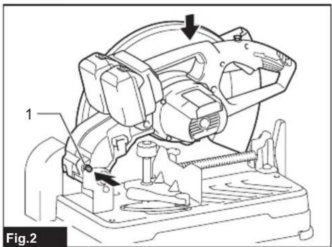
The tool head can be locked. Always lock the tool head when not in use or carrying.
To unlock, depress the tool head slightly and push the lock pin. To lock, return the lock pin while holding down the tool head.
▶ Fig.2: 1. Lock pin
Installing or removing battery cartridge
⚠️CAUTION: Always switch off the tool before installing or removing of the battery cartridge.
⚠️CAUTION: Hold the tool and the battery cartridge firmly when installing or removing battery cartridge. Failure to hold the tool and the battery cartridge firmly may cause them to slip off your hands and result in damage to the tool and battery cartridge and a personal injury.
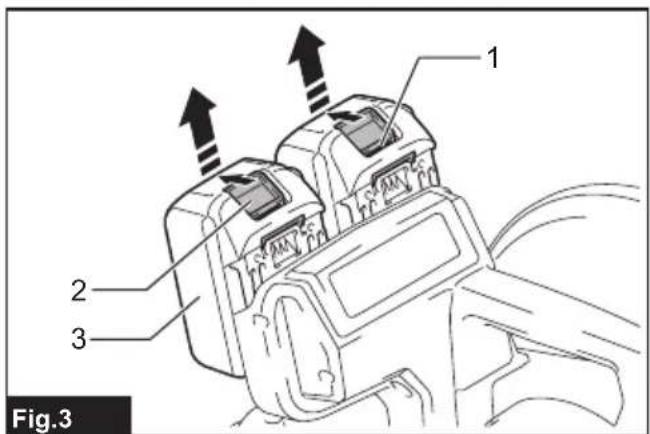
▶ Fig.3: 1. Red indicator 2. Button 3. Battery cartridge
To remove the battery cartridge, slide it from the tool while sliding the button on the front of the cartridge.
To install the battery cartridge, align the tongue on the battery cartridge with the groove in the housing and slip it into place. Insert it all the way until it locks in place with a little click. If you can see the red indicator on the upper side of the button, it is not locked completely.
⚠CAUTION: Always install the battery cartridge fully until the red indicator cannot be seen. If not, it may accidentally fall out of the tool, causing injury to you or someone around you.
⚠️CAUTION: Do not install the battery cartridge forcibly. If the cartridge does not slide in easily, it is not being inserted correctly.
NOTE: The tool does not work with only one battery cartridge.
Tool / battery protection system
The tool is equipped with a tool/battery protection system. This system automatically cuts off power to the motor to extend tool and battery life. The tool will automatically stop during operation if the tool or battery is placed under one of the following conditions.
Overload protection
When the tool is operated in a manner that causes it to draw an abnormally high current, the tool automatically stops. In this situation, turn the tool off and stop the application that caused the tool to become overloaded. Then turn the tool on to restart.
Overheat protection
When the tool is overheated, the tool stops automatically, and the battery indicator blink about 60 seconds. In this situation, let the tool cool down before turning the tool on again.

Overdischarge protection
When the battery capacity becomes low, the tool stops automatically and the battery indicator of the depleted battery cartridge will blink. If the product does not operate even when the switches are operated, remove the depleted battery cartridge from the tool and charge it.

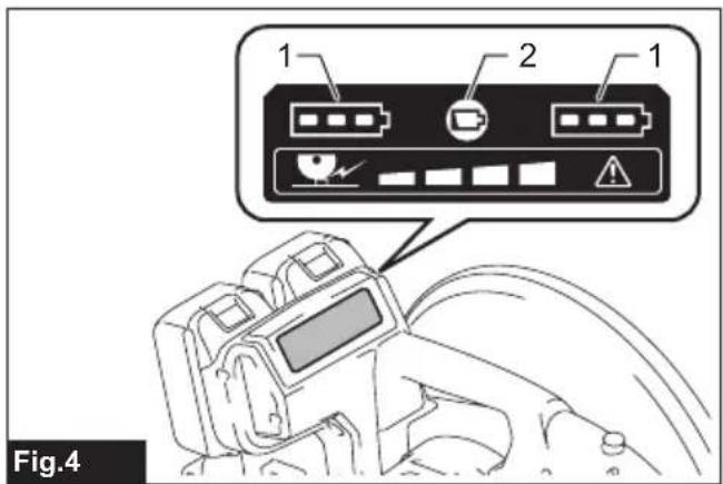
Indicating the remaining battery capacity
▶ Fig.4: 1. Battery indicator 2. Check button
Press the check button to indicate the remaining battery capacities. The battery indicators correspond to each battery.
| Battery indicator status Remaining | battery capacity | ||
| On Off | Blinking | ||
 | 50% to 100% | ||
 | 20% to 50% | ||
 | 0% to 20% | ||
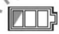 | Charge the battery | ||
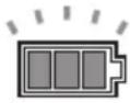
Indicating the remaining battery capacity
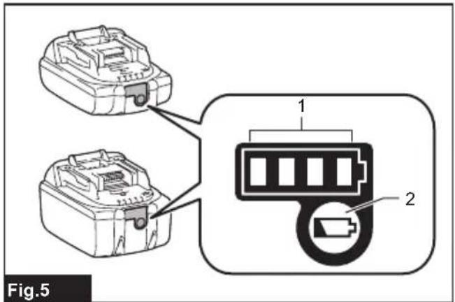
Only for battery cartridges with the indicator
Press the check button on the battery cartridge to indicate the remaining battery capacity. The indicator lamps
light up for a few seconds.
▶ Fig.5: 1. Indicator lamps 2. Check button
| Indicator lamps Remaining | capacity | ||
| Lighted Off | Blinking | ||
 | 75% to 100% | ||
 | 50% to 75% | ||
 | 25% to 50% | ||
 | 0% to 25% | ||
 | Charge the battery. | ||
 | The battery may have malfunctioned. | ||
NOTE: Depending on the conditions of use and the ambient temperature, the indication may differ slightly from the actual capacity.
NOTE: The first (far left) indicator lamp will blink when the battery protection system works.
Switch action
WARNING: Before installing the battery cartridge into the tool, always check to see that the switch trigger actuates properly and returns to the "OFF" position when released.
▶ Fig.6: 1. Lock-off button 2. Switch trigger
To prevent the switch trigger from being accidentally pulled, a lock-off button is provided. To start the tool, press the lock-off button and pull the switch trigger. Release the switch trigger to stop.
WARNING: NEVER defeat the lock-off button by taping down or some other means. A switch with a negated lock-off button may result in unintentional operation and serious personal injury.
WARNING: NEVER use the tool if it runs when you simply pull the switch trigger without pressing the lock-off button. A switch in need of repair may result in unintentional operation and serious personal injury. Return tool to a Makita service center for proper repairs BEFORE further usage.
NOTICE: Do not pull the switch trigger hard without pressing in the lock-off button. This can cause switch breakage.
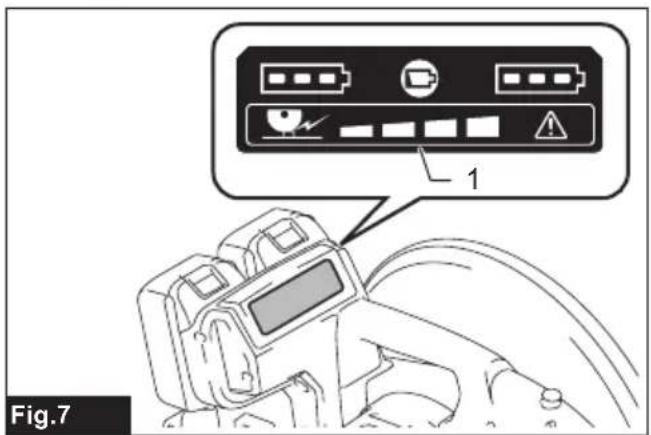
Load status indicator
The load status indicator shows the level of the load on the motor during cutting operation. As the load on the motor increases, the number of lighting lamp increases.
▶ Fig.7: 1. Load status indicator
Overload alert
If the motor is operated with excessive load, all lamps of the load status indicator will blink. In this case, reduce the load on the motor. If you continue to load the motor while the load status indicator is blinking, the tool will automatically stops in a few seconds due to overload protection.
NOTE: If an excessive load is generated at once, the tool automatically stops without blinking of the load status indicator.
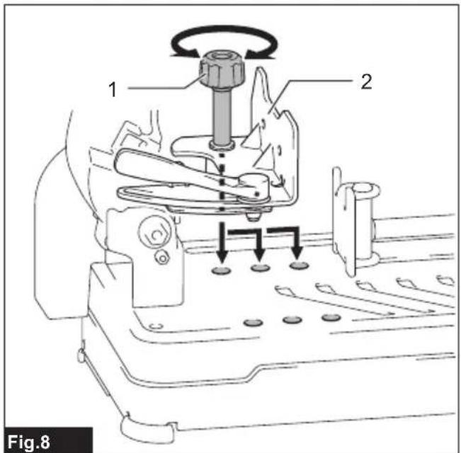
Interval between vise and guide plate
CAUTION: After adjusting the interval between the vise and the guide plate, make sure that the guide plate is properly secured. Insufficient fixing may result in personal injury.
The following interval settings of the vise are available:
• 0 - 170 mm (original setting)
- 35 - 205 mm
- 70 - 240 mm
If your work requires different setting, proceed as follows to change the spacing or interval.
Loosen the screw on the guide plate. Move the guide plate to the desired position then tighten the screw.
▶ Fig.8: 1. Screw 2. Guide plate
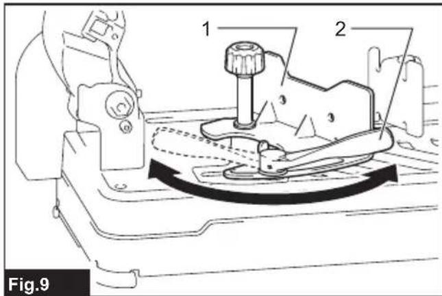
Cutting angle adjustment
CAUTION: After adjusting the angle of the guide plate, make sure that the guide plate is properly secured. Insufficient fixing may result in personal injury.
CAUTION: Do not operate the tool when the material is not firmly secured with the vise because of the cutting angle.
Turn the lever counterclockwise. Move the guide plate to the desired angle and fully tighten the lever.
▶ Fig.9: 1. Guide plate 2. Lever
NOTE: The scale on the guide plate is only a rough indication. For more accurate angle, use a protractor or triangle ruler. Keep the handle down so that the cut-off wheel extends into the base. At the same time, adjust the angle between the guide plate and the cut-off wheel with a protractor or triangle ruler.
Spark guard adjustment
Country specific
The spark guard is factory-installed with its lower edge contacting the base. Operating the tool in this position will cause many sparks to fly around. Loosen the screw and adjust the spark guard to a position at which minimum sparks will fly around.
▶ Fig.10: 1. Screw 2. Spark guard
Electronic function
The tools equipped with electronic function are easy to operate because of the following feature(s).
Soft start feature
Soft start because of suppressed starting shock.
ASSEMBLY
WARNING: Always be sure that the tool is switched off and the battery cartridge is removed before working on the tool. Failure to switch off and remove the battery cartridge may result in serious personal injury.
Opening center cap type safety guard
Country specific
For the tools equipped with center cap type safety guard, loosen the clamping screw first then raise the guard.
▶ Fig.11: 1. Clamping screw
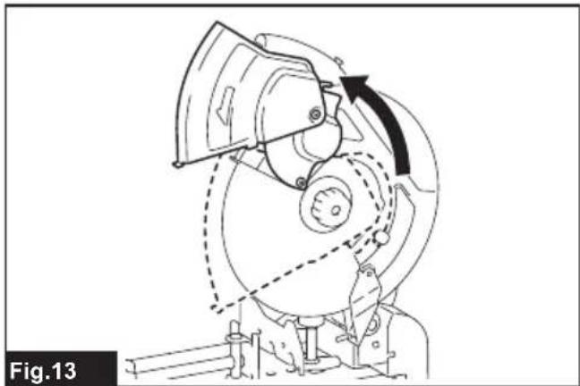
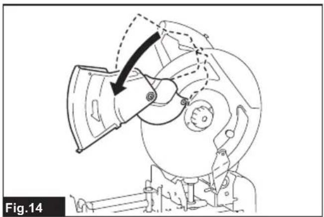
Opening European type safety guard
Country specific
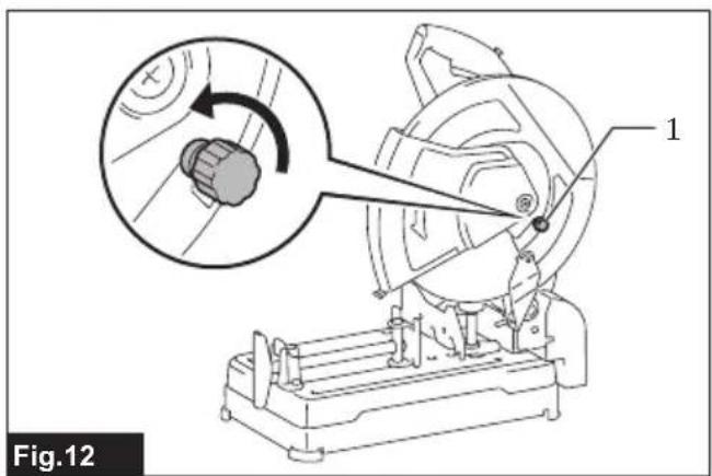
For the tools equipped with European type safety guard, loosen the clamping screw first then open the guard as shown.
▶ Fig.12: 1. Clamping screw
▶ Fig.13
▶ Fig.14
Removing or installing cut-off wheel
⚠️CAUTION: Be sure to tighten the toolless clamp securely. Insufficient tightening may result in severe injury.
⚠CAUTION: Always use only the proper inner and outer flanges which are provided with the tool.
A CAUTION: Always lower the safety guard after replacing the cut-off wheel.
⚠️CAUTION: Wear gloves when handling wheels.
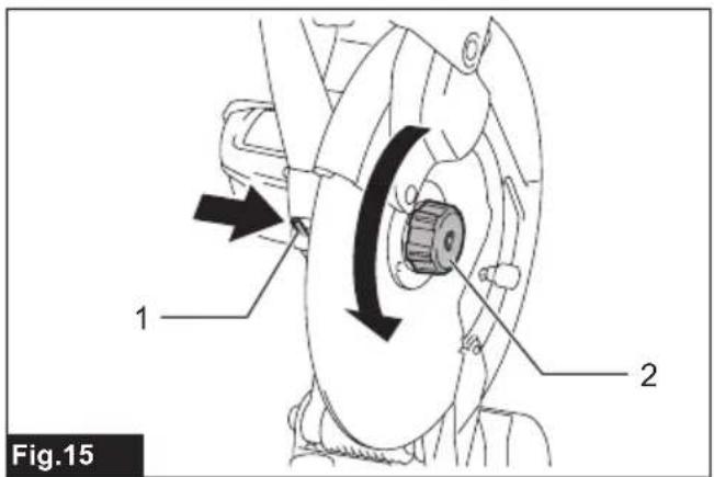
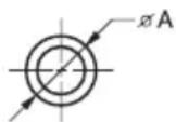
Raise the safety guard. Turn the toolless clamp counterclockwise while holding down the shaft lock. Then remove the toolless clamp, outer flange and cut-off wheel. When removing the cut-off wheel, do not remove the inner flange as well as the ring and O-ring.
▶ Fig.15: 1. Shaft lock 2. Toolless clamp
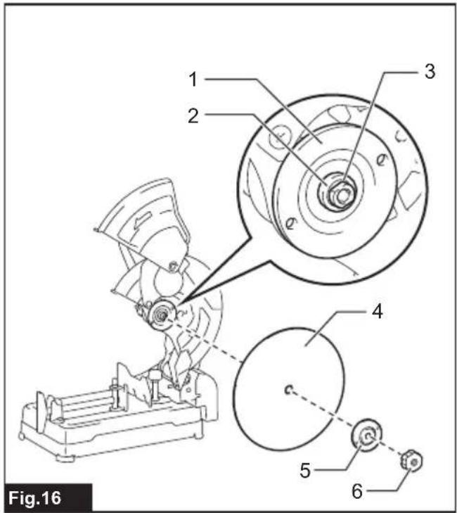
▶ Fig.16: 1. Inner flange 2. Ring 3. O-ring 4. Cut-off wheel 5. Outer flange 6. Toolless clamp
To install the cut-off wheel, follow the removal procedures in reverse. Make sure to fit the hole of cut-off
wheel to the ring and return the safety guard.
OPERATION
CAUTION: Proper handle pressure during cutting and maximum cutting efficiency can be determined by the amount of sparks that is produced while cutting. Do not force the cut by applying excessive pressure on the handle.
Reduced cutting efficiency, premature wheel wear, as well as, possible damage to the tool, cut-off wheel or workpiece may result.
Hold the handle firmly. Switch on the tool and wait until the cut-off wheel attains full speed before lowering gently into the cut. When the cut-off wheel contacts the workpiece, gradually bear down on the handle to perform the cut. When the cut is completed, switch off the tool and wait until the cut-off wheel has come to a complete stop before returning the handle to the fully elevated position.
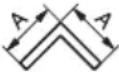
Cutting capacity
Maximum cutting capacity varies depending on the cutting angle and workpiece shape.
Max. cutting capacity with a brand-new cut-off wheel
| Cutting angle /Workpiece shape | 90° 45° | |
 | ø 127 mmø 127 mm | |
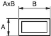 | 115 x 130 mm102 x 194 mm70 x 233 mm | 115 x 103 mm |
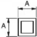 | 119 x 119 mm 106 x 106 mm | |
 | 137 x 137 mm 100 x 100 mm | |
NOTE: A workpiece thinner than 1.6 mm is recommended for cutting with this tool.
Securing workpiece
CAUTION: Always place the thread holder on the shaft threads when securing the workpiece.
Failure to do so may result in insufficient securing of the workpiece. This could cause the workpiece to be ejected or cause a dangerous breakage of the cut-off wheel.
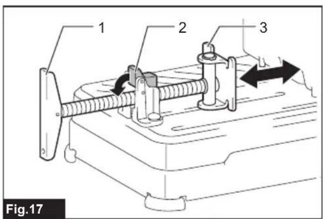
While the thread holder is lifted, the vise plate can be
moved in and out quickly. To grip a workpiece, push the handle until the vise plate contacts the workpiece then return the thread holder. Turn the handle clockwise until the workpiece is securely retained.
▶ Fig.17: 1. Handle 2. Thread holder 3. Vise plate
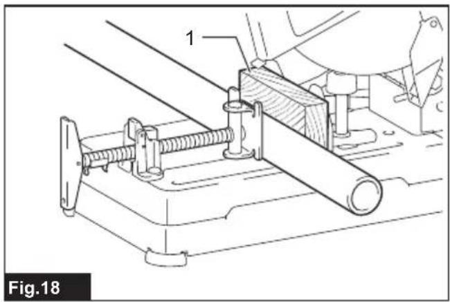
When the cut-off wheel has worn down considerably, place a spacer block behind the workpiece as shown in the figure. You can more efficiently utilize the worn wheel by using the mid point on the periphery of the wheel to cut the workpiece. Use a sturdy and non-flammable material for a spacer block.
▶ Fig.18: 1. Spacer block
When cutting workpieces over 85 mm wide at an angle, attach a straight piece of wood (spacer) over 190 mm long x 40 mm wide to the guide plate as shown in the figure. Attach this spacer with screws through the holes in the guide plate. Make sure that the cut-off wheel does not contact the spacer when the tool head is depressed.
▶ Fig.19: 1. Guide plate 2. Spacer block (over 190 mm long x40 mm wide) 3. Workpiece (over 85 mm wide) 4. Vise plate
NOTICE: When using a spacer block, install the guide plate to the position nearest to the neck of the tool head.
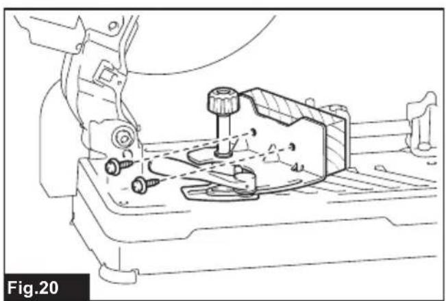
▶ Fig.20
When the cut-off wheel has worn down, raise the cutting position by putting a spacer block which is slightly narrower than the workpiece as shown in the figure. This will help you to utilize the cut-off wheel economically.
▶ Fig.21: 1. Vise plate 2. Workpiece diameter 3. Guide plate 4. Spacer block width
Long workpieces must be supported by blocks on either side so that it will be level with the base top. Use non-flammable material for supporting blocks.
▶ Fig.22: 1. Supporting block
Before carrying, remove the batteries and fold down the tool head, and then lock it. Hold the handle when carrying.
▶ Fig.23
CAUTION: Always be sure that the tool is switched off and the battery cartridge is removed before attempting to perform inspection or maintenance.
NOTICE: Never use gasoline, benzine, thinner, alcohol or the like. Discoloration, deformation or cracks may result.
To maintain product SAFETY and RELIABILITY, repairs, any other maintenance or adjustment should be performed by Makita Authorized or Factory Service Centers, always using Makita replacement parts.
CAUTION: These accessories or attachments are recommended for use with your Makita tool specified in this manual. The use of any other accessories or attachments might present a risk of injury to persons. Only use accessory or attachment for its stated purpose.
If you need any assistance for more details regarding these accessories, ask your local Makita Service Center.
• Abrasive cut-off wheels
• Makita genuine battery and charger
NOTE: Some items in the list may be included in the tool package as standard accessories. They may differ from country to country.
SPÉCIFICATIONS
▶ Fig.9: 1. Plaque de guidage 2. Levier
▶ Abb.18: 1. Distanzblock
VEILIGHEIDSWAAR- SCHUWINGEN
▶ Fig.11: 1. Klemschroef
▶ Fig.22: 1. Steunblok
OPTIONELE ACCESSOIRES
- Intended use
- Noise
- Vibration
- Declarations of Conformity
- For European countries only
- For the UK
- SAFETY WARNINGS
- General power tool safety warnings
- Save all warnings and instructions for future reference.
- Cut-off machine safety warnings
- Kickback and related warnings
- Additional safety warnings
- SAVE THESE INSTRUCTIONS.
- Important safety instructions for battery cartridge
- Tips for maintaining maximum battery life
- INSTALLATION
- Securing the base
- FUNCTIONAL DESCRIPTION
- Unlocking/locking tool head
- Installing or removing battery cartridge
- Tool / battery protection system
- Overload protection
- Overheat protection
- Overdischarge protection
- Indicating the remaining battery capacity
- Switch action
- Load status indicator
- Overload alert
- Interval between vise and guide plate
- Cutting angle adjustment
- Spark guard adjustment
- Country specific
- Electronic function
- Soft start feature
- ASSEMBLY
- Opening center cap type safety guard
- Opening European type safety guard
- Removing or installing cut-off wheel
- OPERATION
- Cutting capacity
- Securing workpiece
- VEILIGHEIDSWAAR- SCHUWINGEN
- OPTIONELE ACCESSOIRES
Brand : MAKITA
Model : DLW140
Category : Garden shredder