USER MANUAL EB 1000 B MTD


Enter all the information shown on the identification plate of your lawn scarifier into the box below. The identification plate is located next to the engine. This information is very important for identifying any spare parts that are to be ordered at a later date, and for customer service.
Reportez dans l'encadré ci-dessous toutes les indications figurant sur la plaquette signalétique qui se trouve à proximité du moteur de l'appareil. Les indications qu'elle contient sont d'une importance capitale car elles permettront plus tard de déterminer les pièces de rechange et d'accomplir les prestations de service après-vente.
Tragen Sie alle Angaben auf dem Typenschild Ihres Gerätes in das nachfolgende Feld ein. Sie finden das Typenschild in der Nähe des Motors. Diese Angaben sind sehr wichtig für die spätere Identifikation zur Bestellung von Geräte-Ersatzteilen und für den Kundendienst.
Riportate tutti i dati della targhetta delle caratteristiche del Vostro apparecchio nello specchietto sottostante. La targhetta delle caratteristiche si trova vicino al motore. Questi dati sono importantissimi per la successiva identificazione, per l'ordinazione di ricambi della macchina e per il servizio assistenza.
Registe todos os dados indicados na placa de característica do seu aparelho no quadro seguinte. A placa de características encontra-se perto do motor. Estes dados são muito importantes para a identificação posterior das peças de reposição ao fazer encomendas e para os serviços de assistência técnica.
Apunte en el cuadro siguiente todos los datos contenidos en la placa de características de su aparato. La placa de características se encuentra en las cercanías del motor. Estos datos son muy importantes para la posterior identificación en el pedido de piezas de repuestos del aparato y para el Servicio de Postventa.
Notér alle angivelser fra typeskiltet på Deres vertikalskærer i nedenstående kasse. Typeskiltet på vertikalskæreren findes i nærheden af motoren. Disse angivelser er meget vigtige for kundetjenesten og for på et senere tidspunkt at kunne identificere vertikalskærerens reservedele.
Vul alle gegevens van het typeplaatje van uw machine in het onderstaande vakje in. U vindt het typeplaatje in de buurt van de motor. Deze gegevens zijn zeer belangrijk voor de klantenservice en om later te kunnen vaststellen welke vervangingsonderdelen voor de machine nodig zijn.
Anteckna alla uppgifter från typskylten i fältet här nedan. Typskylten hittar i närheten av motorn. Uppgifterna från typskylten behövs om du ska beställa reservdelar eller när du kontaktar en serviceverkstad.
Skriv opp alle angivelsene som er oppført på maskinens typeskilt i feltet nedenfor. Du finner typeskiltet i nærheten av motoren. Disse informasjonene er svært viktige for senere identifikasjon for bestilling av reservedeler og for kundeservice.
Merkitse alla olevaan ruutuun tyyppikilven kaikki tiedot. Tyyppikilpi sijaitsee moottorin läheisyydessä. Siinä olevat tiedot ovat hyvin tärkeitä, kun tilaat varaosia tai tarvitset huoltomiehen apua.
Εγγράψτε όλα τα στοιχεία στην πινακίδα του μηχανήματός σας στο πλαίσιο που ακολουθεί. Θα βρείτε την πινακίδα του μηχανήματος κοντά στον κινητήρα. Αυτά τα στοιχεία έχουν μεγάλη σημασία για την μετέπειτα αναγνώριση για την παραγγελία ανταλλακτικών του μηχανήματος και για την υπηρεσία εξυπηρέτησης πελατών.
GB
F
D
|
P
E
DK
NL
S
N
SF
GR
| ENGLISH | 1 |
| FRANÇAIS | 5 |
| DEUTSCH | 9 |
| ITALIANO | 13 |
| PORTUGUÊS | 17 |
| ESPAÑOL | 21 |
| DANSK | 25 |
| NEDERLANDS | 29 |
| SVENSKA | 33 |
| NORSK | 37 |
| SUOMI | 41 |
| ΕΛΛΕΗΝΙΚΑ | 45 |
|
| . . . . . . . . . . . . . . . . . . . . . . . . . . . . . . . . . . . . . . . . . . . . . . . . . . . . . . . . . . . . . . . . . . . . . . . . . . . . . . . . . . . . . . . . . . . . . . . . . . . . . |
| . . . . . . . . . . . . . . . . . . . . . . . . . . . . . . . . . . . . . . . . . . . . . . . . . . . . . . . . . . . . . . . . . . . . . . . . . . . . . . . . . . . . . . . . . . . . . . . . |
| . 0. . . . . . . . . . . . . . . . . . . . . . . . . . . . . . . . . . . . . . . . . . . . . . . . . . . . . . . . . . . . . . . . . . . . . . . . . . . . . . . . . . . . . . . . . . . . . . . . . . . |
TABLE OF CONTENTS
This unit is intended exclusively:
■for use in accordance with the descriptions and safety instructions specified in this operating manual,
■for use in the garden,
■for mowing lawn edges and small or in-accessible grassy areas (e.g. under bushes).
■ as well as for cutting rank weeds, shrubs and undergrowth.
This unit is not permitted for any other use. The user is liable for any injury to third parties or damage to their property.
Operate the unit only in the delivered technical condition as stipulated by the manufacturer.
Any unauthorised changes to the unit will exempt the manufacturer from liability for any resulting damage.
2. SAFETY WARNINGS
- Read the instructions carefully. Be familiar with the controls and proper use of the unit.
Children and adolescents (<16 years old) must not manipulate unit, except for adolescents in training and under the supervision of a specialist.
- Keep all bystanders at least 5 m away from the unit during operation.
■Make sure there are no branches or stones etc. in the way of the cord or the cutting blade, before starting up the appliance.
■Use the unit only in daylight or good artificial light.
■Be aware of the risk of injury ta the head, hands and feet.
■When working with the unit, always wear sturdy, rubber-soled footwear and body protection appropriate to operation of the unit.
■When working with the unit, use the safety attachments supplied.
■Before starting, adjust the handle to your size.
■Do not overreach. Keep proper footing and balance at all times.
■ All interventions, whether for maintenance, repair or for changing cutting head or safety attachments, must be undertaken with the motor stopped.
■Frequently inspect the condition of the cutting head, All damaged parts must immediately be replaced.
■Follow all the required precautions when undertaking replacement.
■Use only replacement parts recommended by the manufacturer.
■ All guards must be installed properly before operating the unit.
■Caution-Danger! Cutting head is still running.
- Keep unit clean of vegetation and other materials.
- Keep connecting wires away from the tools.
■ Turn off the unit and pull the main plug before set-up or cleaning of the unit, and before testing for tangled or damaged wires.
■The connecting wires must be inspected regularly for signs of damage or age.
■The unit must not be used if the connecting wires are not in perfect condition.
■Maintenance/servicing and cleaning of
| MINIMUM WIRE SIZE FOR EXTENSION CORDS FOR 230V APPLIANCES USING 0-6 AMPS |
| Cord length (m) 7 | 15 30 45 | | | |
| Wire size ( mm2 ) | 1,2 1,6 1,6 2,0 | | | |
| | | | | | | |
| Attention!Observe the following safety warnings. | Read operator's manual. | Wear head, eye and ear protection. | Keep bystanders at least 15 m away from unit during operation. | If the electric cord is damaged remove plug from socket and replace it. | Do not operate unit in rain. | Ignition/ Power Switch On/ Start/Run | Ignition/ Power Switch off or stop. |
the unit or adjustments to cutting height or work height may only be performed when the motor is off/still and the main plug is disconnected.
■ Cord Sets - Make sure your cord set is in good condition. When using a cord set, be sure to use a cord that is heavy enough to carry the current that your unit will draw. An undersized cord set will cause a drop in line voltage resulting in power and overheating.
The table (below) shows the correct size to use depending on the cord length and nameplate amperage rating. If in doubt, use the next heavier size line gauge. The smaller the gauge number, the heavier the cord.
For safety reasons, the socket used to power the unit should be backed up by a residual current-operated (FI) circuitbreaker which can be tripped by a max. current of 30mA.
A fatal injury could occur if you sever the mains cable while mowing is taking place. Slowly step away from the unit. Pull the plug out of the mains socket.
3. ASSEMBLY INSTRUCTIONS
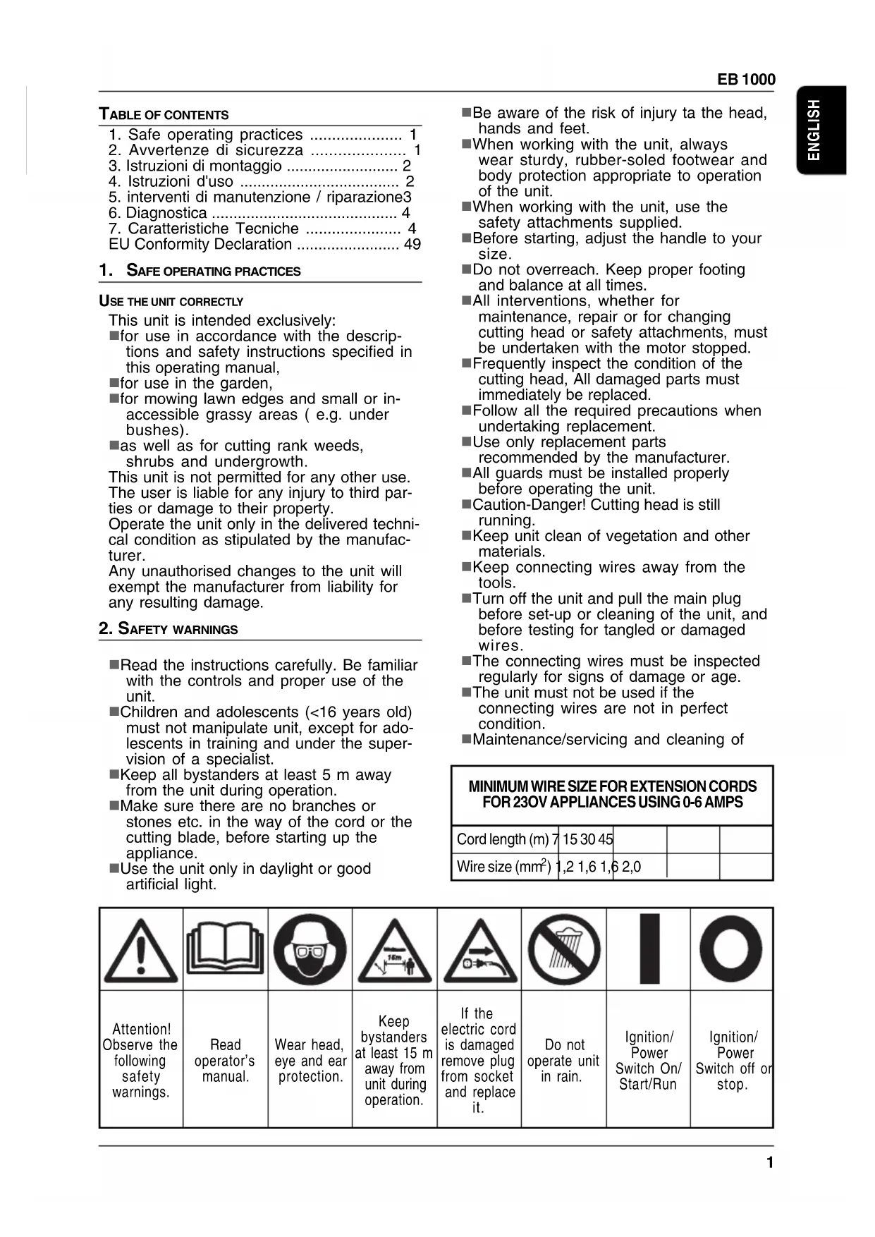
HANDLE
■Push the handle down onto the boom ( Fig. 1).
■ Install and tighten the bolts and nuts.
SAFETY GUARD ASSEMBLY
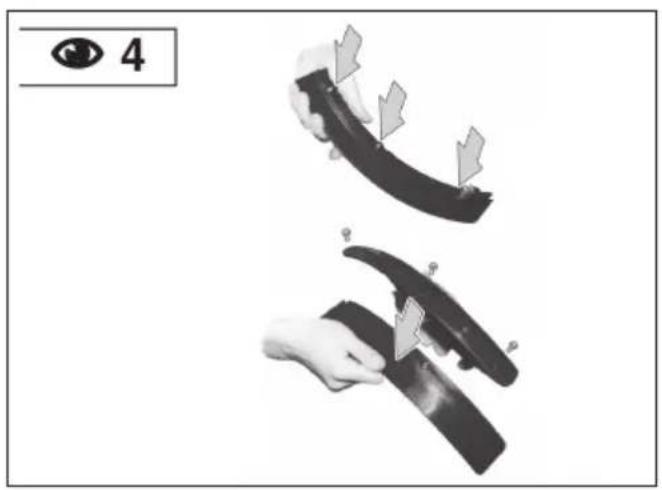
■Assemble the safety guard as shown in FIG. 4.
■Assemble the cutting cord blade as shown in Fig. 4.
STRING GUARD
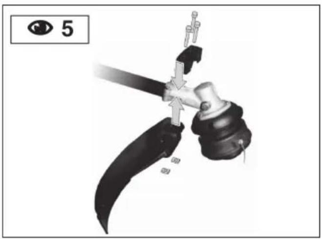
■ Place the safety guard onto the coupling joint pointing towards the motor as indicated in FIG. 5.
■ Fix the safety guard into position with the special lock FIG. 5.
■ Use the screw indicated in FIG. 5 to prevent the safety guard from rotating.
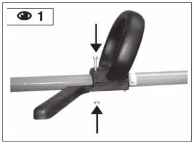
CUTTING BLADE ASSEMBLY
■ Follow indications given in FIG. 2 to assemble the cutting blade.
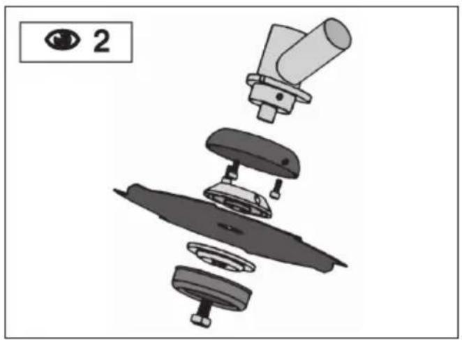
ASSEMBLY OF REEL WITH NYLON CORD
■ Proceed as indicated in FIG. 3 to assemble the reel with nylon cord.
NOTE: To make installing or removing the add-on easier, place the unit on the ground or on a work bench.
Removing the Cutting Attachment or Add-Ons:
■Turn the knob counterclockwise to loosen ( ① FIG. 19).
■Press and hold the release button ( Fig. 19).
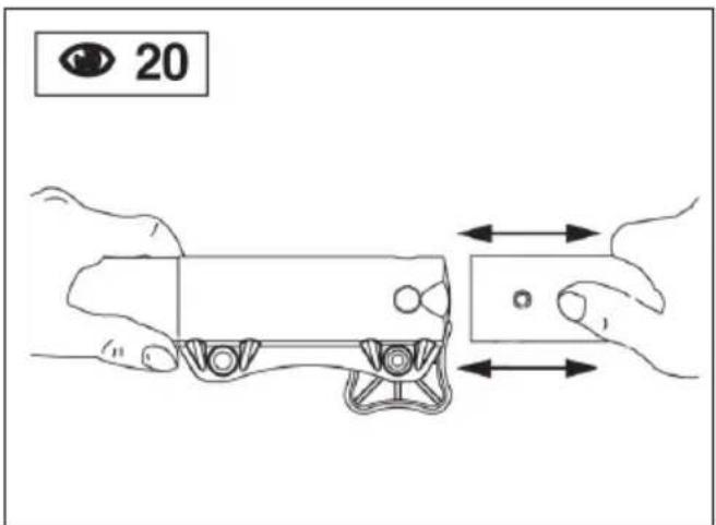
■While firmly holding the upper shaft tube, pull the cutting attachment or add-on straight out of the Click-Link ® coupler ( Fig. 20).
Installing the Cutting Attachment or Add-Ons:
■Turn knob counterclockwise to loosen ( Fig. 19).
■While firmly holding the add-on, push it straight into the Click-Link ® coupler ( Fig. 20).
NOTE: Aligning the release button with the guide recess will help installation ( Ⓞ FIG. 20).
■FOR BASIC TRIMMING OR FOR MOST ADD-ONS - Locate and lock the release button into the Primary hole ( Fig. 20).
■Turn the knob clockwise to tighten ( Fig. 21). Ensure it is tight before operating the unit.
4. OPERATING INSTRUCTIONS
CONNECTING THE CORD
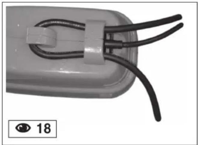
To prevent disconnection when you connect the extension cord to the power cord, use the cord hook (Fig. 18), or tie the cords in a knot.
STARTING / STOPPING
■Press control switch to switch on the appliance, release to switch off.
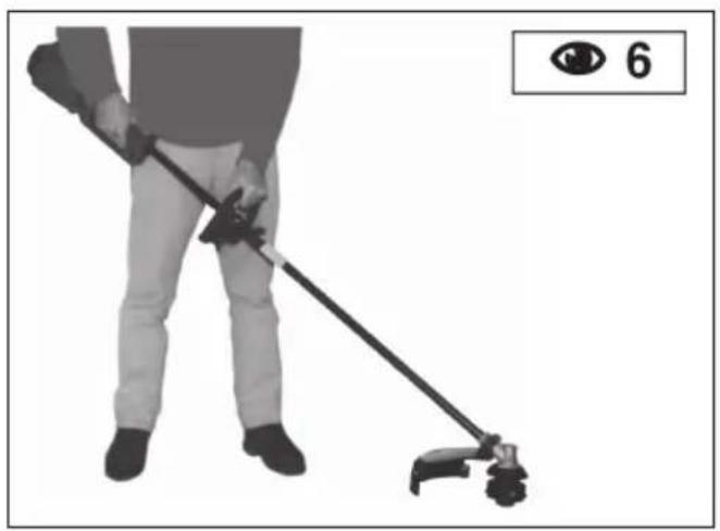
HOLDING THE TRIMMER
■ Hold the trimmer as shown FIG. 6
ADJUSTING LINE LENGTH
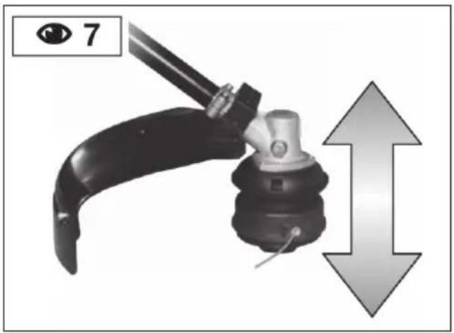
The trimmer has a bump (cutting) head, which releases more trimming line without stopping the motor.
■When the cord starts to get a bit short, knock the cutting head on the bare ground or on hard ground to make the appliance work at top speed. Repeat the process as often as necessary ( Fig. 7).
DECORATIVE TRIMMING
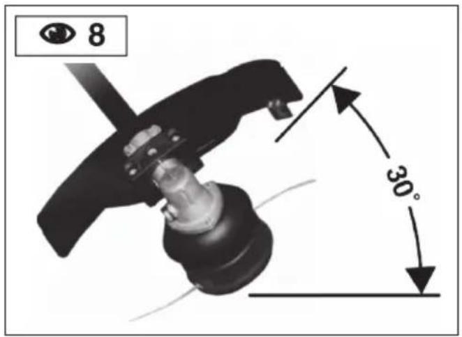
Use a 30-degree angle to remove all vegetation around trees, posts, fences (Fig. 8).
EDGING
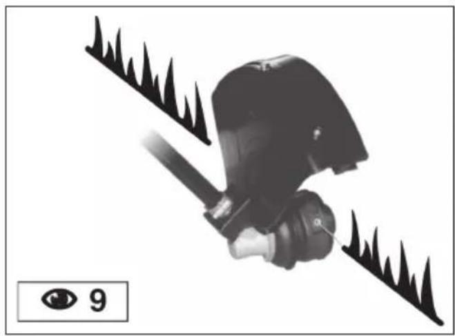
When edging, let the tip of the trimming line do the work ( Fig. 9)
TRIMMING TIPS
( Ⓞ Fig. 9)
- The cutting head will be at the correct angle by holding it parallel to the ground.
- DO NOT FORCE THE UNIT.
- Cut to your left for best cutting, and to
throw the clippings away from the operator.
-
Move the trimmer slowly in and out of the area being cut, using a forward-backward or side-to-side motion. Maintain top speed for best cutting.
-
Trim only when grass and weeds are dry.
-
The life of your cutting line depends on your trimming techniques, what is being cut, and where the cutting is being done. Some line breakage will occur from:
■Entanglement with foreign matter
■Normal line fatigue
■Attempting to cut thick weeds
■Forcing the line into walls or fenceposts
5. MAINTENANCE AND REPAIR INSTRUCTIONS
INSTALLING A NEW TRIMMING LINE
The trimming line may be replaced by two methods - rewinding the existing reel or installing a prewound reel.
REWINDING THE EXISTING REEL
To rewind the existing reel you must:
■Check for the correct line size.
■Remove the inner reel and spring.
■Wind the reel with the new line.
■Reinstall the existing reel and spring.
THE CORRECT LINE TO USE
Use a dual line reel with ∅ 2,00 mm.
REMOVING THE EXISTING REEL
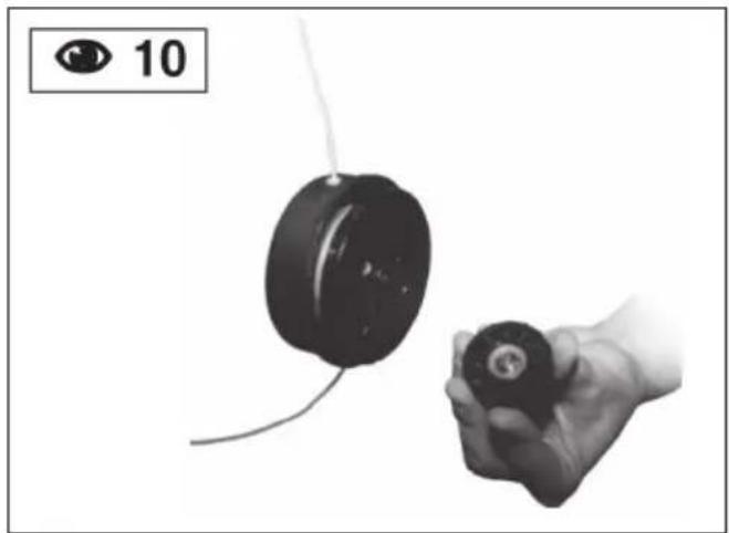
■Unscrew the coil lock-nut clockwise ( Fig. 10).
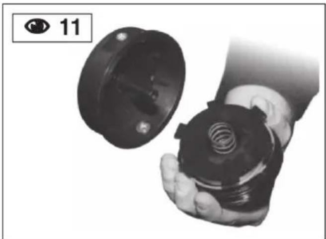
■Remove the inner reel ( ◎ Fig. 11).
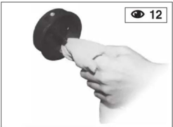
■Use a clean cloth to clean the inside of the outer spool ( Fig. 12).
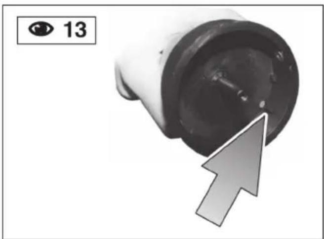
■Check the indexing teeth on the reel and spool for wear ( Fig. 13). If necessary, replace the reel and spool.
WINDING THE EXISTING REEL
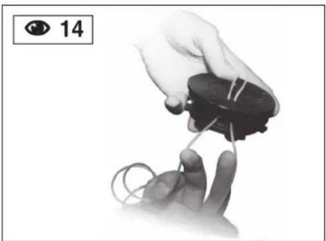
■Insert the ends of new trimming line into the inner reel holes (⑨ FIG. 14).
■ Loop the line into two equal lengths before inserting it into the holes.
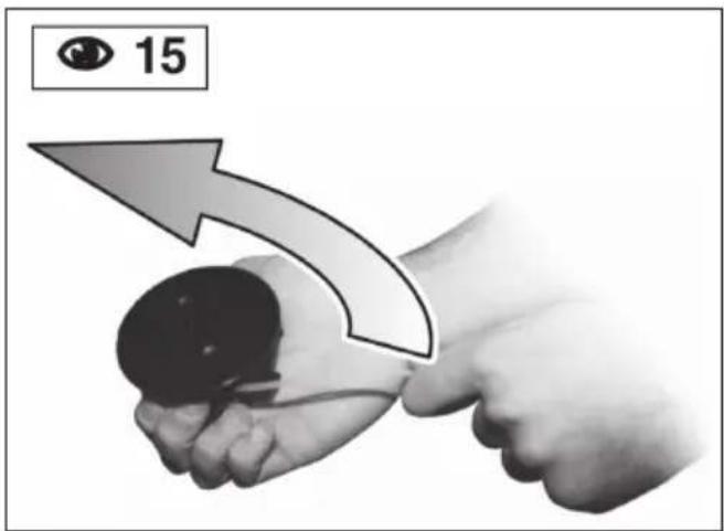
■Wind the line, in even and tight layers ( Fig. 15), onto the reel, and in the direction indicated.
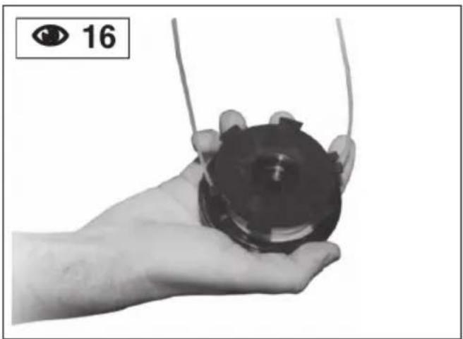
■Push the ends of the line into the slots( Ⓞ Fig. 16).
REINSTALLING THE REEL
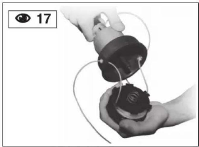
■Insert the ends of the line through the eyelets in the outer spool ( Fig. 17).
- Grasp the ends and pull firmly to release the line from the slots in the spool.
■Screw up the coil lock-nut again anticlockwise( Ⓞ Fig. 10).
Line installation is now complete.
INSTALLING A PREWOUND REEL
■Use the same instructions as the existing reel:
■The Correct Line to Use;
■Removing the Existing Reel;
■Reinstalling the Reel.
CLEANING / STORAGE
■Do not block the air vents.
■ Do not use strong detergents on the plastic housing or handle.
■Moisture can cause a shock hazard. Wipe off moisture with a soft cloth.
■Clean the unit thoroughly before storing. Hang the unit by the handle loop and store it in a dry, well-ventilated area, out of the reach of children.
Electric appliances must only be repaired by qualified technicians.
- TROUBLESHOOTING
| PROBLEM | CAUSE | ACTION |
| ■Motor will not start | 1. Motor stops / will not start2. Cutting head bound with grass or debris | 1. Check curd to see if it is plugged into an electrical outlet2. Stop motor and clean cutting head |
| ■Cutting head will not turn when throttle is squeezed | 1. Flex shaft broken2. Flex shaft not engaged | 1. Contact service dealer2. Contact service dealer |
| ■Cutting head will not advance line | 1. Cutting head out of line2. Inner reel bound up3. Cutting head dirty4. Indexing teeth worn or burred5. Line welded6. Line twisted when re-filled7. Nut enough line is exposed | 1. Refill with new cutting line2. Replace inner reel3. Clean inner reel and outer spool4. Replace inner reel and outer spool5. Disassemble, remove the welded section and rewind the line6. Disassemble and rewind reel7. Push the Bump Knob and pull out 102 mm of line until the line is outside of the cutting head |
- SPECIFICATIONS
| MOTOR |
| Motor | Electric |
| Operating RPM | 7500 - 8500 g/m |
| Ignition Switch | Control switch |
| Drive shaft | 6,2 mm |
| Cutting head | "Bump Head" reel feeding |
| Vibration Level | 3,65 m/s 2 |
| Sound pressure level (no load) | LPAm = 74,8 dB (A |
| Measured sound power level (no load) | LWA = 94,8 dB (A |
| Guaranteed sound power level (no load) | LWA = 96 dB (A |
| Cutting path diameter | 400 mm |
| Operating weight | 5,5 Kg |
| Trimming line diameter | 2,0 mm |
All information, illustrations and specifications in this manual are based on the latest product information available at the time of printing, We reserve the right to make changes at any time without notice.
SOMMAIRE
5. UNDERHÅLLS- OCH REPARATIONSFÖRESKRIFTER
MONTERING AV NY SKÄRTRÅD
SETTE INN NY KLIPPETRÅD
a) 41xC175Gxxx
b) 41xC125Cxxx
c) 41xC100Cxxx
41
BJ Label here (Model number typ of unit brand name)
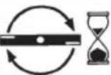 | a) 7500 1/minb) 8000 1/minc) 8000 1/min |  | a) 700 Wb) 1000 Wc) 1000 W | 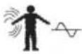 | aw = 3,6 m/sec2 |
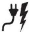 | ~230 V, 50 Hz | 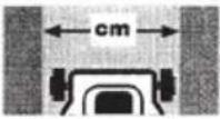 | a) 37 cmb) 37 cmc) 23/42 cm | | LwA: 95 / 96 dB (A) |
 | a) 4,9 Kgb) 5,5 Kgc) 5,5 Kg | 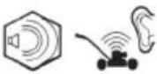 | NOVICON S.a.s.di R. Castelli&C.Via dellaFontana I 23804Monte Marenzo(LC) | 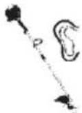 | LpA = 84 dB (A) |
| GB-The demands of EU standards and rules listed below are fulfilled:F-Les revendications des normes suivantes et les directives par l'Union Européenne sont executées:D-Die Forderungen folgender Normen und Richtlinien der EWG sind erfüllt:I-Tutte le Normative CEE qui di seguito elencate saranno rispettate:NL-De machine beantwoordt volledig aan de Europese normen:E-Las exigenicias de las Normas y Reglas CEE siguientes serán cumplidas:SLO – Izpolnjene so naslednje direktive in standardi Evropske skupnosti: | P-As Exigências das Normas e Directivas Seguintes do C. E. são realizados:GR-Oı απατησεις πληρουν τους κανόνες και τις κατευθυνσεις της Ευρωπαικης Οικονομικης Κοινότητας:DK-De ovenstående Normer og Standarder for EU er opfyldt:N-Alle Krav i Henhold til EU Direktivet listet nedenfor er oppfylt:S-Denna Maskin uppfyller nedan angivna EU Regler:FIN-Alla luetellut EY:n standardit ja vaatimukset täytetään:H – Az alábbi előirasoknak és szabványoknak megfelel: |
| 89/ 336EWG – 92/ 31EWG | 73/23EC // 98/ 37EG | 2000/ 14 EC |
| EN ISO 14982 | | | |
MTD Products Aktiengesellschaft
Industriestraße 23
D-66129 Saarbrücken
Tel.: ++49 6805 79-0 / Fax: ++49 6805 79 442
MTD Products Aktiengesellschaft
Industriestraße 23
D-66129 Saarbrücken
Germany
MTD International France
B.P. 453 Saint-Etienne du Rouvray
76806 Cedex

02 32 91 94 32

02 32 91 94 36
SV
OX6 OUR Bicester, Oxfordshire

0 18 69 36 36 36

0 18 69 36 36 20
CH
MTD Schweiz AG
Allmendstraße 14
5612 Villmergen

05 66 18 46 00

05 66 18 46 09
PL
MTD Poland sp. z o.o.
UL. Ogrodnicza 1
84-252 Orle

058 57 20 701

058 57 20 699
RUS