Smart BM8735 - Lawn mower MTD - Free user manual and instructions
Find the device manual for free Smart BM8735 MTD in PDF.
Frequently Asked Questions - Smart BM8735 MTD
User questions about Smart BM8735 MTD
0 question about this device. Answer the ones you know or ask your own.
Ask a new question about this device
Download the instructions for your Lawn mower in PDF format for free! Find your manual Smart BM8735 - MTD and take your electronic device back in hand. On this page are published all the documents necessary for the use of your device. Smart BM8735 by MTD.
USER MANUAL Smart BM8735 MTD
natural_image
Line drawing of a manual lawn mower with levers and blades (no text or symbols)

text_image
D GB I F SLO HR LT
B11
FORM NO. 769-01111A
MTD Products Aktiengesellschaft • Saarbrücken • Germany
1
natural_image
Technical line drawing of a lawn mower with attached turbine blade (no text or symbols)2
text_image
1 3 7 5 6 A 4 B 245
natural_image
Simple line drawing of a mechanical device with an arrow indicating direction (no text or symbols)RIGHT TO CORRECT CORRECT CORRECTO
natural_image
Simple line drawing of a mechanical or electrical component with a lever and spring (no text or symbols)RIGHTING CORRECT CORRECT CORRECTO
natural_image
Simple line drawing of a mechanical clamp or lever assembly (no text or symbols)FALSCH WRONG INCORRECT INCORRECTO
text_image
Technical diagram of a mechanical tool with numbered parts labeled 1 through 5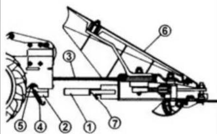
text_image
Technical diagram of a mechanical device with numbered components for identification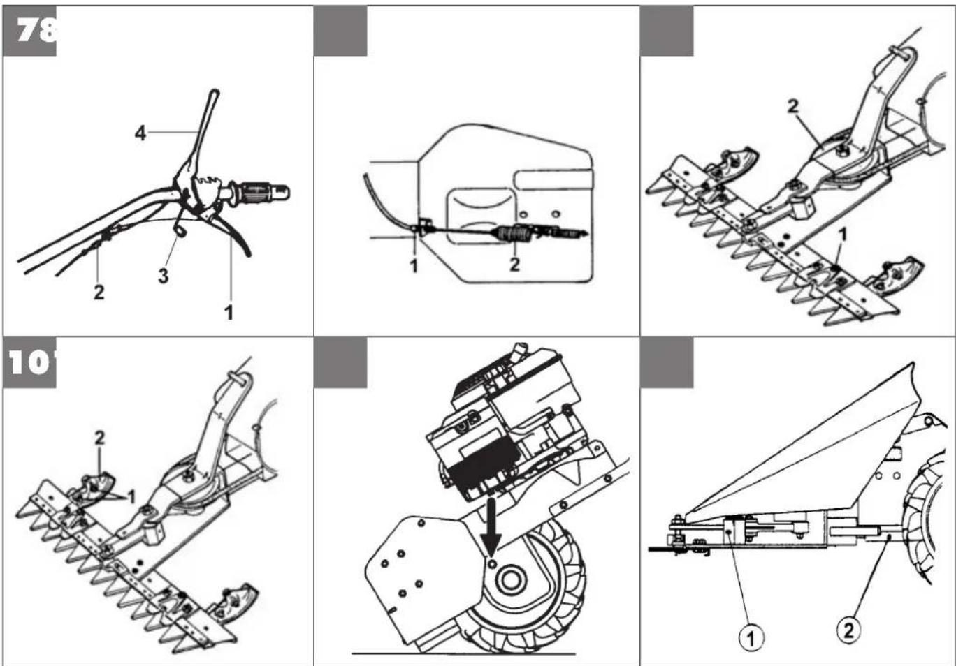

Read the instructions manual before operating on the machine.
text_image
Warning symbol with exclamation mark and hand holding a knife, commonly used in safety or hazard prevention contextsKeep hands and feet away from the blades!
Instructions for operating
Assembly
Regulating
Maintenance
Technical Details
Noise
Fault
Serious risk for operator and bystander safety.
Translation of original user instructions
Introduction
Dear Customer:
Thank you for your confidence in purchasing our products. We wish you to enjoy using our machines.
The following working instructions have been issued to ensure you a reliable running from the beginning. If you carefully follow such information the machine will operate with complete satisfaction have a long service life.
Our machines are tested under the most severe conditions before being put into production and are subjected to strict continuous tests during manufacturing stages.
The present unit has been tested in the country of origin by independent testing authorities in accordance with strict work norms and safety standards.
When required, only original spare parts must be used to maintain guaranteed function and safety levels.
The operator forfeits any claims which may arise, if the machine shows to be fitted with components other than original spare parts.
Subject to changes in design and construction without notice.
For any questions or further information and spare part orders, we need to be informed of the unit serial number printed on the side of the machine.
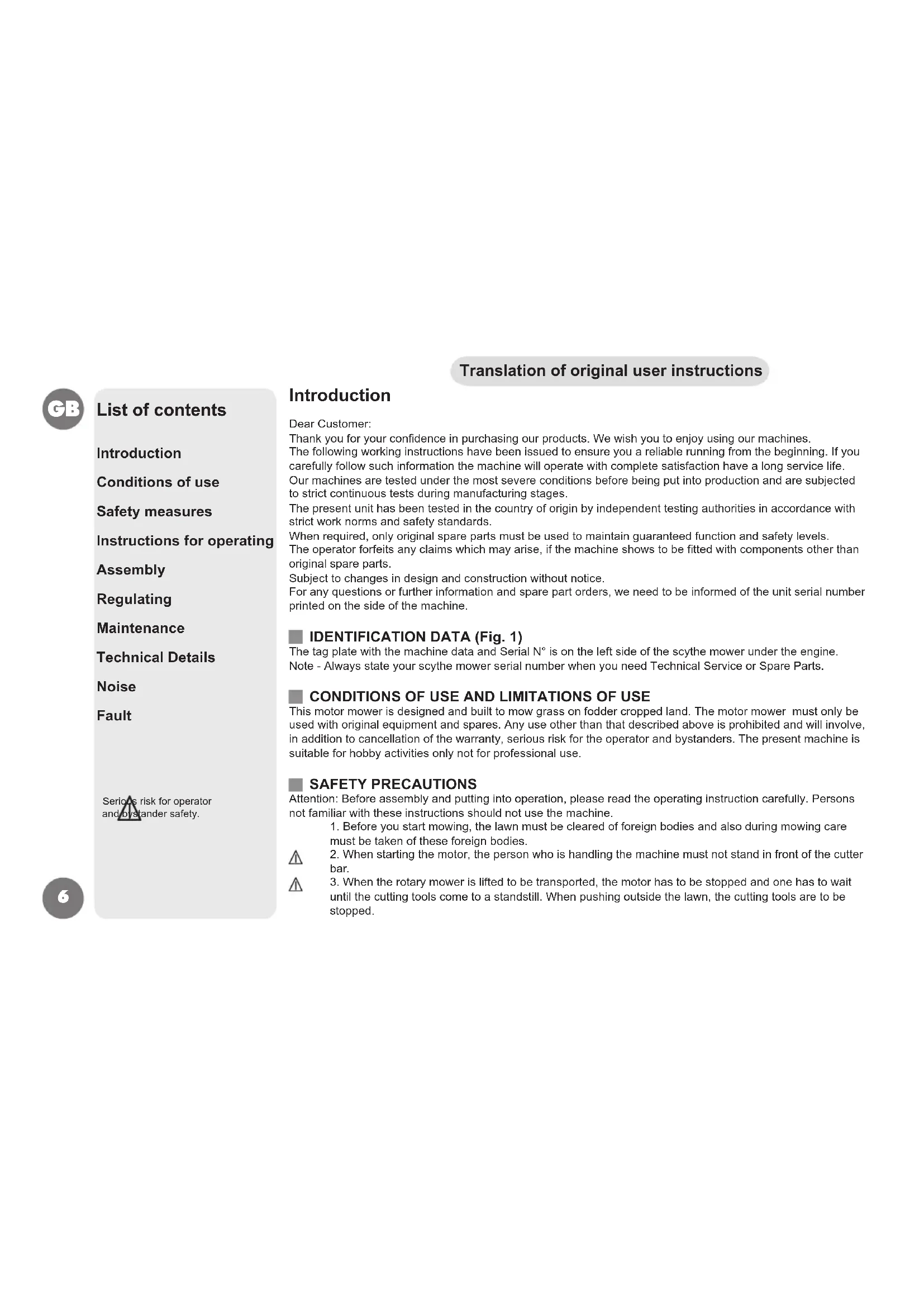
IDENTIFICATION DATA (Fig. 1)
The tag plate with the machine data and Serial N° is on the left side of the scythe mower under the engine.
Note - Always state your scythe mower serial number when you need Technical Service or Spare Parts.
CONDITIONS OF USE AND LIMITATIONS OF USE
This motor mower is designed and built to mow grass on fodder cropped land. The motor mower must only be used with original equipment and spares. Any use other than that described above is prohibited and will involve, in addition to cancellation of the warranty, serious risk for the operator and bystanders. The present machine is suitable for hobby activities only not for professional use.
SAFETY PRECAUTIONS
Attention: Before assembly and putting into operation, please read the operating instruction carefully. Persons not familiar with these instructions should not use the machine.
- Before you start mowing, the lawn must be cleared of foreign bodies and also during mowing care must be taken of these foreign bodies.
- When starting the motor, the person who is handling the machine must not stand in front of the cutter bar.


-
When the rotary mower is lifted to be transported, the motor has to be stopped and one has to wait until the cutting tools come to a standstill. When pushing outside the lawn, the cutting tools are to be stopped.
-
Maintaining and cleaning works and the adjustment of the cutting height are only allowed when the motor and the cutting tools are stopped or else with the sparking-plug-cap or power-slupply plug removed.
- When leaving the mower, the motor must be stopped, or rather the power-supply-plug or ignition key are to be removed.
- The safety distance given by the guide beams must be observed. The mower must only be operated when the guide beam is in a fixed position.
- Particular attention is necessary when mowing on slopes and declines.
- Juveniles under 16 years are not allowed to operate the mower.
- The operator of the mower must see to it that no other persons are in the working field.
- Please take care of the appropriate maintenance, checking, and regrinding of the cutter according to the operating instructions.
- An expert checking is necessary when, for instance, the mower comes immediately to a standstill by colliding with an obstacle.
- Rotary mowers with an internal combustion engine must in no case be operated in closed rooms because of the poisoning danger.
- Never refuel with the motor running. Do not smoke when you refuel. Take an appropriate funnel when you refuel so that no petrol can run over on the motor and the housing or the lawn.
- When you are mowing always wear solid shoes, no sandals or suchlike. Caution - there is a great risk of injury to fingers and feet when the motor is running.
- Please replace with suitable original blades only. Pay attention to instructions how to replace and regrind the blade.
INSTRUCTIONS FOR OPERATING
INSTRUCTIONS - MOTOR Please follow the motor manufacturer's operating instructions. After starting: Adjust the accelerator lever slowly into a position between START and STOP which you consider to be suitable operating speed. To switch on cutter bar. To switch on drive mechanism. DANGER: When mowing beware of foreign bodies and impediments. If you should suddenly run into an unexpected impediment when mowing, please switch of operating levers immediately. Stop cutter bar. After mowing for a short time switch the mower off and check that all nuts and bolts are tight. Only mow with a sharp cutting edge and correct adjustment of all blades. To stop: Put the accelerator lever into STOP position.
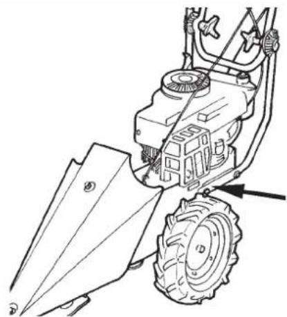
HOW TO MOUNT THE ACCELERATOR WIRE (Fig. 2) Position the lever (1) on the engine at the end of its stroke as shown by arrow "A., in the figure. Move the throttle lever (2) on the handlebar to the end of its stroke as shown by arrow "B., in the figure. Insert wire (3) into hole (4), secure the sheath (5) with retainer (6) and screw (7). ATTENTION: in the position "stop, the throttle lever must stop engine.
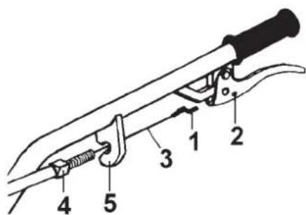
BELT STRETCHER DRIVING WIRE (Fig.5) Driving wire is already connected with the belt-stretching spring; have it connected to the lever on handlebar as follows: Insert the wire (3) and the register (4) in hole cut in the prong. Engage sheath terminal (1) into hole (2).
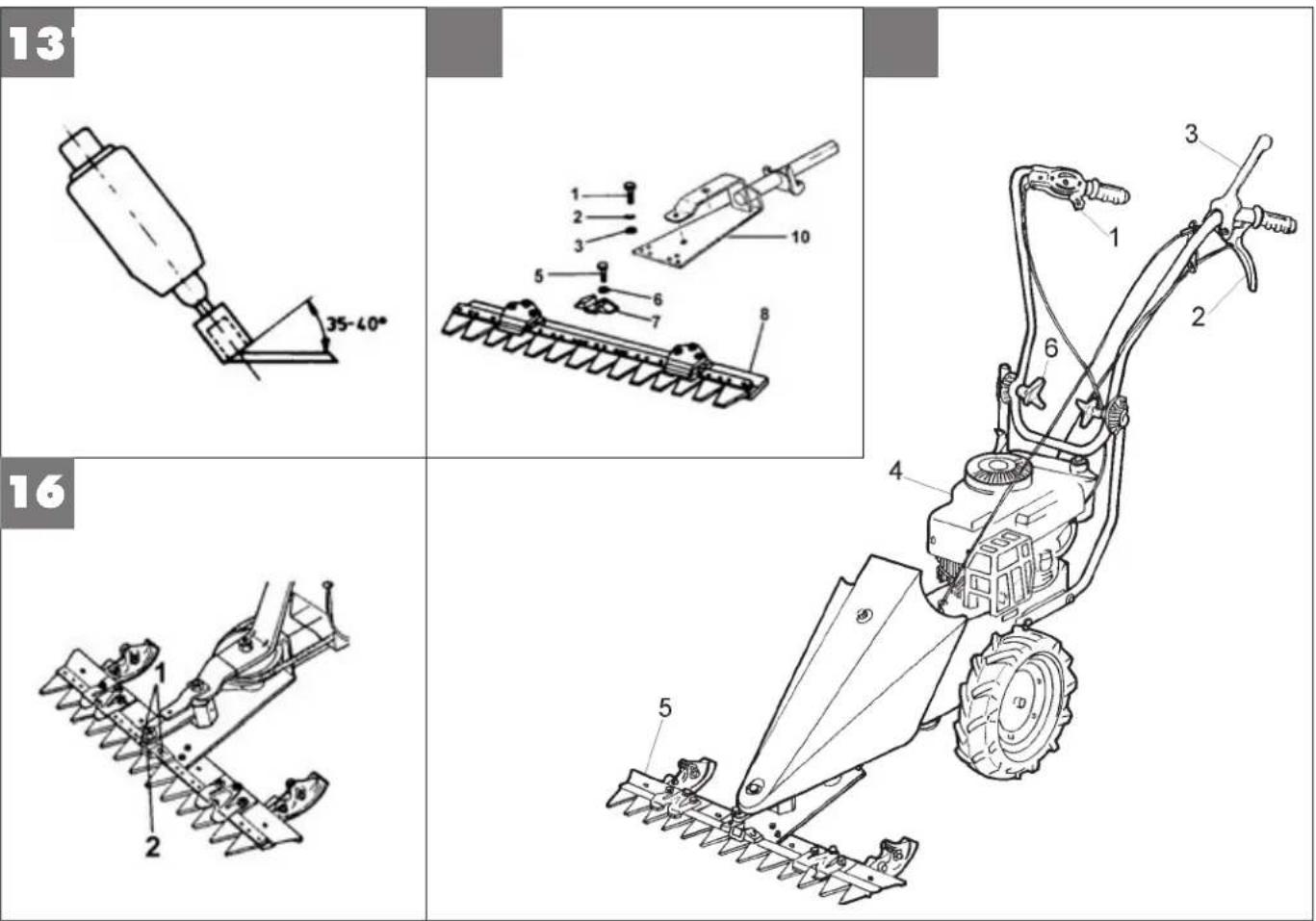
ASSEMBLING OF THE CUTTER BAR (Fig.10-14) For models equipped with 87 cm. cutting bar please complete the assembly adding the missing sliding part (part. 2 – fig. 10) you can find in the accessories envelope. In order to fix it please use the 2 screws (part 1), the washers and the nuts you can find on the cutting bar. Please refer also to chapter: "how to adjust the cutting bar height". To fix part (7) with the parts (5, 6) to the (8). Fix the part (10) with the parts (1, 2 and 3) to the (8). After about 2 hours of work to tighten the screws (5).
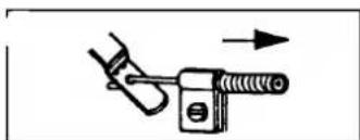
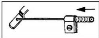
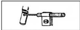
CORRECT ASSEMBLY OF THE BOWDEN ROD, ENGINE FUEL REGULATION (Fig. 3-4) Insert the opposite end of the Bowden rod down into the engine fuel lever. Now lightly clamp the jacketed end of the rod. Set the fuel lever on the handlebar to the start position


then set the fuel lever on the engine to the start position, right up to the stop point. Following this, definitively fix the jacketed end of the rod. Take care to prevent the rod from bending during the assembly phase. If the fuel lever fails to move freely, lubricate the rod with a few drops of oil and wait a few minutes to allow the oil to penetrate the casing. Now operate the fuel lever again.
ASSEMBLY OF THE CUTTING BAR TO THE UNIT (Fig. 6) The motor mower has a coupling for quick and easy attachment of the cutter bar and other accessories. The motor should be shut down and the machine horizontal. Insert the cutter bar pin (1) halfway into its seating (2). Install the belt (3) in its pulley by moving the guide pin all the way to the end of its travel. Attach the springs to their hooks (5), then to the holes (7). Replace the cowling (6) with its centering pin. Tighten home the nut with its washer on the cowling.
■ POSITIONING THE CUTTER BAR DRIVE BELT (Fig. 7) To increase the tension on the cutter bar drive belt between the machine and the attachment, set the register (2) so that the cutter bar will only begin to move when the control lever is over the halfway mark in its travel. Pull the left operating lever (1): forward drive.
BELT-STRETCHER CONTROL ADJUSTMENT (Fig. 8) Warning - Tyres should start rotating only when control lever is beyond halftravel; When lever is pulled to full extent (working position), the beltstretcher load spring (2) should extend by 6 to 8 mm approx. For above described conditions be reached, action is to be taken on nut (1) set close to the belt stretcher control assembly.
CUTTER BAR HEIGHT ADJUSTMENT (Fig. 10) Having to mow on uneven soils, you must adjust the cutter bar height. Proceed as follows: - Unloose nut (1), shift sliding block (2) in desired position, tighten nut (1). Perform this step on both sliding blocks.
■ REGULATING THE KNIFE (Fig. 9) After changing knife or after a certain number of work hours, the knife guide should be regulated by means of screws (1) and their locknut. To check the results after each regulation, first remove the cowling and then turn pulley (2) slowly by hand and check to make sure that the knife is moving easily.
MAINTENANCE Air filter This should be carried out in accordance with the attached motor maintenance instructions.
- GEARBOX (Fig. 11) Lube oil: SAE 80. The needed quantity for oil is about 0,18 lt. Check oil level before starting engine. Oil level should be checked by unscrewing the cap on the side of box. Check oil level every 60 hours of work.
CUTTER BAR TRANSMISSION (Fig. 12) Two greasing points (1-2). Important! Clean and grease blade bar and all moving parts every time after use.
MAINTENANCE OF THE CUTTER BAR The cutting mechanism is one of those pieces of agricultural equipment, which is placed under the most stress. It is obvious, therefore, that it must be particularly carefully serviced and correctly adjusted. It is advisable to clean the cutting mechanism after each use. To do this the cutting edge must be removed so that the dirt which has collected between the blades and cutting bars can be completely removed. Should the cutter bar not be in use for a longer period of time it should be sprayed with an anticorrosive agent. Although all

types of bar cutting mechanism are by and large resistant to the interference of stones and similar objects, it can occasionally happen that the bars and blades become damaged or bent. It is necessary, therefore, to check the condition of these parts each time you sharpen the cutting blade - after 4-6 hours of mowing depending on the work load.
Any damage must be made good and bent bars or blades repaired. Only well aligned bars and blades can guarantee a clean cut. At this point the track directions of the cutting edges should also be checked and too much play in the direction be removed by means of adjustment. Important when adjusting the directions of the cutting edges- adjust one direction first and then the second. After the adjustment of each single direction the blade must be able to be freely moved to and fro by hand. Please pay attention to the following particular instructions!!!
SHARPENING THE CUTTING BLADE (Fig. 13) When the cutting blades are blunt (this will depend on work load) they must be re-ground. In order to do this, the cutting blade is removed from the bar and cleaned. It is essential to check whether the backs and edges of the blades are bent; if so, they must be re-aligned. Only then can sharpening begin. Suitable for this purpose is a hand grinder with about 15000 - 20000 revolutions per minute, in conjunction with a cup-shaped grinding point with a diameter of 25 mm and a length of about 35 mm. Only the front side (face) of the grinding point is used in grinding - in a movement from the back of the blade to the blade's edge. Cutter bar blades need a cutting angle of 35 - 40°.
CUTTING BLADE REPLACEMENT (Fig. 16) Unscrew (1), take the blade coupling out (2) and then remove the blade. To reassemble the blade, perform these operations backwards. Note - To achieve good cutting, blade must always be sharp.
DESCRIPTION (Fig. 15) 1) Start-Stop operating lever - 2) Drive operating lever - 3) Cutter bar clutching control lever - 4) Engine - 5) Cutter bar - 6) Handlebar adjusting knob.
TECHNICAL DETAILS Track: 430 mm - Length of cutter bar: 870 mm - Total length: 1350 mm - Total height: 1000 mm - Tires: 2 tires 4.00-6 - Mass: 53 kg. Motor - Cooling: air cooling - Fuel tank: 0,75 Litre. Please consult the relative instruction manual for other technical information and details about the engine.
NOISE AND VIBRATION LEVEL Measured sound pressure level with En12733, Leq = 90,8 dB (A), with a uncertainty value K = ±1,2 dB (A). Measured sound power level with En12733, Lwa = 102 dB (A), with a uncertainty value K = ±1,4 dB (A). Handlebar vibration in compliance with EN 12733. Level max detected = 24,8 m/s², uncertainty value K = ±12,4 m/s².


FAULT
Before performing any maintenance and clearing work operation, please take the spark-plug cap off.!
| FAULT FAULT CLEARANCE | |
| The engine does not start check the fuel level, if necessary refuel. | |
| The engine power goes down the air filter is dirty – please clean it | |
| The grass cut is irregular sharpen or replace the cutting blade | adjust the cutting bar clearance |
| The cutting bar does not work or the wheels are not turning adjust the cutting bar cable | |
| In case you are not able to remedy the defect/damage according to a.m. table, please contact an authorized service center only . | |
GB Warranty: The warranty rules issued by our company or the importer apply to every country. As part of the warranty, we remedy malfunctions on your appliance free of charge provided that this malfunction is caused by a material or manufacturing defect. In the event of a warranty claim, please turn to your dealer or the nearest branch office. Engine: The manufacturer of the engine is liable for all engine-related problems with respect to output power, power measurement, specifications, warranties, and service. More detailed information can be found in the owner / operator handbook provided separately by the engine manufacturer.
MTD International France
B.P. 453 Saint-Etienne du Rouvray
76806 Cedex
02 32 91 94 32
02 32 91 94 36
EN
E.P.Barrus LTD
Launton Road
OX6 OUR Bicester, Oxfordshire
0 18 69 36 36 36
0 18 69 36 36 20
RUS
MTD Poland sp. z o.o.
UL. Ogrodnicza 1
84-252 Orle
058 57 20 701
058 57 20 699