
FMHT77357 - Laser level STANLEY - Free user manual and instructions
Find the device manual for free FMHT77357 STANLEY in PDF.



| Brand | Stanley |
| Model | FMHT77357 (red), FMHT77356 (green) |
| Product Type | Self-leveling rotary laser level |
| Leveling Accuracy | ≤ 3 mm at 10 m (1/8" at 30 ft) |
| Horizontal/Vertical Accuracy | ≤ 3 mm at 10 m (1/8" at 30 ft) |
| Compensation Range | ± 4° |
| Operating Range (line) | Red: 20 m (50 m with detector) / Green: 35 m (50 m with detector) |
| Laser Class | Class 2 (IEC/EN 60825-1:2014) |
| Wavelength | Red: 630-680 nm / Green: 510-530 nm |
| Operating Time (all lasers on) | ≥ 24 h (Li-Ion) for red, ≥ 8 h for green |
| Power Source | Built-in Li-Ion battery pack 7.2 V DC, 2.0 Ah, 14.4 Wh |
| Mains Power Supply | Huntkey HKA03612030-8C charger (100-240 V AC, 50/60 Hz) |
| Charging Time | Approx. 3 hours (at 18-24 °C) |
| Protection Rating | IP54 |
| Operating Temperature Range | -10 °C to +40 °C (14 °F to 104 °F) |
| Storage Temperature Range | -20 °C to +40 °C (-4 °F to 104 °F) |
| Charging Temperature Range | 5 °C to +40 °C (41 °F to 104 °F) |
| Dimensions (approx.) | Not specified in manual – estimated 150x120x100 mm |
| Weight (approx.) | Not specified – estimated 1.5 kg with battery |
| Housing Material | Reinforced plastic |
| Mounting Thread | 1/4-20 and 5/8-11 threads |
| Maintenance | Clean with a soft, dry cloth; do not use solvents |
| Warranty | Refer to the provided warranty manual |
Frequently Asked Questions - FMHT77357 STANLEY
User questions about FMHT77357 STANLEY
0 question about this device. Answer the ones you know or ask your own.
Ask a new question about this device
Download the instructions for your Laser level in PDF format for free! Find your manual FMHT77357 - STANLEY and take your electronic device back in hand. On this page are published all the documents necessary for the use of your device. FMHT77357 by STANLEY.
USER MANUAL FMHT77357 STANLEY
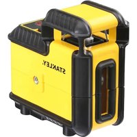
Self-Leveling Multi-Line Laser
3 x 360 Line Laser
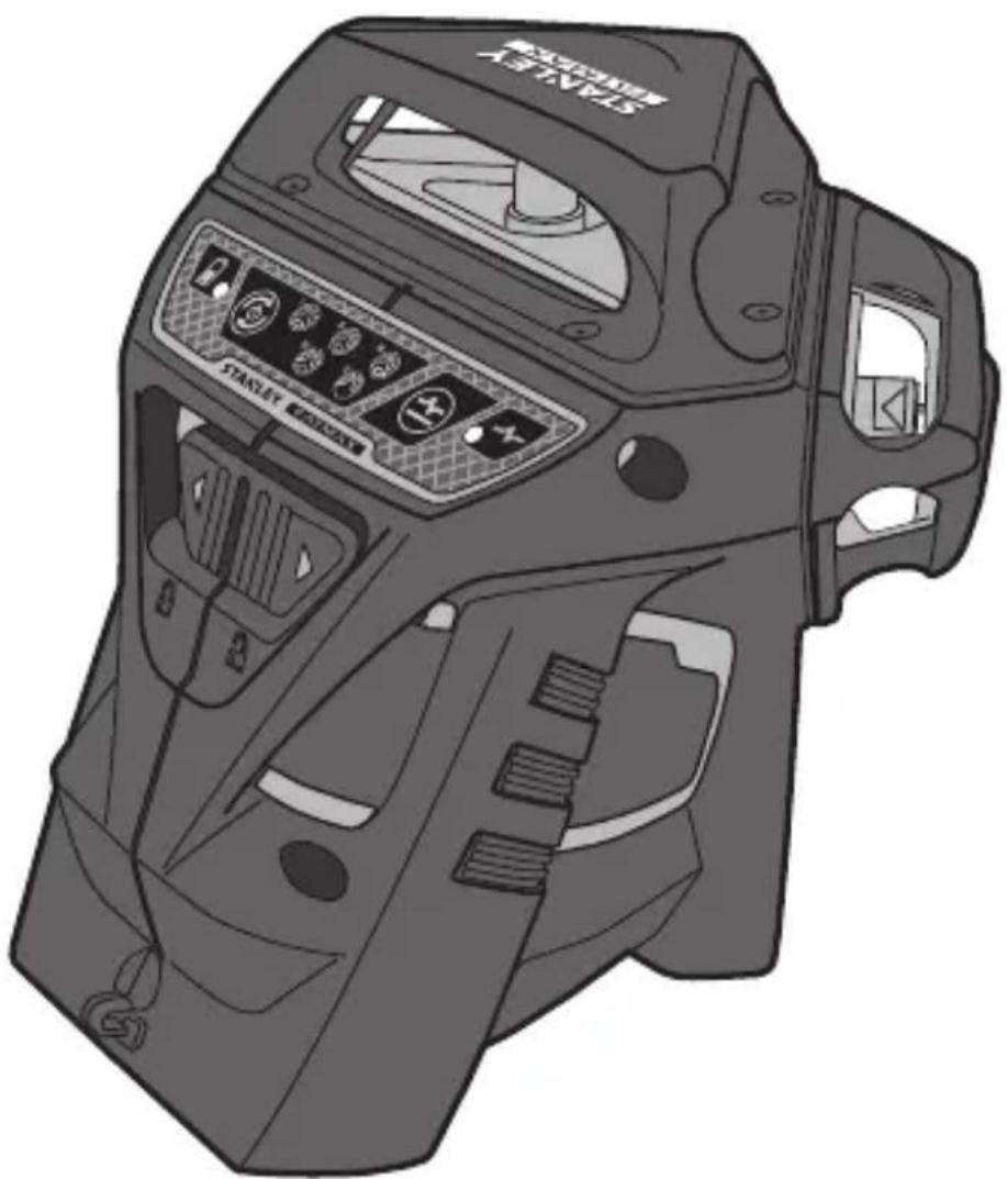
natural_image
Illustration of a black-and-white photo of a mechanical device with control panel and buttons (no text or symbols)www.2helpU.com

natural_image
Four black-and-white icons representing safety and communication symbols: helmet, crosshair, target, and person (no text or labels)Please read these instructions before operating the product
Figures
F
Figures
G

H
1
2
3
GB
Contents
- User Safety
- Contents
- Product Overview
• Keypad, Modes, and LED - Applications
• Batteries, Safety and Power
• Power Supply Operation and Safety - Set Up
- Operation
• Accuracy Check and Calibration - Specifications
Retain all sections of the manual for future reference.
User Safety

WARNING:
Read all safety warnings and instructions included in the Safety Instructions and User Manuals before using this product. Failure to follow the warnings and instructions may result in electric shock, fire and/or serious injury."The person responsible for the instrument must ensure that all users understand and adhere to these instructions.

CAUTION
Use of controls or adjustments or performance of procedures other than those specified herein may result in hazardous radiation exposure.

WARNING:
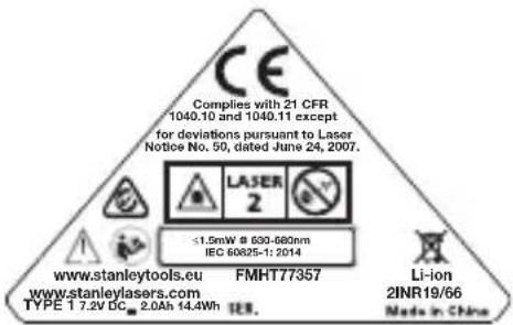
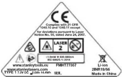
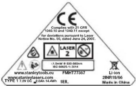
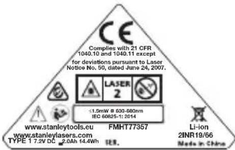
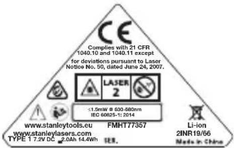
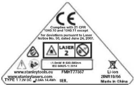
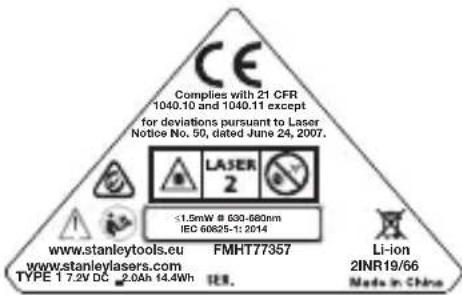
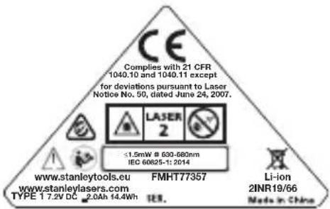
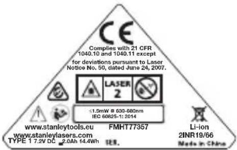
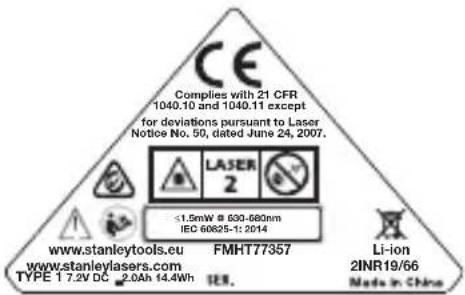
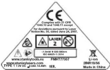
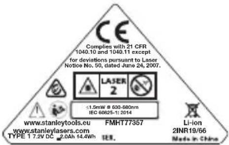
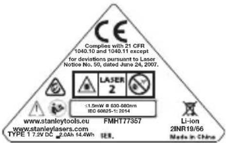
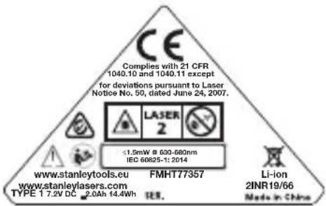
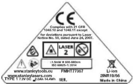
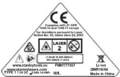
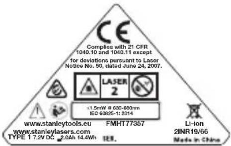
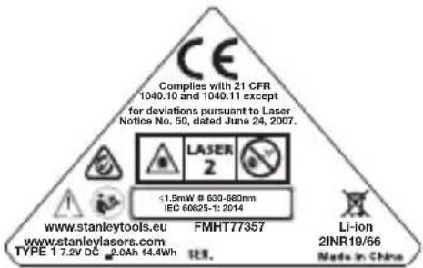
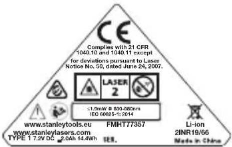
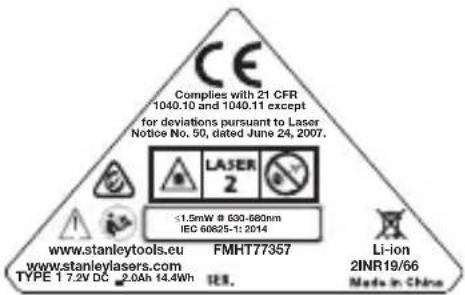
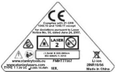
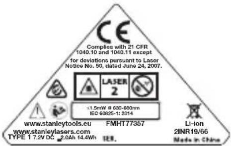
The following labels are placed on the laser tool to inform you of the laser class for your convenience and safety.

IEC /EN 60825-1:2014
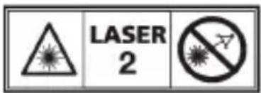
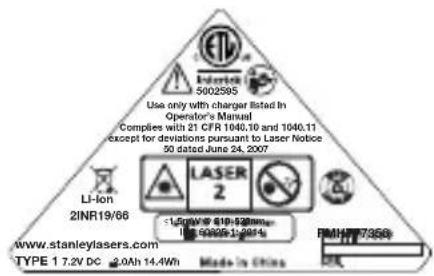
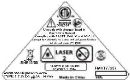

WARNING: LASER RADIATION. DO NOT STARE INTO BEAM. CLASS 2 LASER PRODUCT.

CAUTION:
While the laser tool is in operation, be careful not to expose your eyes to the emitting laser beam Exposure to a laser beam for an extended time may be hazardous to your eyes.

CAUTION:
Glasses may be supplied in some of the laser tool kits. These are NOT certified safety glasses. These glasses are ONLY used to enhance the visibility of the beam in brighter environments or at greater distances from laser source.

WARNING There are no user serviceable parts inside. Do not attempt repairs. Return the product to your local service center for assistance.

WARNING To reduce the risk of injury, user must read the Product User manual, Laser Safety and Battery Safety manuals.

CAUTION-Recycle per your local regulations for Li-Ion batteries or return the product to your local service center

Li-ion
2INR19/66
Compliance
This product complies with 21 CFR 1040.10 and 1040.11 except for deviations pursuant to laser Notice 50, dated June 24, 2007.
Conforms to UL STDS 61010-1 & 2595
Certified to CSA STD C22.2 No. 61010-1
Product Overview
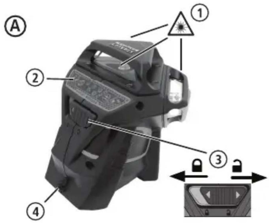
Figure A - Laser Tool
- Laser Window/Aperture
- Keypad Switch
- Power/pendulum Lock Switch
- DC Power supply jack
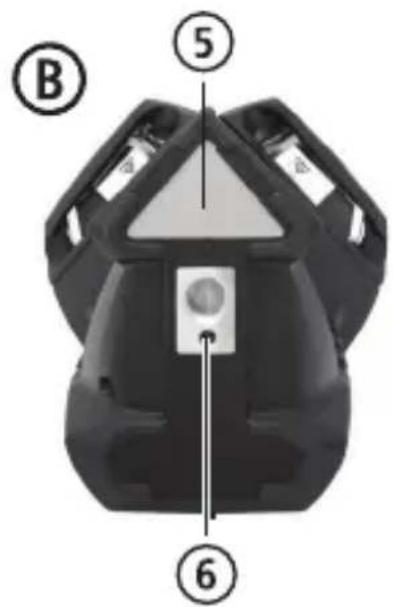
Figure B - Power /Transport Lock
- Label
- 1/4-20 and 5/8-11 threaded mount
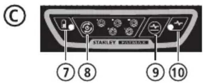
Figure C - Keypad and Laser Modes
- Battery/Power
- Beam Activation Key
- Pulse Mode Activation Key
- Pulse Mode/Out of level indicator LED
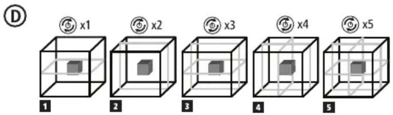
Figure D - Beam Options
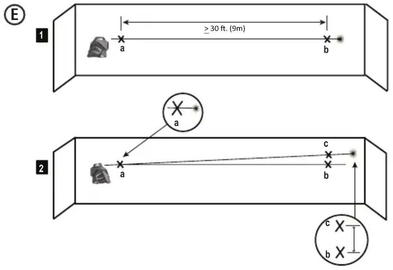
Figure E - Horizontal Beam Scan Direction Accuracy
Figure F - Horizontal Beam Pitch Direction Accuracy
Figure G - Vertical Beam Accuracy
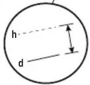
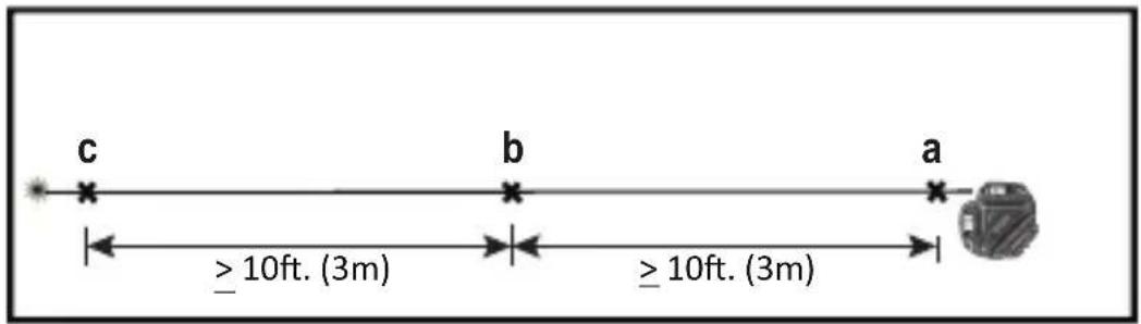
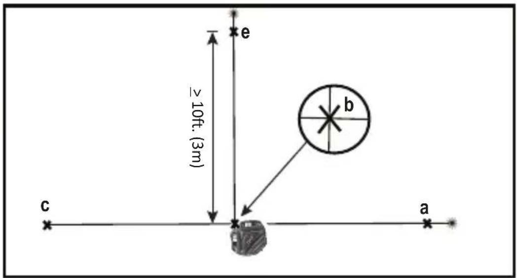
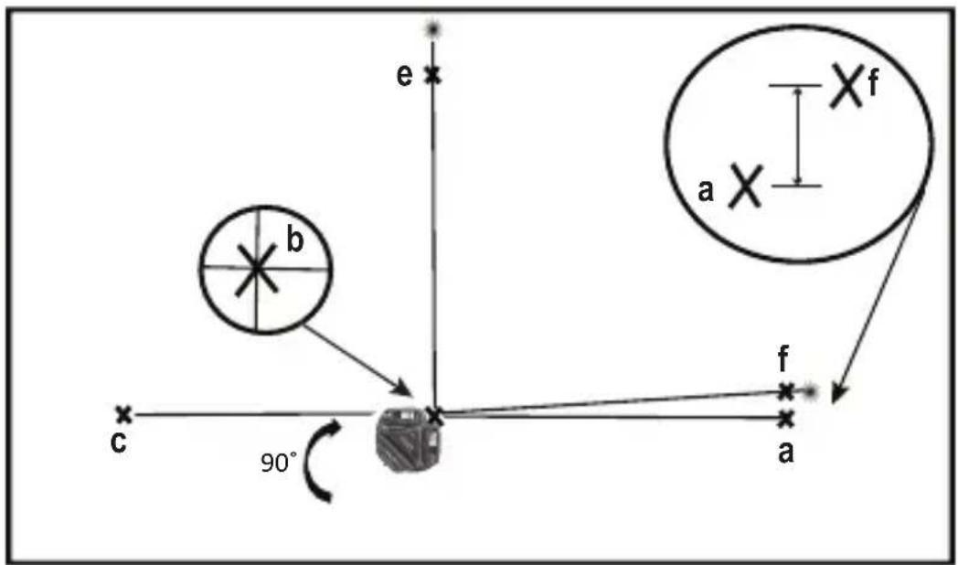
Figure H - Vertical Beam 90° Accuracy
Keypad, Modes, and LED
Power /Pendulum Lock Switch (Fig B)

Power ON/Pendulum lock off /Self-leveling On

Power OFF/Pendulum lock on
- To turn the laser tool ON move switch to the unlocked position
- To turn the laser tool OFF, move switch to the locked position
Modes
Laser Beam Available Modes.
See Figures C and D for beam configuration.
Self-Leveling (Fig B)
- The pendulum lock on the laser tool needs to be switched to the unlocked /ON position to enable self-leveling when placed in a position <4^ .
Out of Level (Fig B)
- If the laser has been tilted >4^ then it cannot self-level and the laser beam will flash.
Keypad-Pulse key.

Pulse mode ON/OFF key
figure )

Press to activate Pulse mode.
(See figure ©# 9)
Pulse Mode LED/Out-of-Level Indicator Operation (See figure ©# 10)

LED OFF
- Pulse Mode is OFF/ Unit is level
LED ON-CONTINUOUS GREEN
- PULSE MODE is ON, and laser unit is within self-leveling range. (<4 °)
LED ON-FLASHING RED
- Laser unit is OUT OF LEVEL and beams will flash. (PULSE MODE may be ON or OFF depending on initial state set.)
Keypad-Battery key

Battery level indicator key
(See figure Ⓐ)
Battery Life LED
(See figure Ⓞ7)
LED ON-CONTINUOUS GREEN
- Battery life >25%
LED ON-FLASHING RED
- Battery life <25%
LED OFF
- Battery needs recharging. Laser Beams shut off.
Applications
Plumb Transfer
- Using the vertical laser beam, establish a vertical reference plane.
- Position the desired object(s) until they are aligned with the vertical reference plane to ensure object(s) are plumb.
Level Transfer
- Using the horizontal laser beam, establish a horizontal reference plane.
- Position the desired object(s) until they are aligned with the horizontal reference plane to ensure object(s) are level.
Square
- Using the vertical and horizontal laser beams, establish a point where the two beams cross.
- Position the desired object(s) until they are aligned with both the vertical and horizontal laser beams to ensure objects(s) are square.
Batteries, Safety and Power

WARNING:
Read all safety warnings and instructions included in the accompanying Safety Instructions and User Manuals before using this product. Failure to follow the warnings and instructions may result in electric shock, fire and/or serious injury." The person responsible for the instrument must ensure that all users understand and adhere to these instructions.
- Prevent unintentional start up. Ensure the switch is in the off-position before picking up or carrying the device. Carrying the device with your finger on the switch or energizing the unit with the switch in the on position invites accidents.
- The laser should only be recharged with the power supply provided by connecting it to the DC power supply jack shown in Figure A#4 (Power supply: Huntkey Model # HKA03612030-8C) A charger that is suitable for one type of product or battery pack may create a risk of fire when used with another product or battery pack.
- The laser comes with an integrated and rechargeable Li-Ion battery pack which is not user replaceable or serviceable. Do not attempt to install any other battery packs as this may create a risk of injury and fire.
- When device is not in use, keep it away from other metal objects, like paper clips, coins, keys, nails, screws or other small metal objects, that can make a connection from one terminal to another. Shorting the battery terminals together may cause burns or a fire. Ensure the DC power supply jack is closed with the attached rubber plug when not in use.
- Under abusive conditions, liquid may be ejected from the integrated batteries; avoid contact. If contact accidentally occurs, flush with water. If liquid contacts eyes, additionally seek medical help. Liquid ejected from the batteries may cause irritation or burns.
- Do not use the device if damaged or modified. Damaged or modified Li Ion battery powered product may exhibit unpredictable behavior resulting in fire, explosion or risk of injury.
- Do not expose a battery pack or appliance to fire or excessive temperature. Exposure to fire or temperature above 130°C (265°F) may cause explosion. See recommended temperatures in the Specifications Table.
- The laser product is not user serviceable and should be returned to your distributor or Stanley Warranty/Service Center in the event of failure or damage. Any service applicable should be performed by a qualified repair person using only identical replacement parts. This will ensure that the safety of the product is maintained.
- Please read all related instructions and warnings in the accompanying Battery Safety and Laser Safety/Warranty manuals. Follow all local regulations for disposal of the product at the end of its life.
Power Supply Operation and Safety
Important Safety Instructions for Power Power supply/ Supply.
SAVE THESE INSTRUCTIONS:
Your tool uses a power supply operating between 100-240V AC @50/60Hz.
Before using the power supply, read all safety instructions and cautionary markings on power supply, and product before using your power supply.

WARNING: Shock hazard. Do not allow any liquid to get inside power supply. Electric shock may result.

CAUTION: Burn hazard.
- NOTICE: Under certain conditions, with the power supply plugged in to the power supply, the power supply can be shorted by foreign material. Foreign materials of a conductive nature such as, but not limited to, grinding dust, metal chips, steel wool, aluminum foil, or any buildup of metallic particles should be kept away from power supply cavities.
- Always unplug the power supply from the power supply when not in use. Unplug power supply before attempting to clean. Clean only with a soft dry cloth
- DO NOT attempt to charge the product with any power supplys other than the one provided with your product. The power supply and integrated battery pack are specifically designed to work together.
- The power supply provided with your laser is not intended for any uses other than charging the Fatmax laser. Any other uses may result in risk of fire, electric shock or electrocution. Use only HUNTKEY Model # HKA03612030-8C
- Store power supply out of reach of children.
- Do not expose power supply to rain or snow.
- Pull by plug rather than cord when disconnecting power supply. This will reduce risk of damage to electric plug and cord.
-
Do not place any object on top of power supply that might result in excessive internal heat. Place the power supply in a position away from any heat source.
-
Do not operate power supply with damaged cord or plug.
- Do not operate power supply if it has received a sharp blow, been dropped, or otherwise damaged in any way. Take it to an authorized service center.
- Do not disassemble power supply; take it to an authorized service center if service or repair is required.
- The power supply is designed to operate on 100-240V AC @50/60Hz.
- Do not attempt to use it on any other voltage.
- Refer to Battery Safety Manual for additional instructions.
Charging Procedure
- Plug the power supply into an appropriate outlet before connecting to laser unit.
- Insert the charging cable into the charging port on the rear of the laser unit.
NOTE: A battery pack will slowly lose its charge when left idle for extended periods of time. The product may need to be recharged before use.
Important Charging Notes
The power supply may become warm to touch while charging. This is a normal condition, and does not indicate a problem. To facilitate the cooling of the battery pack after use, avoid placing the power supply or battery pack in a warm environment such as in a metal shed, or an uninsulated trailer.
If the internal battery does not charge properly:
a. Check operation of receptacle by plugging in a lamp or other appliance;
b. Check to see if receptacle is connected to a light switch which turns power off when you turn out the lights;
c. Move power supply and laser unit to a location where the surrounding air temperature is approximately 65 °F - 75 °F (18 °- 24 °C);
d. If charging problems persist, take the tool, and power supply to your local service center.
- Do not freeze or immerse power supply in water or any other liquid.

WARNING: Shock hazard. Don't allow any liquid to get inside power supply. Electric shock may result.
CAUTION: Never attempt to open the power supply or any reason. The product has no user serviceable parts inside.
Set Up
Laser Tool
- Place laser tool on a flat, stable surface.
- To power ON and activate the auto leveling feature move the pendulum / transport lock to the unlocked position. (Fig B #3)
- The laser tool must then be positioned in its upright position on a surface that is within the specified compensation range.
- Select the desired beam configuration by pressing the beam activation key (Figure C #8) repeatedly and cycling through the options shown in Figure D.
Mounting on Accessories
- Position accessory in a place where it will not be easily disturbed and near the central location of the area to be measured.
- Set up the accessory as required. Adjust positioning to be sure accessory base is near horizontal (within laser tools compensation range).
- Mount the laser tool to the accessory using the appropriate fastening method to be used with such accessory / laser tool combination.

CAUTION:
- Do not leave the laser tool unattended on an accessory without fully tightening the fastening screw. Failing to do so may lead to the laser tool falling and sustaining possible damage.
NOTE:
- It is best practice to always support laser tool with one hand when placing or removing laser tool from an accessory.
- If positioning over a target, partially tighten the fastener, align laser tool, and then fully tighten.
Operation
NOTE:
- Before operating the laser tool always be sure to check the laser tool for accuracy.
- Laser tool will indicate when it is out of compensation range. Reference LED Descriptions. Reposition laser tool to be closer to level.
- When not in use, please be sure to power OFF the laser tool by placing the pendulum lock in the locked position.
Power
- To turn the laser ON move the pendulum / transport lock to the unlocked position.(Fig B #3)
- To turn the laser OFF, move the pendulum / transport lock to the locked position.
- Select the desired beam configuration by pressing the beam activation key (Figure C #8) repeatedly and cycling through the options shown in Figure D.
Modes
OFF/ Locked (See figures Ⓑ)
- The laser will be OFF and the pendulum locked.
ON/ Self-Leveling (See figures B)
- The pendulum lock on the laser tool will be positioned in the unlocked /self-leveling position when the laser is turned ON. - The lasers are designed to self-level. If the laser has been tilted >4^ then it cannot self-level and the laser beam will flash. When the beams flash THE LASER IS NOT LEVEL (OR PLUMB) AND SHOULD NOT BE USED FOR DETERMINING OR MARKING LEVEL OR PLUMB. Try repositioning the laser on a more level surface.
Accuracy Check and Calibration
- The laser tools are sealed and calibrated at the factory to the accuracies specified.
- It is recommended to perform a calibration check prior to its first use and then periodically during future use.
-
The laser tool should be checked regularly to ensure its accuracies, especially for precise layouts.
-
When performing the accuracy checks, use the largest area / distance possible, closest to the operating distance. The greater the area / distance, the easier to measure the accuracy of the laser.
- The lock must be in the unlocked position to allow the laser tool to self-level before checking the accuracy.
- Place the laser on a smooth, flat, stable surface that is level in both directions.
CHECKING ACCURACY – HORIZONTAL BEAM,
SCAN DIRECTION (FIG. E)
Checking the horizontal scan calibration of the laser requires two walls 30' (9m) apart. It is important to conduct a calibration check using a distance no shorter than the distance of the applications for which the tool will be used.
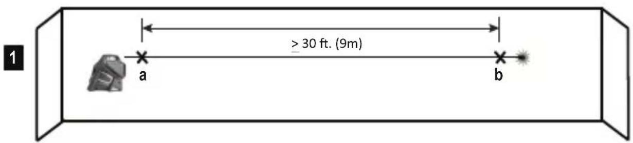
- Place the laser against the end of a 9m (30') wall (Figure E #1).
- Turn the laser ON.
- Display a horizontal laser beam.
- Turn the laser toward the opposite end of the wall and parallel to the adjacent wall.
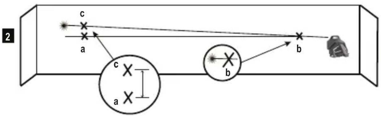
- At least 9m (30') apart on the laser beam, mark a and b.
- Turn the laser 180°.
- Adjust the height of the laser so the center of the beam is aligned with a (Figure E#2).
- Directly above or below ⓑ, mark Ⓒ along the laser beam (Figure E #3).
- Measure the vertical distance between ① and ②.
- If your measurement is greater than the Allowable Distance Between ⓑ and Ⓒ for the corresponding Distance Between Walls in the following table, the laser must be serviced at an authorized service center.
| Distance Between Walls | Allowable Distance Between b and c |
| 9m (30') 6mm (1/4") | |
| 12m (40') 8mm (5/16") | |
| 15m (50') 10mm (13/32") | |
CHECKING ACCURACY – HORIZONTAL BEAM, PITCH DIRECTION (FIG. F)
Checking the horizontal pitch calibration of the laser requires a single wall at least 30' (9m) long. It is important to conduct a calibration check using a distance no shorter than the distance of the applications for which the tool will be used.
- Place the laser against the end of a 9m (30') wall (Figure F #1).
- Turn the laser ON.
- Display a horizontal laser beam.
- Turn the laser toward the opposite end of the wall and parallel to the adjacent wall.
- At least 9m (30') apart on the laser beam, mark a and b
- Move the laser to the opposite end of the wall (Figure F #2).
- Position the laser toward the first end of the same wall and parallel to the adjacent wall.
- Adjust the height of the laser so the center of the beam is aligned with b.
- Directly above or below a mark c along the laser beam (Figure F #3).
- Measure the distance between a and c.
- If your measurement is greater than the Allowable Distance Between a and c for the corresponding Distance Between Walls in the following table, the laser must be serviced at an authorized service center.
| Distance Between Walls | Allowable Distance Between a and c |
| 9m (30') 6mm (1/4") | |
| 12m (40') 8mm (5/16") | |
| 15m (50') 10mm (13/32") | |
GB
CHECKING ACCURACY – VERTICAL BEAMS (FIG. G)
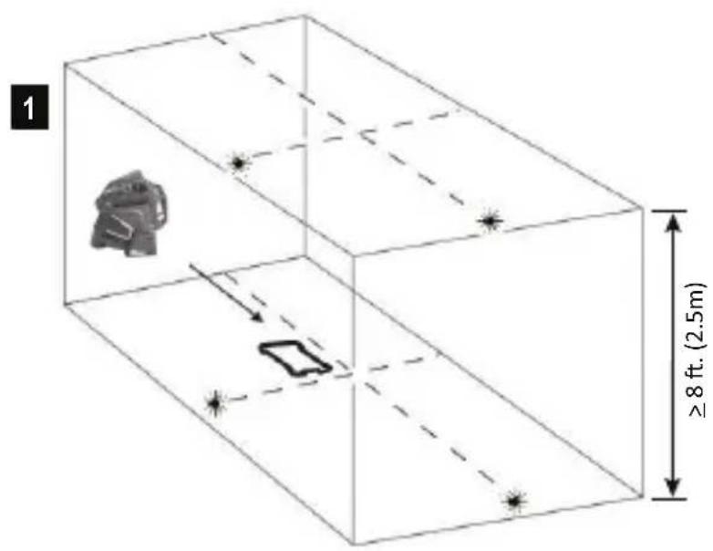
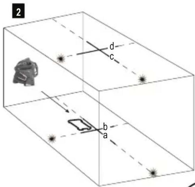
Checking the vertical (plumb) calibration of the laser can be most accurately done when there is a substantial amount of vertical height available, ideally 30' (9m), with one person on the floor positioning the laser and another person near a ceiling to mark the position of the beam. It is important to conduct a calibration check using a distance no shorter than the distance of the applications for which the tool will be used.
- Place the laser on a smooth, flat, stable surface that is level in both directions and turn on both vertical beams (Figure G #1).
- Mark two short lines where the beams cross (a, b) and also on the ceiling c, d. Always mark the center of the beams' thickness (Figure G #2).
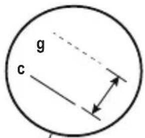
- Pick up and rotate the laser 180°, and position it so the beams line up with the marked lines on the level surface (e, f) (Figure G #3).
- Mark two short lines where the beams cross on the ceiling g, h.
- Measure the distance between each set of marked lines on the ceiling (c, g and d, h). If the measurement is greater than the values shown below, the laser must be serviced at an authorized service center.
| Ceiling Height | Allowable Distance Between Marked Lines |
| 2.5 m (8') 1.5 mm (1/16") | |
| 3 m (10') 2.0 mm (3/32") | |
| 4 m (14') 2.5 mm (1/8") | |
| 6 m (20') 4 mm (5/32") | |
| 9 m (30') 6 mm (1/4") |
CHECKING 90° ACCURACY BETWEEN VERTICAL BEAMS (FIG. H)
Checking 90° accuracy requires an open floor area at least 33' x 18' (10m x 5m). Refer to Figure H for the position of the laser at each step and for the location of the marks made at each step. Always mark the center of the beams' thickness.
-
Place the laser on a smooth, flat, stable surface that is level in both directions, as shown in Figure H #1.
-
Turn the laser ON.
- Turn on both vertical beams.
- Along the front laser beam, mark three locations a, b, and c; where b is at the midpoint of the laser beam.
- Position the laser so the down dot is over b and the front laser beam is aligned with c (Figure H #2).
- Mark a location e along the side laser beam at least 3m (10') away from the laser.
- Turn the laser clockwise 90°.
- Position the laser so the down dot is over b and the front laser beam is aligned with e (Figure H #3).
- Along the side laser beam, mark f near a
- Measure the distance between a and f
- If your measurement is greater than the Allowable Distance Between a & f for the corresponding Distance from b to a in the following table, the laser must be serviced at an authorized service center.
| Distance fromb to a | Allowable DistanceBetween a & f |
| 3m (10') 3.2mm (1/8") | |
| 4m (14') 3.5mm (5/32") | |
| 5m (17') 4.5mm (3/16") | |
| 6m (20') 5.5mm (7/32") | |
| 7m (23') 6mm (1/4") |
Specifications
Laser Tool
| FMHT77357(RED) FMHT77356(GREEN) | ||
| Levelling Accuracy: ≤3 mm / 10m (1/8in @ 30 ft) | ||
| Horizontal / Vertical Accuracy ≤3mm / 10m (1/8in @ 30 ft) | ||
| Compensation Range: ±4° | ||
| Working Distance (Line): RED: 20 m (65ft)(50 m with detector) | GREEN: 35m (115ft)(50 m with detector) | |
| Laser Class: Class 2 (IEC/EN60825-1: 2014 | ||
| Laser Wavelength 630-680nm (RED) 510 nm ~ 530 nm (GREEN) | ||
| Operating Time (All lasers ON): ≥ 24hours (Li Ion) ≥ 8hours (Li Ion) | ||
| Power Source: Integrated Li Ion Battery pack; 7.2V DC; 2.0Ah; 14.4Wh | ||
| IP Rating: IP54 | ||
| Temperature Range (Operating): 10°C ~ +40°C (50°F~104°F) | ||
| Temperature Range (Storage): -20°C ~ +40°C (-4°F~104°F) | ||
| Temperature Range (Charging): | 5°C ~ +40°C (41°F~104°F) | |
Inhalt
D
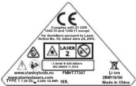


AVERTISSEMENT : RAYONNEMENT LASER. NE REGARDEZ PAS DIRECTEMENT LE FAISCEAU. PRODUIT LASER DE CLASSE 2.

ATTENTION :

AVVERTENZA: RADIAZIONE LASER. NON FISSARE IL RAGGIO. PRODOTTO LASER CLASSE 2.

ATTENZIONE:
| 9 m (30') 6 mm | (1/4") |
CONTROLLO PRECISIONE 90° TRA I RAGGI VERTICALI (FIG. H)



WAARSCHUWING: LASERSTRALING. Kijk NIET IN DE LASERSTRAAL. KLASSE 2 LASER PRODUCT.

LET OP:

ADVARSEL: LASERSTRÅLING KIG IKKE IND I STRÅLEN. KLASSE 2 LASERPRODUKT.

FORSIGTIG:

WARNING: LASERSTRÅLNING STIRRA INTE IN I LASERSTRÅLEN, KLASS 2 LASERPRODUKT.

FÖRSIKTIGHET:

VAROITUS: LASERSÄTEILY. ÄLÄ KATSO SÄTEESEEN. LUOKAN 2 LASERTUOTE.

HUOMIO:

ADVARSEL: LASERSTRÅLING, IKKE SE INN I STRÅLEN. KLASSE 2 LASERPRODUKT.

FORSIKTIG:


| 3 m (10') 2,0 mm (3/32") |
| 4 m (14') 2,5 mm (1/8") |
| 6 m (20') 4 mm (5/32") |
| 9 m (30') 6 mm (1/4") |

VAROVÁNÍ: LASEROVÉ ZÁŘENÍ. NEDÍVEJTE SE DO LASEROVÉHO PAPRSKU. LASEROVÝ VÝROBEK TŘÍDY 2.

UPOZORNĚNÍ:
TYTO POKYNY USCHOVEJTE:



FIGYELMEZTETÉS: LÉZERSUGÁRZÁS, NE NÉZZEN A SUGÁRBA. 2. OSZTÁLYÚ LÉZERTERMÉK.

VIGYÁZAT:

VAROVANIE: LASEROVÁ RADIÁCIA. NEPOZERAJTE DO LÚČA. LASEROVÝ PRODUKT TRIEDY 2.

UPOZORNENIE:

OPOZORILO: LASERSKO SEVANJE NE GLEJTE NEPOSREDNO V LASERSKI ŽAREK LASERSKE NAPRAVE RAZREDA 2.

SVARILO:


AVERTISMENT: RADIATII LASER. NU NU PRIVITI ÎN FASCICUL PRODUS. LASER DE CLASA 2.

ATENTIE:
| DistanțăÎntre peřeți | Distanța permisăÎntre marcaje |
| 8' (2,5m) 1/16" (1,5mm) | |
| 10' (3,0m) 3/32" (2,0mm) | |
| 14' (4,0m) 1/8" (2,5mm) | |
| 20' (6,0m) 5/32" (4,0mm) | |
| 30' (9,0m) 1/4" (6,0mm) |
RO
VERIFICAREA PRECIZIEI 90° ÎNTRE FASCICULELE VERTICALE (FIG. H)

HOIATUS! LASERIKIIRGUS. ÄRGE VAADAKE OTSE LASERIKIIRDE. 2. KLASSI LASERSEADE.

ETTEVAATUST!
HOIDKE NEED JUHISED ALLES:

BRĪDINĀJUMS! LĀZERA STAROJUMS. NESKATIETIES STARĀ. KLASES 2 LĀZERA IZSTRĀDĀJUMS

UZMANĪBU!

ISPÉJIMAS: LAZERIO SPINDULIAVIMAS. NEŽIÜRÉKITE I SPINDULI. 2 KLASÉS LAZERINIS GAMINYS.

DÈMESIO!


UPOZORENJE: LASERSKO ZRAČENJE, NEMOJTE GLEDATI U ZRAKU - LASERSKI PROIZVOD KLASE 2.

OPREZ:
Dok je laserski alat u upotrebi, pazite da ne izlažete oči laserskoj zraci. Dulje izlaganje laserskoj zraci može biti opasno za oči.

PAŽNJA:
U nekim kompletima laserskih alata mogu biti isporučene naočale. One NISU certificirane sigurnosne naočale. Te naočale koriste se SAMO za poboljšanje vidljivosti zrake u svijetlim okruženjima ili na većim udaljenostima od izvora laserske zrake.

UPOZORENJE U unutrašnjosti nema dijelova koje bi korisnik mogao servisirati. Ne pokušavajte samostalno izvoditi popravke. U slučaju potrebe obratite se lokalnom ovlaštenom servisu.

UPOZORENJE Da biste smanjili rizik od ozljede, obavezno pročitajte Priručnik za upotrebu te priručnike za sigurnost lasera i sigurnu upotrebu baterije.

NAPOMENA-Reciklirajte prema lokalnim propisima za litij-ionske baterije ili vratite proizvod u lokalni servis.
Pregled proizvoda
Slika A - laserski alat
- Prozorčić/otvor lasera
- Prekidač tipkovnice
- Prekidač za napajanje/blokiranje njihanja
- Priključak DC napajanja
Slika B - napajanje/blokada pomicanja
- Oznaka
- Navojni priključak 1/4-20 i 5/8-11
Slika C - tipkovnica i načini rada lasera
- Baterija/napajanje
- Tipka za aktivaciju zrake
- Tipka za aktivaciju pulsiranja
- Lampica indikacije načina pulsiranja / uređaja izvan nivelacije
© 2017 Stanley Black & Decker
Stanley Europe, Egide Walschaertsstraat 14-16,
2800 Mechelen, Belgium
www.2HELPU.com
DOC100270398 - Rev A
August 2017
- Self-Leveling Multi-Line Laser
- x 360 Line Laser
- GB
- Contents
- User Safety
- WARNING:
- CAUTION
- CAUTION:
- Compliance
- Product Overview
- Figure A - Laser Tool
- Figure B - Power /Transport Lock
- Figure C - Keypad and Laser Modes
- Figure D - Beam Options
- Keypad, Modes, and LED
- Power /Pendulum Lock Switch (Fig B)
- Modes
- Laser Beam Available Modes.
- Self-Leveling (Fig B)
- Out of Level (Fig B)
- Keypad-Pulse key.
- Pulse Mode LED/Out-of-Level Indicator Operation (See figure ©# 10)
- LED OFF
- LED ON-CONTINUOUS GREEN
- LED ON-FLASHING RED
- Keypad-Battery key
- Battery Life LED
- Applications
- Plumb Transfer
- Level Transfer
- Square
- Batteries, Safety and Power
- Power Supply Operation and Safety
- SAVE THESE INSTRUCTIONS:
- Charging Procedure
- Important Charging Notes
- Set Up
- Laser Tool
- Mounting on Accessories
- NOTE:
- Operation
- Power
- OFF/ Locked (See figures Ⓑ)
- ON/ Self-Leveling (See figures B)
- Accuracy Check and Calibration
- CHECKING ACCURACY – HORIZONTAL BEAM,
- SCAN DIRECTION (FIG. E)
- CHECKING ACCURACY – HORIZONTAL BEAM, PITCH DIRECTION (FIG. F)
- CHECKING ACCURACY – VERTICAL BEAMS (FIG. G)
- CHECKING 90° ACCURACY BETWEEN VERTICAL BEAMS (FIG. H)
- Inhalt
- D
- ATTENTION :
- ATTENZIONE:
- CONTROLLO PRECISIONE 90° TRA I RAGGI VERTICALI (FIG. H)
- LET OP:
- FORSIGTIG:
- FÖRSIKTIGHET:
- HUOMIO:
- FORSIKTIG:
- UPOZORNĚNÍ:
- FIGYELMEZTETÉS: LÉZERSUGÁRZÁS, NE NÉZZEN A SUGÁRBA. 2. OSZTÁLYÚ LÉZERTERMÉK.
- VIGYÁZAT:
- VAROVANIE: LASEROVÁ RADIÁCIA. NEPOZERAJTE DO LÚČA. LASEROVÝ PRODUKT TRIEDY 2.
- UPOZORNENIE:
- SVARILO:
- AVERTISMENT: RADIATII LASER. NU NU PRIVITI ÎN FASCICUL PRODUS. LASER DE CLASA 2.
- ATENTIE:
- VERIFICAREA PRECIZIEI 90° ÎNTRE FASCICULELE VERTICALE (FIG. H)
- ETTEVAATUST!
- HOIDKE NEED JUHISED ALLES:
- UZMANĪBU!
- DÈMESIO!
- OPREZ:
- PAŽNJA:
- Pregled proizvoda
- Slika A - laserski alat
- Slika B - napajanje/blokada pomicanja
- Slika C - tipkovnica i načini rada lasera
Brand : STANLEY
Model : FMHT77357
Category : Laser level