E 2400 - Heating Trumatic - Free user manual and instructions
Find the device manual for free E 2400 Trumatic in PDF.


Frequently Asked Questions - E 2400 Trumatic
User questions about E 2400 Trumatic
0 question about this device. Answer the ones you know or ask your own.
Ask a new question about this device
Download the instructions for your Heating in PDF format for free! Find your manual E 2400 - Trumatic and take your electronic device back in hand. On this page are published all the documents necessary for the use of your device. E 2400 by Trumatic.
USER MANUAL E 2400 Trumatic
To be kept in the vehicle!
1 Control panel
(of your choice)
2 Time switch (Accessories)
3Combustion air
4 Flue gas
5 Electronic control unit
6 Power supply
7 Gas connection
W Warm air
U Circulating air
DK
Indbygningseksempel
Installation inside the vehicle with wall flue kit
with exterior wall flue
Symbols used 15
Safety instructions 15
Important operating notes 16
Operating instructions
Control panel with sliding switch 17
Control panel with rotary switch 17
Switching on the Heating 17
Switching on the Ventilation 17
Switching off 17
GreenLED"Operating" 17
Fuses 17
RedLED“Failure” 17
Disposal 17
Accessories 18
Technical data 18
Trouble-shooting list 19
Declaration of conformity 20
Manufacturer's terms of warranty 20
Installation instructions
Intended use 21
Approval 21
Regulations 21
Notes on the installation in commercial vehicles 21
Notes on installation in driver's cab 21
Notes on installation in boats 21
Choice of location 21
Exhaust duct 22
Permissible duct lengths 22
Interior installation using the wall cowl kit 22
Assembly of wall cowl 22
Fastening the appliance 22
Double cowl duct connection to the heating appliance 23
Under-floor assembly with wall cowl kit 23
Fastening the appliance 23
Warm air distribution and circulating air return with
interior installation 23
Warm air distribution 23
Circulating air return 23
Warm air supply and circulating air return with outside assembly 23
Connection of the ducts to the appliance 24
Assembly of the ducts at leadthroughs 24
Warm air distribution 24
Circulating air return 24
Fitting the control panel 24
Installing the control panel with rotary switch 24
Installing the control panel with slide switch 25
Fitting the electronic control unit 25
Electrical connection 12 V/24 V 25
Gas connection 25
Function check 25
Warning information 25
Symbols used
Symbol indicates a possible hazard.
Comment including information and tips.
Safety instructions
The use of upright gas cylinders from which gas is taken in the gas phase is mandatory for the operation of gas regulators, gas equipment and gas systems. Gas cylinders from which gas is taken in the liquid phase (e.g. for fork lifts) must not be used, since they would result in damage to the gas system.
If the gas system is leaking or if there is a smell of gas:
extinguish all naked flames
do not smoke
- switch off the appliances
- shut off the gas cylinder
open windows and door
- do not actuate any electrical switches
have the entire system checked by an expert!
Repairs may only be carried out by an expert!
A new O-ring must always be installed after dismantling the exhaust duct!
Guarantee claims, warranty claims and acceptance of liability will be ruled out in the event of the following:
modifications to the unit (including accessories),
modifications to the exhaust duct and the cowl,
- failure to use original Truma parts as replacement parts and accessories.
- failure to follow the installation and operating instructions.
It also becomes illegal to use the appliance, and in some countries this even makes it illegal to use the vehicle.
The gas supply's operating pressure (30 mbar) must be the same as the unit's operating pressure (see type plate).
Liquid gas systems must comply with the technical and administrative regulations of the respective country of use (e.g. EN 1949 for vehicles or EN ISO 10239 for boats in Europe). National directives and regulations (e.g. DVGW worksheet G 607 for vehicles and G 608 for boats in Germany) must be complied with.
For vehicles for commercial use, the relevant accident prevention regulations issued by the professional associations are to be respected (BGV D 34).
The inspection of the gas system is to be repeated every two years by an approved liquid gas specialist (DVFG, TUV, DEKRA). This is to be confirmed on the corresponding inspection certificate (G 607, G 608, or BGG 935).
The vehicle owner is always responsible for arranging the inspection.
Pressure regulating equipment and hoses must be replaced with new ones no more than 10 years after the date of manufacture (every 8 years if used commercially). This is the responsibility of the operator.
Liquid gas equipment must not be used when refuelling, in multi-storey car parks, in garages or on ferries.
During the initial operation of a brand new appliance (or after it has not been used for some time), a slight amount of fumes and smell may be noticed for a short while. This can be remedied by running the heater at maximum output and ensuring adequate room ventilation.
If the burner makes an un-usual noise or if the flame lifts off, it is likely that the regulator is faulty and it is essential to have it checked.
Heat-sensitive objects such as spray cans or flammable liquids may not be stored in the same compartment where the heater is installed because, under certain conditions, this area may be subject to elevated temperatures.
Only pressure control equipment that complies with EN 12864 (in vehicles) and EN ISO 10239 (for boats) with a fixed delivery pressure of 30 mbar must be used for the gas system. The flow rate of the pressure control device must correspond to at least the maximum consumption of all devices installed by the system manufacturer.
We recommend the gas pressure control systems Truma SecuMotion / MonoControl CS for vehicles and the gas pressure control systems Truma DuoComfort / DuoControl CS for dual-cylinder gas systems.
At temperatures of around 0^ or less the gas pressure regulator and the changeover valve should be operated using the EisEx regulator heater.
Controller connecting hoses that meet national regulations must always be used in the respective country for which the equipment is destined. These hoses must be checked regularly for brittleness. Winter-proof special hoses must always be used if the equipment is operated during the winter.
If the pressure regulator is exposed to weather conditions - especially on trucks - always make sure to protect the regulator using the Truma protective cover (standard accessory in truck attachment kit).
Important operating notes
If the chimney has been placed near or directly beneath an opening window, the device must be equipped with an automatic shut-off device in order to prevent operation with the window open.
The integrity and tight fit of the exhaust gas double duct must be checked regularly, particularly at the end of long trips. Also check the mounting of the appliance and the cowl.
Following a blow-back (misfire) always have the exhaust gas system checked by an expert!
If appliances are assembled on the outside of the vehicle, regularly check the flexible air ducts for damage. A damaged duct could lead to exhaust gas entering the vehicle.
Always keep the cowl for conducting exhaust gas and supplying combustion air, free from contamination (slush, leaves etc.).
The installed temperature limiter shuts off the gas supply if the appliance becomes too hot. Therefore do not shut the warm air outlets and the opening for the returning circulating air.
If the electronic control p.c.b. is defective, return it well packed. If you fail to do so, guarantee claims shall no longer be valid. Only use original p.c.b. as a spare part!
Directive 2004/78/EC stipulates that a safety shut-off device is required if motor homes are being heated while driving.
The gas pressure control systems Truma SecuMotion / MonoControl CS satisfy these requirements.
If no safety shut-off device (e.g. for the gas pressure control system Truma SecuMotion / MonoControl CS) has been installed, the gas cylinder needs to be closed when driving and appropriate signs must be displayed in the gas cylinder protection box and close to the control panel.
The safety shut-off device is also recommended for safety reasons if caravans are being heated while driving.
Always use original Truma parts for maintenance and repair work!
For conducting the exhaust gas under the floor, the vehicle floor must be sealed tight. There must also be three open sides beneath the vehicle floor to ensure unhindered escape of the exhaust gas (snow, aprons etc.).
Operating instructions
Always observe the opera ting instructions and "Important operating notes" prior to starting! The vehicle owner is responsible for the correct operation of the appliance!
The installer or vehicle owner must apply the yellow sticker with the warning information, which is enclosed with the appliance, to a place in the vehicle where it is clearly visible to all users (e.g. on the wardrobe door)! Ask Truma to send you stickers, if necessary.
Control panel with sliding switch
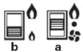
a = Slide valve Heating-Off-Ventilation
b = Slide valve for high setting (large flame symbol) low setting (small flame symbol)
Control panel with rotary switch
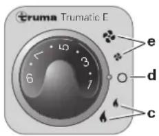
c = "Heating" rotary switch high setting (large flame symbol) low setting (small flame symbol)
d = "Off" rotary switch
e = "Ventilation" rotary switch
high setting (large symbol)
low setting (small symbol)
Switching on the Heating
- Remove cowl cap.
- Turn on gas cylinder and open quick-acting valve in the gas supply line.
- Adjust desired room temperature at rotary knob.
- Switching the heating on:
Control panel with sliding switch
Set the switch (a) to Heating and switch (b) to the desired output setting.
Control panel with rotary switch
Set the rotary switch to the desired output setting (c).
If the outside temperature is low, switch to high setting.
The Trumatic E heater has been tested and approved for operation, also when the vehicle is moving. The burner with fan assistance guarantees satisfactory operation, even under extremely windy conditions. It may be necessary to observe respective, country-specific regulations for the operation of liquid gas appliances when the vehicle is moving.
Switching on the Ventilation
Control panel with sliding switch
Set switch (a) to Ventilation and switch (b) to the desired output setting.
Control panel with rotary switch
Set the rotary switch to the desired output setting (e).
Switching off
Set the sliding switch (a) or the rotary switch (d) to the centre. If the appliance is switched off after a heating phase, the fan can continue running in order to make use of the residual heat.
If the appliance is not used for a prolonged period of time, close quick-acting valve in the gas supply line and turn off gas cylinder.
Green LED "Operating"
(under rotary control knob)
When the device is switched on (heating or ventilation), the green LED must light up (the fan is operational). If the LED does not shine, check the (main) switch. For this purpose observe respective instructions of the vehicle manufacturer.
During the heating process whilst the flame is burning, the green LED shines twice as brightly. This also makes it possible to determine the instantaneous switching point of the room temperature.
Fuses
The device and control panel fuses are on the electronic control unit on the device.
Device fuse (F1):
$$ 3. 1 5 \mathrm {A T} - \text {s l o w} - (\mathrm {E N} 6 0 1 2 7 - 2 - 3) $$
Control panel fuse (F3):
1.6 AT - slow -
The fine-wire fuse must only be replaced by a fuse of the same design.
Red LED "Failure"
In the event of a failure, the red LED shines. Possible causes for the failure can be e.g. no gas, insufficient combustion air, heavily soiled rotor, defective fuse etc.. Deactivate by switching off and then switching on again.
Opening a window to which a window switch is attached and closing it again is the equivalent of switching the equipment off and on again at the control panel (e.g. a fault reset)!
Flash operation indicates that the operating voltage is too low or too high for the appliance (charge battery, if necessary).
In Germany, always notify the Truma Service Centre if problems are encountered; in other countries the relevant service partners should be contacted (see Truma Service Booklet or www.truma.com).
Disposal
The device must be disposed of in line with the administrative regulations of the respective country in which it is used. National regulations and laws (in Germany, for example, the End-of-life Vehicle Regulation) must be observed.
Accessories
1. Control unit VG 2
for heaters of driver's cabs in tank vehicles, for the transportation of hazardous goods according to ADR (not to be used in combination with a time switch).
2. Outside switch AS
for switching the heater on and off from the outside of the vehicle, e.g. for cargo space heaters (available with 4m or 10m connecting cables).
3. Acoustic signalling device ASM
gives an acoustic signal in event of a failure.
4. Time switch ZUE / ZUE 2
for pre-programming 3 switch-on times within 7 days, including 4m connecting cable (suitable for 12V and 24V vehicle electrical system).
ZUE, part no. 39890-00, for installation in existing cut-outs, suitable for control panel with slide switch.
ZUE 2, part no. 39891-00 with cover frame, suitable for control panel with rotary switch.
5. Remote sensor
monitors the room tem perature independent of the position of the control panel (available with 4m or 10m connecting cable).
6. Multiple connector MSD
for connecting several accessories (e.g. time switch and remote sensor).
Extension cable for accessories
items 1-6 of 4m or 10m (not illustrated).
7. Direct switch DIS 1
for operating the heater at high setting only, without temperature control (available with 10m connecting cable). Replaces control panel.
Or direct fixed temperature switch DFS
for operating the heater at a fixed temperature (40^ - 70^ depending on the version). Replaces the control panel.
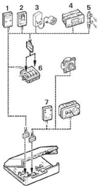
All electrical accessories are fitted with a connector and can be connected individually.
Technical data
determined in accordance with EN 624 or Truma test conditions
Type of gas
Liquid gas (propane / butane)
Operating pressure
30 mbar (see type plate)
Rated thermal output
High setting: 2400 W
Low setting: 1200 W
Gas consumption
High setting: 200g / h
Low setting: 100g / h
Air flow rate
High setting: approx. 78m^3/h
Low setting: approx. 49m^3/h
Current input at 12V
High setting: 1.1 A
Low setting: 0.6 A
Current input at 24V
High setting: 0.7 A
Low setting: 0.4 A
Standby
0.01 A
Weight
Heater unit: 4.8kg
Heater unit with peripheral devices: 5.1kg

0085
The right to effect technical modifications is reserved!
Dimensions
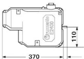
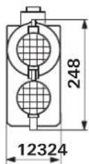
All dimensions in mm.
Trouble-shooting list
| Fault Cause Rectification | ||
| After switching on none of the LEDs are lit. | - No operating voltage. | Check 12 V / 24 V battery voltage, charge if necessary. - Check all electrical plug connections. |
| - Device fuse or vehicle fuse defective. | - Check the unit or vehicle fuse and replace if necessary (see fuses). | |
| The green LED comes on when the unit is switched on but the heater does not operate. | - Select high temperature at the control panel.- the control panel is lower than the room temperature. | |
| - Open window above cowl (window switch). | - Close window. | |
| Red LED flashes 1 x per sec. | - Under-voltage range 12 V: 10.9 V - 10.5 V. 24 V: 21.8 V - 20.7 V | - Charge battery! |
| Red LED flashes 3 x per sec. | - Over-voltage range 12 V: 15.8 V - 16.4 V. 24 V: 31.8 V - 33.1 V | - Check the battery voltage and power supply such as e.g. the charging device. |
| Approximately 30 seconds after the heater is switched on, the red LED is lit. | - Gas cylinder or quick-closure valve in the gas line is closed. | - Check gas supply and open valves. |
| - Combustion air infeed or exhaust outlet is sealed. | - Remove cowl cap. - Inspect openings for contamination (slush, ice, leaves, etc.) and remove contamination if necessary. | |
| After operating for a longer period of time, the heater switches to failure. | - Hot-air outlets blocked. | - Check individual outlet apertures. |
| - Recirculated air intake blocked. | - Remove blockage from recirculated air intake. | |
| - Gas pressure regulator iced up. | - Use regulator heating (EisEx). | |
If this does not solve the problem, please contact the Truma Service.
Declaration of conformity
1. Information about the manufacturer
Heater/TrumaticE2400(E)
3. Meets the requirements of the following EC Directives
3.1 Gas Appliances Directive 2009/142/EC
3.2 Heating Appliance Directive 2001/56/EC, 2004/78/EC, 2006/119/EC
3.3 Radio Interference in Vehicles 72/245/EEC (with the supplements)
3.4 Electromagnetic Compatibility 2004/108/EC
3.5 End-Of-Life Vehicle Directive 2000/53/EC
and bears the type approval numbers e1 00 0144, e1 03 2605 and the CE symbol with the CE product ident. no. CE-0085AO0008.
4. Basis of the conformity assessment
EN 624, EN 298, DIN 30694-1, 2001/56/EG, 2004/78/EG, 2006/119/EG; 2004/104/EG, 2005/83/EG, 2006/28/EG; 2004/108/EG; 2000/53/EG
5. Auditing body
DVGW, Federal Motor Transport Authority
6. Information and the function of the signatory
Signature: Dr. Andreas Schmoll
Managing Director / Engineering Putzbrunn, 26.03.2010
Manufacturer's terms of warranty
1. Case of warranty
The manufacturer grants a warranty for malfunctions in the appliance which are based on material or production faults. In addition to this, the statutory warranty claims against the seller remain valid.
A claim under warranty shall not pertain
for parts subject to wear and in cases of natural wear and tear,
- as a result of using components in the units that are not original Truma parts,
for gas pressure regulation systems as a result of damage by foreign substances (e.g. oils, plasticisers) in the gas,
- as a consequence of failure to respect Truma instructions for installation and use,
- as a consequence of improper handling,
- as a consequence of improper transport packing.
2. Scope of warranty
The warranty is valid for malfunctions as stated under item 1, which occur within 24 months after conclusion of the purchase agreement between the seller and the final consumer. The manufacturers will make good such defects by subsequent fulfilment, i.e. at their discretion either by repair or replacement. In the event of manufacturers providing service under warranty, the term of the warranty shall not recommence anew with regard to the repaired or replaced parts; rather, the old warranty period shall continue to run. More extensive claims, in particular claims for compensatory damages by purchasers or third parties, shall be excluded. This does not affect the rules of the product liability law.
The manufacturer shall bear the cost of employing the Truma customer service for the removal of a malfunction under warranty - in particular transportation costs, travelling expenses, job and material costs, as long as the service is carried out in Germany. The warranty does not cover customer service work in other countries.
Additional costs based on complicated removal and installation conditions of the appliance (e.g. removal of furniture or parts of the vehicle body) do not come under warranty.
3. Raising the case of warranty
The manufacturer's address is:
Truma Geratetechnik GmbH & Co. KG
Wernher-von-Braun-Straße 12
85640 Putzbrunn, Germany
Always notify the Truma Service Centre or one of our authorised service partners if problems are encountered (see Truma Service book or www.truma.com). Please describe you complaint in detail and state the factory number of the device and the purchase date.
In order for the manufacturer to be able to determine whether an incident subject to guarantee has occurred, the end user must, at his own risk, bring or send the device to the manufacturer. If there is damage to heat exchangers, the gas pressure regulator must also be sent back to the factory.
Air conditioners:
To avoid transportation damage, the unit may only be sent to the Truma Service Centre Germany or one of our authorised service partners if agreed beforehand. Otherwise the sender bears the risk for any transportation damage.
Please send all shipment to the factory as freight. In cases under guarantee, the works shall bear the transport costs or the costs of delivery and return. If the damage is deemed not to be a warranty case, the manufacturer shall notify the customer and shall specify repair costs which shall not be borne by the manufacturer; in this case, the customer shall also bear the shipping costs.
Installation instructions
The installation and repair of the appliance is only to be carried out by an expert. Read the installation instructions carefully prior to starting work and observe the instructions!
Non-compliance with installation instructions or incorrect installation can result in endangerment of persons and property.
Intended use
This device was designed for installing in vehicles (motor homes, caravans, boats and commercial vehicles). Other applications are also possible following consul tation with Truma.
Installation inside busses (vehicle classes M2 and M3) is not permitted.
Vehicles for class EX/II and EX/III hazardous materials Combustion heaters for gaseous fuel are not permitted.
Approval
Directive 2004/78/EC stipulates that a safety shut-off device is required if motor homes are being heated while driving. The Truma gas pressure control systems SecuMotion / MonoControl CS satisfy these requirements.
The installation of a safety shut-off device, such as e.g. the gas pressure control system Truma SecuMotion / MonoControl CS with the correct gas installation configuration, means that the operation of a type-approved liquid gas heating system when the vehicle is on the move is approved throughout Europe in accordance with the EC Directive 2001/56/EC.
The safety shut-off device is also recommended for safety reasons if caravans are being heated while driving.
The heater is approved for installation in motor vehicles for transporting passengers (motor caravans in vehicle class M1) that have no more than 8 seats excluding the driver's seat, for trailers (caravans in vehicle class O) and for commercial vehicles (vehicle class N).
The year when the equipment was first taken into operation must be indicated with a check on the type plate.
Regulations
Guarantee claims, warranty claims and acceptance of liability will be ruled out in the event of the following:
modifications to the unit (including accessories),
modifications to the exhaust duct and the cowl,
- failure to use original Truma parts as replacement parts and accessories,
- failure to follow the installation and operating instructions.
It also becomes illegal to use the appliance, and in some countries this even makes it illegal to use the vehicle.
In-vehicle installations must comply with the technical and administrative regulations of the respective country of use (e.g. EN 1949 for vehicles). The national regulations and rules (e.g. DVGW work sheet G 607 in Germany) must be complied with.
The relevant employer's liability insurance association accident prevention regulations must be observed in Germany for vehicles used for commercial purposes (BGV D 34).
In other countries always observe the respectively valid regulations.
For further details on the rules and regulations in the respective country of desig-nation, please contact our agencies abroad (see Truma Service Booklet or www.truma.com).
Notes on the installation in commercial vehicles
The TUV-tested cylinder holder (part no. 39742-00) is a constituent of the type approval for Trumatic E heaters in accordance with heater directive 2001/56/EC. Here it is stated that 2 gas cylinders with a contents of max. 15kg can be connected and used for operating the heaters while the vehicle is moving. For the protection of the cylinder valve and the gas pressure regulator, just the protective cover provided with the cylinder bracket is required.
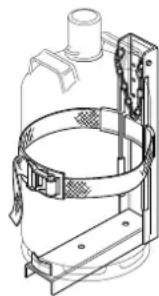
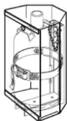
For protection against theft or for reasons of appearance, the gas cylinder can also be concealed using the lockable cylinder cabinet (part no. 39010-21100). The cabinet is bolted with the cylinder bracket to the vehicle frame.
When installing the heater in special vehicles (e.g. vehicles for transporting hazardous goods), the respective regulations for such vehicles must be observed.
Notes on installation in driver's cab
In the case of heating systems where the waste gas is guided below the vehicle floor, the waste gas cowl outlet must be attached up to the side or rear edge of the driver's cab or the vehicle. Steps must be taken to ensure that no waste gases can enter the inside of the vehicle (e.g. from below through the vehicle floor).
Model-related assembly instructions can be obtained from Truma.
In Germany, for tank vehicles carrying hazardous goods in the field of application covered by the ADR, the appliance is only approved with the Truma control unit.
Notes on installation in boats
Installation in boats must accord with the technical and administrative provisions of the individual country of use (e.g. EN ISO 10239 for boats). National specifications and regulations (in Germany, for example, DVGW Worksheet G 608) must be respected.
The "Guidelines for the Construction, Installation, Testing and Operation of Liquid Gas Systems for Household Purposes on Inland Waterways" (BGR 146) must be complied with in Germany. According to these guidelines the liquid gas system must be installed by an engineer who has been approved by the inland waterways employer's liability associations and tested by experts belonging to these employer's liability insurance associations.
In other countries always observe the respectively valid regulations.
For further notes on installation, refer to the assembly instructions for the Trumatic E boat heater.
Choice of location
Always install the appliance and its exhaust duct in such a way that it is always easily accessible for service work and can be removed and installed easily.
For evenly distributed heating, the installation of the appliance should be as much in the centre of the vehicle as possible (or under the vehicle), and in such a way that the air distribution ducts can be routed with approximately the same length.
Cowls must always be fitted to prevent any waste gases entering the inside of the vehicle. The waste gas must always be guided to at least a side wall.
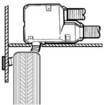
The wall cowl must be attached so that no tank supports or tank ventilation openings are found within 500mm (R). In addition, no air discharge apertures for the living area or window openings may be located with 300mm (R) of it.
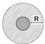
When fitting the cowl within the marked area below or next to a window that must be open, an electrical window switch (part no. 34000-85800) must be installed. The gas unit must automatically switch itself off using the Truma automatic shut-off facility if the window is opened (Accessories, part no. 39050-00800).

Exhaust duct
With the Trumatic E 2400 only use the Truma exhaust duct AA 24 (part no. 39420-00) for the installation with wall cowl, and for boats use the Truma stainless steel exhaust duct AEM 24 (part no. 39430-00) and the combustion air supply duct ZR 24 (part no. 39440-00) as the appliance has only been tested and approved with these ducts.

A new O-ring must always be installed after dismantling the exhaust duct!
Permissible duct lengths
-
Interior installation with wall cowl (refer to installation variant 1, page 2):
-
Duct lengths of up to max. 70 cm can be routed as ascending duct in any way required, or descending by max. 30 cm.
Duct lengths from 70 cm to max. 150 cm must be routed as ascending duct with an ascending angle of min. 45^ -
Under-floor assembly with wall cowl (refer to installation variant 2, page 2):
Cowl double duct length max. 70 cm, routed as ascending duct in any way required or descending by up to 30 cm.
Interior installation using the wall cowl kit
Refer to installation variant, Fig 1 (page 2).
Assembly of wall cowl
Assemble wall cowl on a surface which is as flat as possible and which is exposed to wind from all directions. Drill an opening (8) measuring 70mm in diameter (pack wood into hollow spaces in the area of the cowl opening). Use the provided rubber seal (10) for sealing. In the event of structured surfaces, coat with plastic body sealant - do not use silicone.
In the event of a greater wall thickness, first connect the exhaust double duct to the cowl from the outside.
Slide rubber seal (10) and clamp (4) onto the cowl inner part (11).
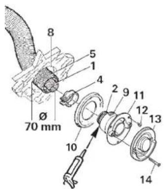
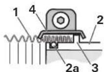
Press end of ex-haust duct (1) together so that winding touches winding, slide over the O-ring (2a) on the connection fitting (2) up to the collar (3 - cowl bend pointing upward) and tighten clamp (4) in such a way that the knurled edge of the clamp encloses the collar.
Coat serrated connection fitting (9) with plastic body sealant - do not use silicone! - and slide over combustion air supply duct (5).
Fasten cowl inner part (11) with 3 screws (12 - observe installation position! The Truma lettering must be at the bottom). Mount cowl outer part (13) and screw on with 2 screws (14).

Always install a new O-ring following any disassembly!
Fastening the appliance
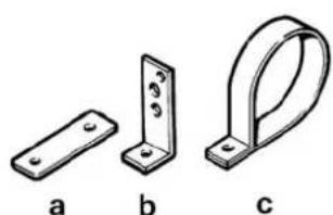
Depending on the installation position, bolt on the appliance using fastening strap (a) or mounting brackets (b). Fasten exhaust double duct to the wall using duct clamp ZR 24 (c), if necessary (parts to be found in enclosed kit).
Double cowl duct connection to the heating appliance
Press end of ex haust duct (1) together so that winding touches winding. Slide clamp (4) over exhaust duct (1). Slide exhaust duct over O-ring on the connection fitting (2) up to the collar (3). Attach with clamp (4) in such a way that the knurled edge of the clamp encloses the collar. Fasten combustion air supply duct (5) on the connection fitting (6) using clamp (7).
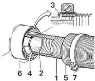

Always install a new O-ring following any disassembly!
Under-floor assembly with wall cowl kit
Refer to installation variant fig. 2 (page 2).
Install wall cowl on as flat a surface as possible on an outside wall (vehicle apron, refer to "Notes on installation in driver's cab").

If the wall cowl is fitted with fixing brackets or similar below the floor, the vehicle floor must be airtight andaste gas must always be guided up to the side wall (see using the installation place").
Fastening the appliance
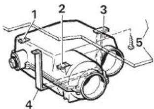
Screw the 3 fastening strips (1,2 + 3) to the appliance. Screw appliance to vehicle floor with the strips 1 + 2 .Fasten assembly bracket (4 - Accessories part.no.39050-74000) together with strip (3) and screws (5). Place lock washers under all screw heads and nuts.
Warm air distribution and circulating air return with interior installation
Warm air distribution
Hot air suction apertures must be arranged in such a way that no exhaust gases from the engine or the heating device can be drawn in. It must be ensured by means of construction design that the heating air introduced into the vehicle is not polluted (e.g. by oil vapour). This is achieved, for example, with air heaters with circulating air operation, both for interior installations and for external installations (in heaters with fresh air operation the fresh air is not to come from the engine compartment or from the vicinity of the exhaust or the exhaust outlet of the heater).
The warm air (W) is blown out from the appliance, either directly or using a warm air duct VR 80 (80 mm diameter).
Remove grating from warm air outlet of the appliance. Connect duct VR 80 (80 mm diameter). By positioning a manifold section, the ducts VR 72 (72 mm diameter), UR (65 mm diameter) or ZR 18 (49 mm diameter) can also be added on.
In order to avoid overheating, there must be at least one air passage which is always open (swivel nozzle SCW 2). Secure all duct connections with self-tapping screws. Fasten ducts with clamps.
The hot air system is individually designed for each vehicle model using a modular principle. A wide range of accessories is available for this purpose (see brochure). Diagrams with optimum installation suggestions for hot air systems in all of the most popular motor home models can be requested free of charge via the Truma service centre.
Circulating air return
The circulating air (U) is sucked back into the appliance, either directly or via a duct piece VR 80 (80 mm diameter).
- Direct intake: If the appliance is installed in a storage compartment or such, drill two holes measuring 75mm in diameter into it, or make a corresponding opening for the circulating air return.
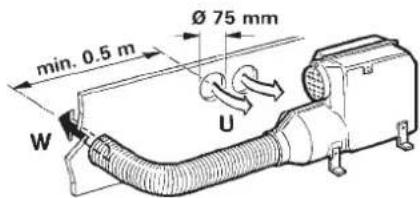

Do not obstruct the air passage to the appliance!
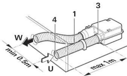
- Circulating air outside the storage area can be drawn in via a duct piece VR 80 (1) 80mm diameter (max. 1m in length) and returned to the appliance. The storage compartment can then be used to the full.
Remove protective grating from the connection fitting (3). Insert duct piece (1) into the grating connection fitting and fasten using the available screws. Attach swivel nozzle SCW 2 to the duct end (4).
Warm air supply and circulating air return with outside assembly
Refer to installation variant fig. 2 (page 2).
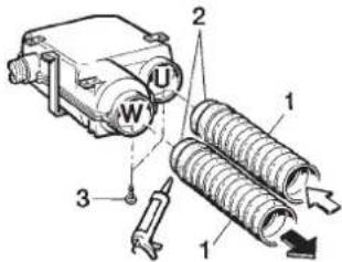
The warm air supply and the circulating air return between appliance and vehicle is provided by means of flexible air ducts LF 18 (83 mm diameter, 60 cm in length). The air ducts can be shortened as required. A protective casing over the entire heater system protects it against damage and weather conditions and simultaneously serves as insulation.
Connection of the ducts to the appliance
Remove the two protective gratings from the appliance. Coat the two pipe pieces LF 18 (1) and the rein-forced ends (2) with plastic body sealant and insert in the opening of the appliance (W + U) . Secure with two self-tapping screws (3). The duct connection must be correctly assembled, otherwise splash water can enter the appliance!
Assembly of the ducts at leadthroughs
Drill two openings 73mm diameter (W + U) . Coat the connection fittings (4) on the flange with plastic body sealant and screw on, at opening (U) place the protective grating (5) in between.
Cut the two duct pieces LF 18 (6) to the required length, if necessary, coat on the inside with plastic body sealant and slide onto the connection (4). Secure with worm drive hose clip (7).
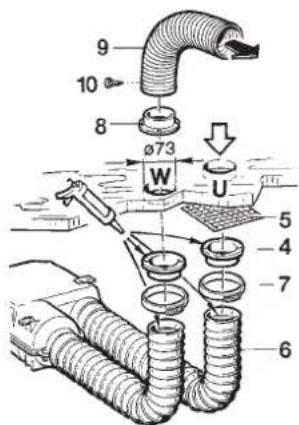
On the inside, screw on the connection fitting (8) over the opening (W - can also be screwed together with the connection fitting on the out-side). With hollow double walls make sure to seal the intermediate space.
Warm air distribution
Connect duct VR 80 (9) 80mm diameter and secure with self-tapping screw (10). The various parts for the duct branching can also be mounted on the connection fitting (8), for the further routing of the ducts VR 72 (72 mm diameter), UR (65 mm diameter) or ZR 18 (49 mm diameter).
In order to prevent overheating, at least one air passage must always be kept open (swivel nozzle SCW 2). Secure all duct connections with self-tapping screws. Fasten duct with clamp.
The hot air system is individually designed for each vehicle model using a modular principle. A wide range of accessories is available for this purpose (see brochure). Diagrams with optimum installation suggestions for hot air systems in all of the most popular motor home models can be requested free of charge via the Truma service centre.
Circulating air return
The appliance must be able to intake sufficient circulating air through the opening (U). If the circulating air return takes place inside a storage compartment, drill two holes (13) into it, each measuring 75mm in diameter or apply an appropriately sized opening.
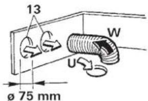
Do not obstruct air passages to the appliance!
If the storage compartment is to remain in full use, the return air can be drawn in through a swivel nozzle SCW 2 and a duct piece VR 80. For this purpose screw a connection fitting over the opening (U). Overall length up to the appliance max. 2m
Fitting the control panel
When using control panels which are specific to the vehicle or manufacturer, the electrical connection must be effected in accordance with Truma interface specifications. Any modification made to the Truma components pertaining to this will lead to the cancellation of the guarantee and to the exclusion of any claims for liability. The installer (manufacturer) is responsible for providing operating instructions for the user as well as for the labelling of the control panels!
When selecting the location, take note that the control panels must not be subjected to any direct radiant heat. Length of the connection cable 4m or 10m .
If installation is only possible behind curtains or in similar locations with temperature fluctuations, a remote sensor for the ambient temperature must be used (Accessories).
Installing the control panel with rotary switch
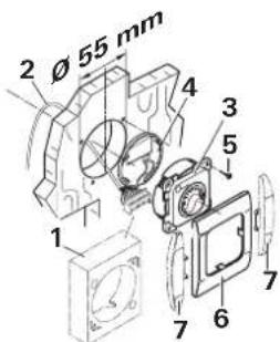
If flush mounting is not possible, Truma will supply an on-surface frame (1 - part no. 40000-52600) as an accessory on request.
Drill a hole 055mm in diameter.
Plug the control panel cable (2) into the control panel (3) and then fit the rear cover cap (4) as a stress-relieving device.
Push the cable through to the rear and lay it to the electronic control unit.
Secure the control panel with four screws (5) and fit the cover frame (6) in place.
Truma offers side parts (7) in eight different colors for finishing the cover frames (6) in a visually pleasing way. Please ask your dealer.
Installing the control panel with slide switch
For existing installation sections.
Remove the cover screen from the installation section.
Plug the control panel cable (10) into the control panel (8), feed it to the rear through the installation section, and lay it to the control panel.
Push the control panel (8) in until the front face is flush with the surface.
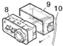
If there is no installation section present, the control panel can be fitted with the flush-fitting installation frame provided.
If flush mounting is not possible, Truma will supply an on-surface frame (part no. 39050-11600) as an accessory on request.
Fitting the electronic control unit
Unscrew the cover of the control unit.
The plug on the electronic control unit should only be withdrawn or plugged in if the supply voltage had been disconnected beforehand. Pull the plug out straight!
Insert the plug on the control panel cable (1) as shown in the diagram onto the red terminal strip of the control unit.
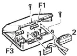
If a timer switch or a fine sensor is fitted, its plug is to be inserted on the black terminal strip. If several accessory components are being used at the same time, connection is effected via the multiple socket (Accessories).
Secure the lower part with two screws at an easily accessible location, protected against moisture (must not be heated to above 65^ ).
Screw the cover of the control unit into place.
If the appliance is assembled on the outside of the vehicle, the electronic control unit must be installed inside the vehicle, where it is protected against moisture and damage. Drill an opening of 25mm diameter in the floor or wall, disconnect connector (2) of 20-pin cable form the control unit and pass through the opening. Seal with cable grommet. Re-insert connector.
In special cases, the electronic control unit can be assembled on the outside of the vehicle, in a protective box, for the electronics on the outside (Accessories, part no. 39950-00).
Electrical connection 12 V / 24 V
Electric cables, switching units and control units for heaters must be arranged in the vehicle in such a way that their satisfactory operation cannot be adversely affected under normal operating conditions. All cables leading to the outside must be splash proof at the leadthrough opening.
Prior to working on electric components the appliance must be disconnected from the power supply. Switching off at the control panel is not sufficient!
When carrying out electric welding work on the body the appliance connection must be disconnected from the vehicle electrical system.
If the connections are transposed there is a risk of cable burning. This also rules out any guarantee or liability claims!
The red cable is positive, the blue cable is negative!
Connect the appliance to the fused vehicle electrical system (central electrical system 5 - 10 A) using the 2 × 1.5 ~mm^2 cable, for lengths over 6 ~m use 2 × 2.5 ~mm^2 cable. Negative cable to central ground. For direct connection to the battery the positive and negative cable must be fused. Connections in Faston terminals, fully insulated (motor vehicle flat connector system, 6.3 ~mm ).
Do not connect any other consumers to the supply line!
When power packs or power supply units are being used, note that the output voltage is between 11V and 15V and the alternating current ripple is < 1.2Vpp . We recommend the automatic chargers from Truma for the different applications. Please ask your dealer. Other chargers may be used only with a 12V battery as a buffer.
Gas connection
The operating pressure of the unit (30 mbar, see type plate) must be the same as the gas supply's operating pressure.
The gas supply line (8 mm dia.) must be attached to gas-connection muff with olive screw fitting. Carefully counterhold with another spanner when tightening!
The gas connecti on fitting on the appliance is not to be shortened or bent.
Prior to connecting the appliance make sure that the gas lines are free from dirt, chips and such!
Choose to route the pipes in a way that will facilitate removing the unit for service tasks.
Keep the number of parting connections in the gas supply line in rooms frequented by people to a technically feasible minimum.
The gas system must accord with the technical and administrative provisions of the individual country of use (in Europe, for example, EN 1949 for motor vehicles or EN ISO 10239 for boats). National regulations and rulings (in Germany, for example, the DVGW worksheet G 607 for motor vehicles or G 608 for boats) must be respected.
Function check
After installation, the gas feed line must be tested for tightness by the pressure-drop method. A test certificate (in Germany, for example, in accordance with DVGW Worksheet G 607 for motor vehicles or G 608 for boats) is to be issued.
All equipment functions must be tested in accordance with the user manual after installation.
The operating instructions and completed guarantee card are to be given to the owner of the vehicle.
i Remove the type plate from the operating and installation instructions and affix it at a position on the heater which is clearly visible and well protected against damage. The year of initial operation must be marked on the type plate.
Warning information
The installer or vehicle owner must apply the yellow sticker with the warning information, which is enclosed with the appliance, to a place in the vehicle where it is clearly visible to all users (e.g. on the wardrobe door)! Ask Truma to send you stickers, if necessary.
Table des matieres
Sous reserve de modifications techniques!
Dimensions
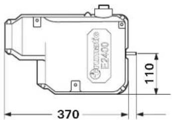
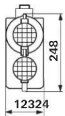
2. Identification of apparatus
Type / udforelse:
Varmeovn / Trumatic E 2400 (E)
3. Opfylder kravene i falgende EF-direktiver
3.1 Opvarmningsanlaegsdirektiv 2009/142/EF
3.2 Opvarmningsanlaegsdirektiv 2001/56/EF, 2004/78/EF, 2006/119/EF
3.3 Stjdaempning i motorkoretjer 72/245/E0F (med tillaeg)
3.4 Elektromagnetik kompatibilitet 2004/108/EF
3.5 Direktiv 2000/53/EF vedr. gamle koretoger
5. Overvågende organ
fragtGods. I garantitilfaelde overtager fabrikken transport
GB In Germany, always notify the Truma Service Centre if problems are encountered; in other countries the relevant service partners should be contacted (see Truma Service Booklet or www.truma.com).
Having the equipment model and the serial number ready (see type plate) will speed up processing.