Combi D 6 - Heating Trumatic - Free user manual and instructions
Find the device manual for free Combi D 6 Trumatic in PDF.
Frequently Asked Questions - Combi D 6 Trumatic
User questions about Combi D 6 Trumatic
0 question about this device. Answer the ones you know or ask your own.
Ask a new question about this device
Download the instructions for your Heating in PDF format for free! Find your manual Combi D 6 - Trumatic and take your electronic device back in hand. On this page are published all the documents necessary for the use of your device. Combi D 6 by Trumatic.
USER MANUAL Combi D 6 Trumatic
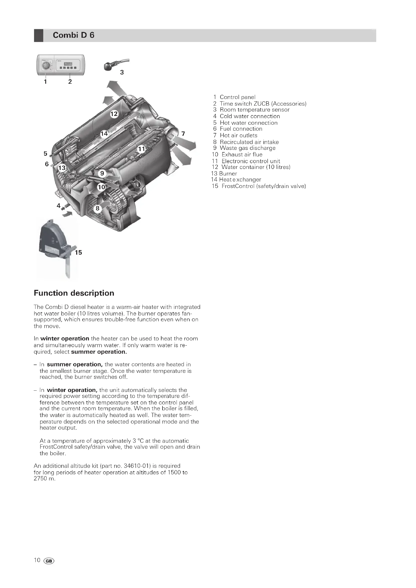
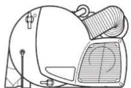
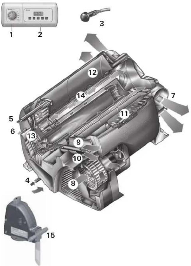
The Combi D diesel heater is a warm-air heater with integrated hot water boiler (10 litres volume). The burner operates fan-supported, which ensures trouble-free function even when on the move.
In winter operation the heater can be used to heat the room and simultaneously warm water. If only warm water is required, select summer operation.
- In summer operation, the water contents are heated in the smallest burner stage. Once the water temperature is reached, the burner switches off.
In winter operation, the unit automatically selects the required power setting according to the temperature difference between the temperature set on the control panel and the current room temperature. When the boiler is filled, the water is automatically heated as well. The water temperature depends on the selected operational mode and the heater output.
At a temperature of approximately 3^ at the automatic FrostControl safety/drain valve, the valve will open and drain the boiler.
An additional altitude kit (part no. 34610-01) is required for long periods of heater operation at altitudes of 1500 to 2750m .
1 Control panel
2 Time switch ZUCB (Accessories)
3 Room temperature sensor
4 Cold water connection
5 Hot water connection
6 Fuel connection
7 Hot air outlets
8 Recirculated air intake
9 Waste gas discharge
10 Exhaust air flue
11 Electronic control unit
12 Water container (10 litres)
13 Burner
14 Heat exchanger
15 FrostControl (safety/drain valve)
Safety instructions
In the event of a leak in the heater or the exhaust duct:
- use the rotary switch to switch off heater,
open windows and door, - ask an expert to inspect the entire system!

Repairs may only be carried out by an expert!
Guarantee claims, warranty claims and acceptance of liability will be ruled out in the event of the following:
modifications to the unit (including accessories),
modifications to the exhaust duct and the cowl,
- failure to use original Truma parts as
replacement parts and accessories.
- failure to follow the installation and operating instructions.
It also becomes illegal to use the appliance, and in some countries this even makes it illegal to use the vehicle.
During the initial operation of a brand new appliance (or after it has not been used for some time), a slight amount of fumes and smell may be noticed for a short while. It is a good idea to heat the device up several times in summer operation (60^) and to make sure that the area is well ventilated.
The system must comply with the respective regulations of the country in which it is used. National regulations and rules must be followed.
Absolutely no objects (e.g. spray cans) or flammable liquids are to be stored in the installation room or on the heater unit, since they may be exposed to increased temperature levels under certain conditions.
The exhaust system must be inspected by a qualified technician at regular intervals, not exceeding two years.
No work must be carried out on the heater, the exhaust duct or in the vicinity of the chimney while the unit is in operation.
Do not inhale exhaust fumes.
Before performing any work on the heater or the exhaust duct, switch off the heater and allow all parts to cool completely.
The heater must not be used during fuelling, or in enclosed car parks, in garages, or on ferries.
Do not operate the heater anywhere where flammable vapours or dust can form, e.g. in the vicinity of a fuel, carbon, wood or cereal storage facility or similar.
Important operating notes
If the cowl has been placed near or directly beneath an opening window, the device must be equipped with an automatic shut-off device in order to prevent operation with the window open.
The exhaust gas double duct (exhaust gas silencer and suction pipe) must be inspected regularly, particularly following long journeys, to check for any damage and to ensure that the connection is sound; the same applies to the mounting of the heater and the cowl.
The cowl and the combustion air infeed must be kept free of dirt (e.g. snow sludge, ice, foliage, etc.) at all times.
The hot air outlets and circulating / exhaust air intake openings must be unobstructed, to ensure that the heater is not at risk of overheating. The built-in temperature limiter blocks off the fuel supply when the heater becomes excessively hot.
Even outside the season, the heater should be operated once a month for about ten minutes.

When operational, the fuel display in the fuel tank must not be allowed to drop to the "low fuel" mark.
In the event that the vehicle fuel tank runs empty, the opening of the fuel removal duct is roughly at the same height as the surface of the fuel. In this state, and in particular when the fuel in the vehicle fuel tank slops around due to vehicle movement, a large amount of air is sucked in. This leads to an irregular supply of fuel to the heater. The heater burner is unable to maintain clean combustion in this condition, leading to the formation of smoke and odours.
A diesel heating system always needs more power than a similar gas heating system. If there is a requirement for an autarky of the same length (service life without external power supply), Truma recommends investigating whether it is possible to retrofit a larger and / or second battery.
Fuel supply
Fuel quality
The heater requires diesel fuel for its operation, as per DIN EN 590. Operation with biodiesel is not permitted (PME, RME or AME).
Fuel at low temperatures
The refineries and filling stations will automatically perform the required adjustments for standard winter temperatures (winter diesel).
Temperatures below 0^ can create difficulties if the vehicle still has summer diesel in its fuel tank.
If no special diesel fuel is available for use in low temperatures, e.g. winter diesel, then petroleum or benzine should be mixed in with the fuel, in accordance with the instructions given by the vehicle manufacturer.
Temperature
0°C to -20°C Winter diesel
-20 °C to -30 °C Polar or Arctic diesel
Used oil should not be used in a fuel mixture!
To guarantee that all fuel lines of the heater unit are filled with winter diesel or another permitted mixture after fuelling, the heater must be operated for at least fifteen minutes.
Operating instructions
Always observe the operating instructions and "Important operating notes" prior to starting! The vehicle owner is responsible for the correct operation of the appliance.
The installer or vehicle owner must apply the yellow sticker with the warning information, which is enclosed with the appliance, to a place in the vehicle where it is clearly visible to all users (e.g. on the wardrobe door)! Ask Truma to send you stickers, if necessary.
Before using for the first time, it is essential to flush the entire water supply system through with clean water. If the heater is not being used, always drain the water contents if there is a risk of frost! There shall be no claims under guarantee for damage caused by frost!
Materials in the device which come into contact with water are suitable for use with drinking water (see manufacturer declaration: www.truma.com - Downloads - Manufacturer Declaration).
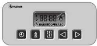
Control panel
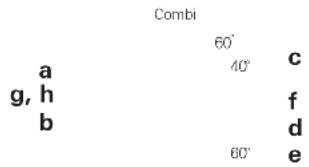
a = Rotary switch for room temperature (1 - 5)
b = green LED lit "Operation"
green LED blinking
after-running" is active in order to reduce the unit's temperature
c = Summer operation
(water temperature 40^ or 60^)
d = Winter operation
(heating without water temperature monitoring
or with drained water system)
e = Winter operation
(heating with water temperature monitoring)
f = Rotary "Off" switch
g = yellow LED lit "Boiler heat-up phase"
yellow LED flashes "failure"
h = red LED lit, red LED blinking "failure"
The LEDs are visible only when the unit is switched on.
Room thermostat
To measure the room temperature, an external room temperature sensor (i) is located in the vehicle. The location of the sensor is determined individually by the vehicle manufacturer, depending on the vehicle type; consult the operating instructions for your vehicle for further details.
i
i = Room temperature sensor
The thermostat setting on the control panel (1 - 5) must be determined individually depending on the heating requirement and the type of vehicle. For an average room temperature of about 23^ , we recommend a thermostat setting of about 4.
FrostControl
(safety/drain valve)
FrostControl is a currentless safety/drain valve. When there is a danger of frost, it automatically drains the contents of the boiler through a drainage muff. If excessive pressure is present in the system, pressure will be automatically intermittently equalized through the pressure relief valve.
k
n
m
0
k = rotary switch position "Operation"
m = push button position "Closed"
n = push button position "Drain"
o = drainage muff
(led outside through floor of vehicle)
Closing the drain valve
Check if the rotary switch is set to "Operation" (position k), meaning that it is parallel to the water connection and engaged.
Close the drain valve by activating the push button. The push button must engage in position (m) "closed".
Only when the temperature around the drain valve is over around 7^ can it to be closed manually with the press button ("m" position) and the boiler filled.
Truma supplies a heating element (part no. 70070-01) as an accessory, which is inserted into the FrostControl and fixed in place with a retaining bracket. This heating element heats the FrostControl to approx. 10^ when the Combi is switched on. This means that the boiler can be filled after a shorter time, irrespective of the temperature in the installation compartment.
Automatic opening of the drain valve
If the temperature around the drain valve is below about 3^ it will open automatically and the push button will disengage (outward movement) ("n" position). The water from the boiler will be released through the drainage muff (o).
Manual opening of the drain valve
Turn the rotary switch by 180^ until it engages, whereby the push button moves out (position n). The water in the boiler drains out through the drainage muff (o).
The FrostControl drainage muff (o) must be free of contamination (slush, ice, leaves, etc.) at all times so the water can drain out easily! There shall be no claims under guarantee for damage caused by frost!
Initial start-up
(or when the fuel tank has run empty)
Filling the fuel lines
The heater normally has to be started up several times to fill the fuel lines if an automatic filling unit is not being used.
Connect unit to control panel to do this. The unit automatically performs 2 start attempts (initial start and repeat) per switch-on procedure with a run time of 2 minutes in each case. If no flame is detected after the repeat start, the unit switches to fault and has to be switched off and on again at the control panel.
After a total of 15 unsuccessful starting attempts (initial and repeat start) without forming a flame, the equipment is blocked. To remove the block, please contact the Truma Service Centre (see Service Booklet or www.truma.com).
Check fuel lines and connections for leaks after filling the fuel lines.
Taking into operation
Heating operation is basically possible without restriction with or without water content.
Check to make sure the cowl is unobstructed. Remove any covers that may be present.
Summer operation
(boiler operation only)
Move the rotary switch on the control panel to position (c - summer operation) 40^ or 60^ . The green (b) and yellow (g) LEDs light up.
After reaching the set water temperature (40^ or 60^) the burner will switch off and the yellow LED (g) will be extinguished.
Winter operation
Heating with water temperature monitoring
Set the rotary switch to the operational setting "e".
Set the rotary switch (a) to the desired thermostat setting (1 - 5). The green LED (b) for operation is lit and simultaneously indicates the position of the selected room temperature. The yellow LED (g) indicates the water's heat-up phase.
The unit automatically selects the required power level according to the temperature difference between the setting on the control panel and the current room temperature. Once the room temperature set on the control panel has been reached, the burner switches back to the lowest stage, and heats the water content to 60^ . The yellow LED (g) will be extinguished after the water temperature is reached.
The warm air fan can continue to run in order to cool the unit (after-run).
Heating without water temperature monitoring
Set the rotary switch to the operational setting "d".
Turn the rotary switch (a) to the desired thermostat setting (1 - 5). The green LED (b) for operation is lit and simultaneously indicates the position of the selected room temperature. The yellow LED (g - water's heat-up phase) will be lit only when the water temperature is below 5^
The unit automatically selects the required power level according to the temperature difference between the setting on the control panel and the current room temperature. After reaching the room temperature set on the control panel, the burner will switch off. The warm-air fan will continue to run at a low speed as long as the blow-out temperature (on the unit) is higher than 40^ .
If the boiler is filled, the water will automatically be heated at the same time. The water temperature is then dependent on the heating output being given off, and the duration of heating required to reach the desired room temperature.
Heating with drained water system
Set the rotary switch to the operational setting "d".
Turn the rotary switch (a) to the desired thermostat setting (1 - 5). The green LED (b) for operation is lit and simultaneously indicates the position of the selected room temperature. The yellow LED (g) will be lit only when the temperature of the unit is below 5^
The unit automatically selects the required power level according to the temperature difference between the setting on the control panel and the current room temperature. After reaching the room temperature set on the control panel, the burner will switch off.
Switching off
Use the rotary switch to switch off heater (position f). The green LED (b) goes off.
If the green LED (b) blinks after switching off, then the unit's after-running is active in order to reduce the unit's temperature. This will end after a few minutes and the green LED (b) will go off.
Always drain water contents if there is a risk of frost!
Red / yellow LED "failure"
A failure is indicated when the red LED (h) shines or when the red (h) or yellow LED (g) flashes.
Please consult the Trouble-Shooting list for possible causes.
A reset (fault reset) is carried out by switching off, waiting until all LED's on the control panel have stopped flashing, and then switching the heater on again.
If the window, to which a window switch is mounted, is opened, the heating device stops operating and the yellow LED (g) flashes 3 times. The heater continues operating when the window is closed.
Filling the water heater
Check if the rotary switch for the drain valve (FrostControl) is set to "Operation", meaning that it is parallel to the water connection and engaged.
Close the drain valve by pushing the push button until it engages.
When the temperature at FrostControl is below about 7^ , first switch on the heater to warm the installation compartment and FrostControl. After a few minutes, if the temperature around the FrostControl is more than about 7^ the drain valve can be closed.
Switch on the power for the water pump (either by the main switch or the pump switch).
Open hot water taps in kitchen and bathroom, (set preselecting mixing taps or single-lever fittings to "hot"). Leave the fittings open for as long as it takes for the boiler to displace the air and fill up, and the water to flow without interruption.
If only the cold water system is operated, without the boiler, the boiler still fills with water. To avoid frost damage, the boiler must be drained through the drain valve, even if it was not operated.
When connecting to a central water supply (rural or city mains), a pressure reduction valve must always be installed to prevent pressures above 2.8 bar from developing in the water heater.
Draining the water heater
Switch off the power for the water pump (either by the main switch or the pump switch).
Open hot water taps in kitchen and bathroom.
Turn the rotary switch on the drain valve (FrostControl) by 180^ until it engages, whereby the push button moves out and the drain valve opens.
The boiler is now drained directly to the outside via the drain valve. Place a bucket beneath the outlet to check whether the water content has completely drained away (10 litres). There shall be no claims under guarantee for damage caused by frost!
Maintenance
Only original Truma parts may be used for maintenance and repair work.
Biofilm, deposits and limescale must be removed using chemicals to protect the unit from infestation by microorganisms. Only chloride-free products must be used in order to prevent damage to the unit.
The effectiveness of the use of chemicals to combat microorganisms in the unit can be increased by heating the water in the boiler to 70^ at regular intervals.
To do this, turn the rotary switch on the control panel to the 60^ (c - summer mode) position. The green (b) and yellow (g) LEDs light up.
Once the water in the boiler has reached a temperature of 60^ , the burner will switch off and the yellow LED (g) will go out. The unit must stay switched on for at least 30 minutes and no warm water may be removed. The residual heat in the heat exchanger will heat the water up to 70^ .
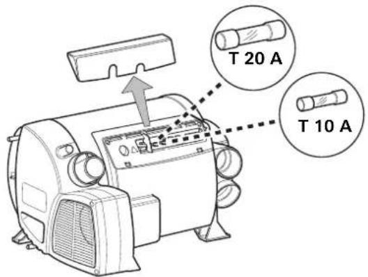
Fuses
The fuses are located in the electronic control unit, beneath the connector cover. When replacing a fuse, be sure to use the same type.
Device fuse: 10 A - slow - (T 10 A)
Burner fuse: 20 A - slow - 6.3 x 32 mm
Disposal
The heater unit must be disposed of in accordance with the administrative regulations of the country in which it is in use. National regulations and laws (in Germany, for example, the Altfahrzeug-Verordnung [old vehicle directive]) must be observed.
In other countries, the relevant regulations must be observed.
Technical data
found by Truma Test conditions
Fuel
Diesel as per EN 590
Water contents
10 litres
Heating up time from approx. 15^ to approx. 60^
Boiler approx. 20 minutes (measured according to EN 15033)
Heater + boiler approx. 80 min.
Water pressure
max. 2.8 bar
Rated thermal output (automatic output levels)
2000/4000/6000W
Fuel consumption
220 - 630 ml/h (in regular operation, between "Off" and "lowest operating level" less than 190 ml/h).
Air delivery volume (free-blowing without hot-air pipe) max. 287 m³/h
Current input at 12V
Heater + boiler 1.8 - 7 A (in regular operation, between "Off" and "lowest operating level" less than 1.8 A).
Heating boiler without operational heater, max. 1.8 A
Stand-by: approx. 0.001 A
Heating element FrostControl (optional): max. 0.4 A
Weight (not containing water)
Heater unit: 15.8kg
Heater unit with peripheral devices: 17.2kg
Declaration of conformity
The device satisfies the requirements of the following EC Directives:
Heating Equipment Directive 2001/56/EC, 2004/78/EC, 2006/119/EC
Type approval number e1 00 0232
- Noise Suppression in Vehicles 2004/104/EC, 2005/83/EC, 2006/28/EC
Type approval number e1 03 5277
End-of-Life Vehicle Directive 2000/53/EC
- Drinking Water Directive 98/83/EEC
Heating Equipment Directive UN ECE R122
Type approval number E1 122R 000232
- Noise Suppression in Vehicles UN ECE R10
Type approval number E1 10R 035277
The right to effect technical modifications is reserved!
Dimensions
450mm
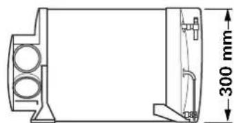
525 mm
Trouble-shooting list
Flash code on the control panel
Flash sequence LED:
- On: 0,5 seconds
-Off:0,5 seconds
Pause between the flashing sequence: 3 seconds
| Fault | Cause | Rectification | |
| After switching on (winter and summer operation) none of the LEDs are lit. | - No operating voltage. | - Check 12 V battery voltage, charge if necessary. | |
| - Check all electrical plug connections. | |||
| - Device fuse or vehicle fuse defective. | - Check the unit or vehicle fuse and replace if necessary (see fuses). | ||
| The green LED comes on when the unit is switched on, but the heater does not operate. | - The temperature setting on the control panel is lower than the room temperature. | - Select higher room temperature at the control panel. | |
| Green LED flashes after heater is switched off. | - After-running is active in order to reduce the unit's temperature. | - No error. Coasting operation switches off after max. 5 minutes. | |
| Red LED flashes 6 x. - Insufficient fuel due to insufficient fuelling, empty tank, and / or inclined vehicle orientation. | - Fill tank with fuel. Then fill the fuel line as described under "Initial start-up". | ||
| Red LED flashes (except 6 times) or red LED shines. | - Malfunction of the heating device. | - Please contact the Truma Service Centre. | |
| Yellow LED flashes 1 x. - Possible under-voltage < 11.5 V. | - Use the electrical power from the battery carefully, e.g. restrict lighting. | ||
| - Charge battery. | |||
| Yellow LED flashes 2 x. - Under-voltage < 10.2 V. - Check battery voltage, charge if necessary. | - Short-term immediate measure: switch off heavy load or start up vehicle engine until the heater starts running (approx. 4 minutes). | ||
| - Battery capacity inadequate, if necessary exchange old battery. | |||
| - Over-voltage > 16.4 V. - Check the battery voltage and power supply such as e.g. the charging device. | |||
| Yellow LED flashes 3 x. | - Open window above cowl (window switch). | - Close window. | |
| Yellow LED flashes 4 x. | - Warm air temperature and / or water temperature exceeded: | ||
| - Not all warm air ducts are connected. | - Check whether the 4 warm air ducts are connected. | ||
| - Hot-air outlets blocked. | - Check individual outlet apertures. | ||
| - Recirculated air intake blocked. | - Remove blockage from recirculated air intake. | ||
| - Summer operation with empty water tank. | - Fill boiler with water. | ||
| Yellow LED flashes 5 x. - Room temperature sensor or cable defective. | - Please contact the Truma Service Centre. | ||
| Yellow LED flashes 6 x. Water temperature exceeded in summer mode. | - Fill boiler with water. | ||
| Yellow LED flashes 7 x. - Control panel or control panel cable defective. | - Please contact the Truma Service Centre. | ||
| Yellow LED flashes 8 x. - Heating element for FrostControl has short-circuited. | - Disconnect the heating element plug on the electronic control unit. Exchange the heating element. | ||
| Water supply | |||
| After the heater is switched off, the drain valve opens (FrostControl). | - Temperature at drain valve less than approx. 3 °C. | - Switch the heater on. If the temperature is below approximately 3 °C, the drain valve will open automatically! If the heater is not in operation, the drain valve can be reclosed only when the temperature is approximately 7 °C or higher! | |
| - Use heating element for FrostControl. | |||
| The drain valve (FrostControl) can no longer be closed. | - Temperature at drain valve is below approximately 7 °C. | - Switch the heater on. If the heater is not in operation, the drain valve can be reclosed only when the temperature is approximately 7 °C or higher! | |
| - Rotary switch is not at "Operation". | - Turn the drain valve's rotary switch to "Operation", then press the push button until it engages. | ||
| Water flows intermittently from the FrostControl drain muff. | - Water pressure too high. - Check pump pressure (max. 2.8 bar). If connected to a central water supply (rural or urban connection), a pressure reducer must be used, which will prevent pressures higher than 2.8 bar entering the boiler. | ||
If these measures do not remove the failure, please contact the Truma Service Centre.
Accessories
Truma Timer ZUCB complete with 3 m connecting cable (part no. 34043-01). 6 m extension cable for time switch ZUCB (part no. 34301-03).
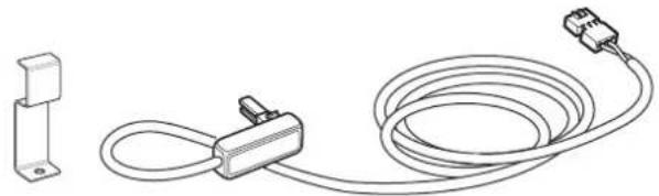
Heating element for FrostControl with 1.5m connection cable and retaining bracket (part no. 70070-01).
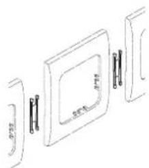
As standard, Truma supplies a suitable cover frame, in agate grey colour, for every control panel / every time switch. In addition, cover frames are also available as special accessories in the colours black, beige, platinum or gold.
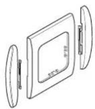
Suitable for control panels or time switches, the side pieces available in eight different colours create a visually attractive finish.
Please contact your specialist dealer in this connection.
Line-up clip, 1 unit (part no. 34000-65900). For installing several Truma control panels next to each other.
Other accessories (without picture) for control panel:
- 6 m control panel cable (part no. 34020-21400)
coupling (part no. 34020-21500) - 3 m extension cable, including coupling (part no. 34301-02)
- 6 m extension cable, including coupling (part no. 34301-01)
Manufacturer's terms of warranty
1. Case of warranty
The manufacturer grants a warranty for malfunctions in the appliance which are based on material or production faults. In addition to this, the statutory warranty claims against the seller remain valid.
A claim under warranty shall not pertain:
- for parts subject to wear and in cases of natural wear and tear,
- as a result of using components in the units that are not original Truma parts,
- as a consequence of failure to respect Truma instructions for installation and use,
- as a consequence of improper handling,
- as a consequence of improper transport packing.
2. Scope of warranty
The warranty is valid for malfunctions as stated under item 1, which occur within 24 months after conclusion of the purchase agreement between the seller and the final consumer. The manufacturers will make good such defects by subsequent fulfilment, i.e. at their discretion either by repair or replacement. In the event of manufacturers providing service under warranty, the term of the warranty shall not re commence anew with regard to the repaired or replaced parts; rather, the old warranty period shall continue to run. More extensive claims, in particular claims for compensatory damages by purchasers or third parties, shall be excluded. This does not affect the rules of the product liability law.
The manufacturer shall bear the cost of employing the Truma customer service for the removal of a malfunction under warranty - in particular transportation costs, travelling expenses, job and material costs, as long as the service is carried out in Germany. The warranty does not cover customer service work in other countries.
Additional costs based on complicated removal and installation conditions of the appliance (e.g. removal of furniture or parts of the vehicle body) do not come under warranty.
3. Raising the case of warranty
The manufacturer's address is:
Truma Geratetechnik GmbH & Co. KG,
Wernher-von-Braun Strasse 12,
85640 Putzbrunn.
In Germany, always notify the Truma Service Centre if problems are encountered; in other countries the relevant service partners should be contacted (see Truma Service Booklet or www.truma.com). Any complaints are to be described in detail. In addition, the properly completed guarantee certificate is to be presented, or the factory number of the unit and the date of purchase given.
In order for the manufacturers to be able to determine whether an incident subject to guarantee has occurred, the end user must, at his own risk, bring the device to the manufacturers or send it to them.
In instances of the device being sent to the works, dispatch is to be effected by freight transport. In cases under guarantee, the works shall bear the transport costs or the costs of delivery and return. If the damage is deemed not to be a warranty case, the manufacturer shall notify the customer and shall specify repair costs which shall not be borne by the manufacturer; in this case, the customer shall also bear the shipping costs.
Gasolio conf. EN 590
Capacità
10 litr
GB In Germany, always notify the Truma Service Centre if problems are encountered; in other countries the relevant service partners should be contacted (see Truma Service Booklet or www.truma.com).
Having the equipment model and the serial number ready (see type plate) will speed up processing.