
GT5UC6 - Boiler GORENJE - Free user manual and instructions
Find the device manual for free GT5UC6 GORENJE in PDF.

| Product type | Electric instantaneous water heater |
| Available models | GT 5 O (above sink) and GT 5 U (under sink) |
| Tank volume | 5 liters |
| Nominal pressure | 0.6 MPa |
| Weight empty / full | 7 kg / 12 kg |
| Anti-corrosion protection | Enamel coating and magnesium anode |
| Electric power | 2000 W |
| Supply voltage | 230 V ~ |
| Heating time to 75 °C | 11 minutes |
| Mixed water quantity at 40 °C | 9 liters |
| Energy consumption (maintenance at 65 °C) | 0.25 kWh/24h |
| Adjustable temperature | From 25 °C to 75 °C (economy preset at 55 °C) |
| Connection systems | Open circuit (gravity) or closed circuit (pressure) |
| Safety | Safety valve, non-return valve, bimetallic fuse |
| Regular maintenance | Descaling and inspection by authorized after-sales service every 2 years |
| Exterior cleaning | Water with a little detergent, avoid aggressive products |
| Freeze protection | Keep powered with thermostat on "*" position (approx. 9 °C) or drain if risk of frost |
| Installation | By a qualified installer, in a frost-free room |
Frequently Asked Questions - GT5UC6 GORENJE
User questions about GT5UC6 GORENJE
0 question about this device. Answer the ones you know or ask your own.
Ask a new question about this device
Download the instructions for your Boiler in PDF format for free! Find your manual GT5UC6 - GORENJE and take your electronic device back in hand. On this page are published all the documents necessary for the use of your device. GT5UC6 by GORENJE.
USER MANUAL GT5UC6 GORENJE
Instructions for Use 16
Upute za upotrebu 20
Návod k obsslze 24
Hncpykun 3a ynoTpe6a 28
HcnoHHeHnHaD yMbBaBbHkOM

HcnoJIHeHne noyMbIbAlbHnKOM HcnoJIHeHne noyMbIbAlbHnKOM
JereHda:
c) KpbIiKy KHONK 2 BHOBb BCTaBnTb Ha KOpNyc KHOHKN.
Pa6oty 3nEeKtpnueckoro HArpeBaTeIa NOKa3bIBaET KOHTpOJIbHa JAmNoUka, KOTopA rOpNT NOKa BODa B HarpeBaTeIe He corpeetcdo BBioBpaHHoTemnpaTypbl
HIN Do BbIKNoueHn. EcnB OdoHaRpeBaTeIb He 6ydeTe ynoTpeBn TaOJIe BpeM, IpeDOTBpaTIne 3aMOpoxKnBaHne BoIb TaKIM o6pa3OM TaKMn o6pa3OM, YTO erO He OTKIOUHTe OT 3JeKTPOcETn, a pykY TepMOCTata UCTAHOBnTE B NOIOKeHne *". PnN eTOn HAcTPOJKe 6yDet HaRpeBaTeIb NODepKnBaTb TemNepatypy BoIb Pn nPn6bl. 9^ . EcnO tKIOUHTe HaRpeBaTeIb OT 3JeKTPocETn, To Tpe6yEtCBA Body BCNEdCTBne ONaCHOCTN 3aMOpoxKnBaHHa BblNTb. ChapxN uNCTIne HaRpeBaTeIb paCTBOPom CTnpalbHoro nopouka. He npImeHnTpe Pa36BnteHn rpy6bie cpeCTBa dnnuCTKN.
Perynpho pemontno npOBepko oecneuhte 63ynpuehyo paobTy n doJtn cpoK clyk6bI BDOHaRpeBaTeJI. NepbyIO npOBepky dOJXHa CdeJatb yNOHOMOeHHa peMOHTa RcJx6a np6n3ntelbHO Dba rOda nocLe noKluoyehn. Ppr npOBepKe npOBepit n3HOweHHOCtB aHTNKopp03nHO 3aunTbI I NO Heo6XODMocTH OuchTt BODHO KAMHe, KOtOpBb B 3aBNCIMOCtN OT KaueCTBa, KOInueCTBa N Tempeatypbl yNOTpe6JeHHo BDoI HAKONITcB BO BHyTPEHNOCTn HarpeBaTeJI. PemOHHa Cny6a 6ydtOTHOCTeHbO YCTaHOBJEHORO COCTOHNPOE KOHTpOra HarpeBaTeJI peKOMeHDoBaTb TaKke DaTy CNeDyUoJero KOHTpOra.
ПрсимВас, He Исправлгь BO3MOЖьie NOВpeжденья Ha BOДОharpeBaTeJIe, a HIX yBeДOMHTe yNOLHOMOчeHHyо peMOHTHyO cIyнбу.
Dear customer, we thank you for purchasing our product.
PLEASE READ THE INSTRUCTIONS THOROUGHLY PRIOR TO THE INSTALLATION AND FIRST OPERATION OF THE WATER HEATER
THIS APPLIANCE IS NOT INTENDED FOR USE BY PERSONS (INCLUDING CHILDREN) WITH REDUCED PHYSICAL, SENSORY OR MENTAL CAPABILITIES, OR LACK OF EXPERIENCE AND KNOWLEDGE, UNLESS THEY HAVE BEEN GIVEN SUPERVISION OR INSTRUCTION CONCERNING USE OF THE APPLIANCE BY PERSON RESPONSIBLE FOR THEIR SAFETY.
CHILDREN SHOULD BE SUPERVISED TO ENSURE THAT THEY DO NOT PLAY WITH THE APPLIANCE.
This water heater has been manufactured in compliance with the relevant standards and tested by the relevant authorities as indicated by the Safety Certificate and the Electromagnetic Compatibility Certificate. Its basic technical properties are stated upon the nameplate, glued between the connection pipes. The water heater may be connected to water and electric power supply only by a qualified specialist. The reach in its inside due to the repair or removal of limestone and checking and replacement of anti-corrosion protection anode may be performed only by an authorised service workshop.
INSTALLATION
The water heater should be installed in a room protected from the onset of freezing conditions and located as close as possible to the points of use. Given your particular requirements there are several models of heaters to choose from: GT 5 O are suitable for installation above the basin/sink, while GT 5 U may be installed below the basin/sink.
TECHNICAL CHARACTERISTICS
| Type GT5O GT5U | ||
| Nominal capacity [ I ] 5 | ||
| Nominal pressure [ MPa ] 0,6 | ||
| Mass / filled with water [ kg ] 7/12 | ||
| Anticorrosion protection of the tank Enamelled | / Mg anode | |
| Nominal power [ W ] 2000 | ||
| Nominal voltage [ V ~] | 230 | |
| Heating time to 75°C 1) [ min ] | 11 | |
| Quantity of mixed water at 40°C [ I ] 9 | ||
| Power consumption 2) [ kWh/24h ] | 0,25 | |
1) Time required for the electrical heating element to heat the entire tank volume, at the water supply temperature of 10^ .
2) Power consumption required for the temperature of water in the water heater to be maintained at 65^ , at the room temperature of 20^ , determined in accordance with the DIN 44532 standard.
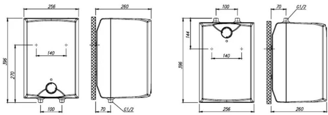
Dimensions of the water heater for installation and connection [mm]

Installation above the basin/sink Installation below the basin/sink
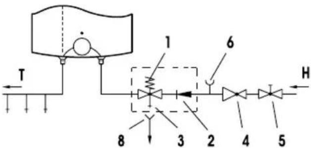
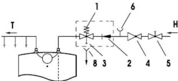
CONNECTION TO THE WATER SUPPLY
Inlet and outlet of water are on the water heater pipes marked with colour. The supply of cold water is marked with blue, the outlet of warm water is marked with red.
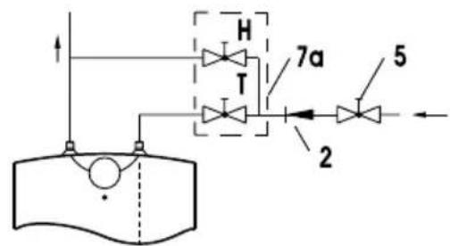
The water heater can be connected to the water supply in two manners. Closed pressure system of connection enables the outlet of water on several outlet spots, non-pressure system enables only one outlet point. With regard to the system of connection chosen, also the suitable mixing taps must be purchased.
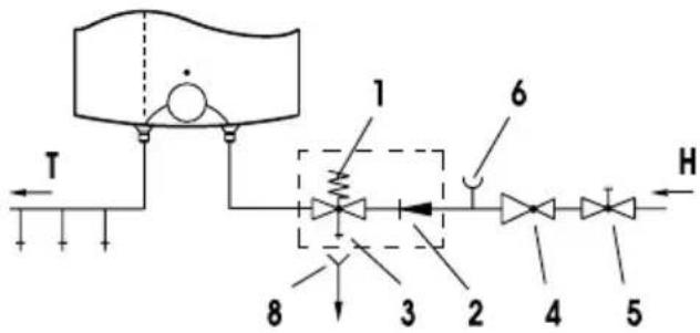
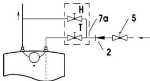
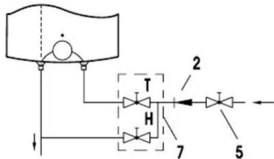
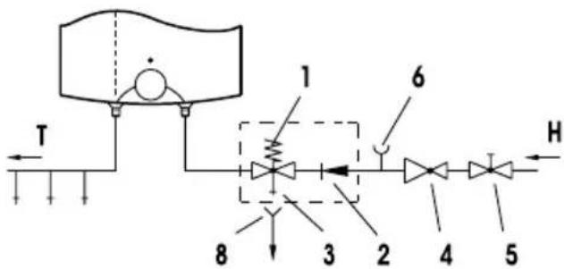
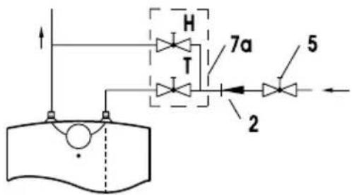
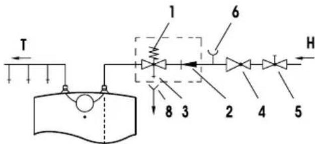
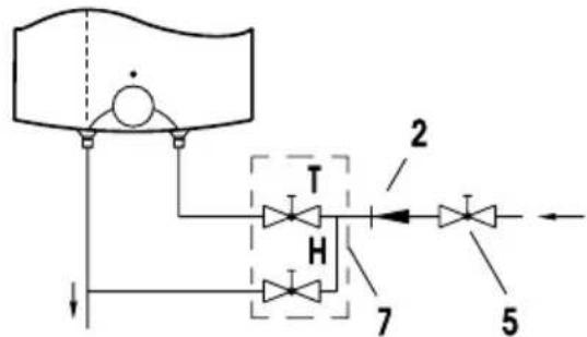
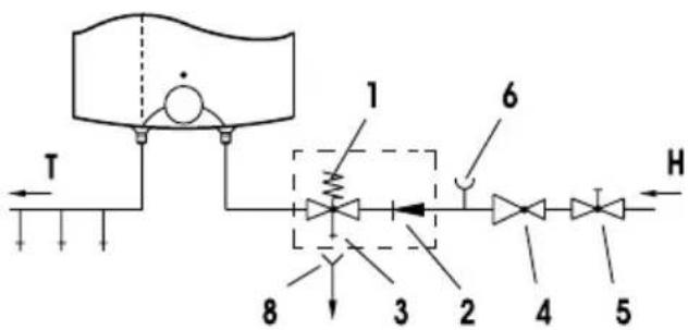
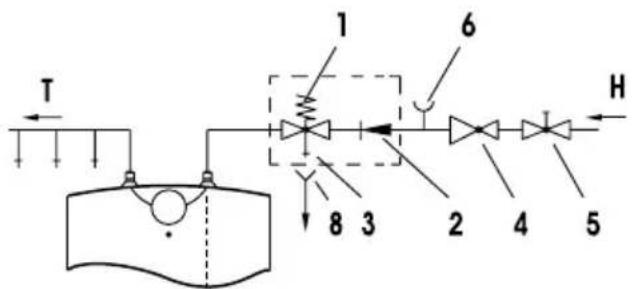
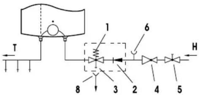
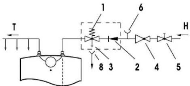
By open non-pressure system it must before the water heater a non-return valve be built-in preventing the running of water of the tank if in the network the water runs short. By this system of connection, the cross-flow mixing tap must be used. In the water heater, due to the heating the volume of water is increasing, which causes the dropping of water of the mixing tap pipe. By strong squeezing of knob of the mixing tap the dropping of water can not be prevented, but the mixing tap can only be damaged. By closed pressure system of connection on the outlet spots the pressure mixing tap must be used. For safety reasons the supply pipe must be fitted with a return safety valve or alternatively, a valve of the safety class that prevents the pressure in the tank from exceeding the nominal pressure by more than 0.1MPa .
By heating of water in the water heater the pressure of water in the tank is increasing to the limit which is adjusted in the safety valve. Because the return of water back to the water supply is prevented, dropping of water from outlet opening of the safety valve can occur. The dropping water may be let to the outlet over an intercepting accessory which is placed under the safety valve. In order to do this you should first unscrew the protective cover off the water heater.
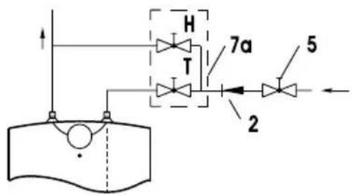
Open-circuit (gravity) system Closed-circuit (pressure) system
Installation above the basin/sink
Installation above the basin/sink
Installation below the basin/sink Installation below the basin/sink
Legend:
1 - Safety valve 7 - Mixer tap - installation above the basin/sink
2 - Non-return valve 7a - Mixer tap - installation below the basin/sink
3 - Test valve 8 - Funnel outlet to the drain
4 - Pressure-reducing valve
5 - Stop valve H - Cold water
6 - Testing piece T - Hot water
The stop valve must not be installed between the water heater and safety valve, as this would disable the safety valve.
The water heater may be connected to the water supply system without the pressure-reducing valve, provided the supply mains pressure is less than 0.5MPa . The water heater must be filled with water prior to being connected to the power supply. The hot water tap must be open during the initial filling of the tank. The tank is full when the water starts flowing through the tap and into the sink.
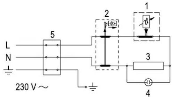
POWER CONNECTION
The water heater shall be connected to the power supply by an electrical cable fitted with a plug. Should the existing cable replaced by a new, longer cable, the new cable should be connected to the lead and the wires screwed to the connectors. In this case the water heater should first be disconnected from the power supply. For safety reasons a switch should be installed on the lead connecting the heater to the power grid, i.e. a switch disconnecting both power supply poles with the minimum of 3mm distance between the open contacts.
The water heater must be connected to the power supply in accordance with the requirements set out in the relevant standards applying to the electrical installations.
WARNING: The appliance must be disconnected from the power supply prior to doing anything that requires you to open the body of the water heater!
Legend:
1 - Thermostat
2 - Thermal fuse
3 - Heating element
4 - Light indicator
5 - Connector
L - Phase lead
N - Neutral lead
-Earthlead
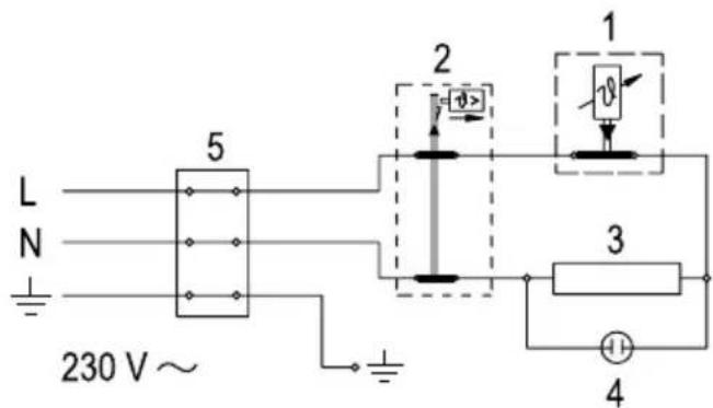
Electrical installation drawing
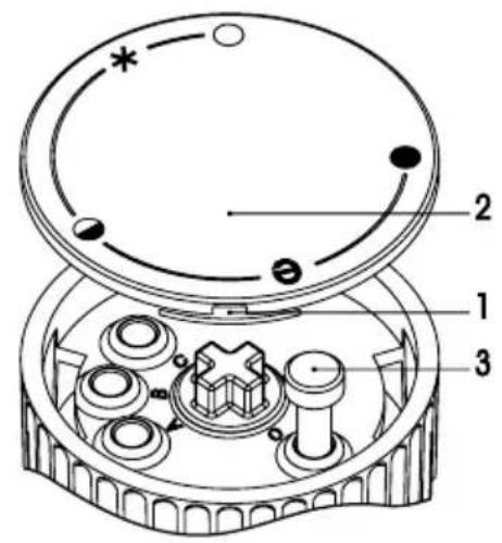
The water heater is ready for use once it has been connected to water and power. By turning the thermostat knob on the front side of the protective cover, water temperature can be set between 25^ , position "0" and 75^ , position "●". We recommend that the knob be set to position "e" as this ensures the most economic operation of the water heater. This way the water temperature is maintained at 55^ . The operation of the heater at this temperature level also results in reduced build-up of calcium and lime, as well as reduced heat loss than is the case at higher temperatures. Due to safety reasons you can optional-
ly set the highest temperature value of water in the heater. Proceed as follows:
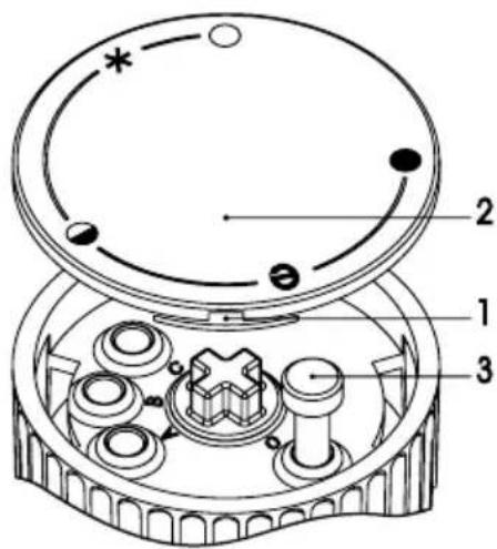
a) Insert screwdriver in slot 1 and remove button cover 2,
b) Set knob limiter 3 to any desired temperature value,
C-35°C
B-45°C
A-55°C
O-75°C
c) Replace knob cover 2 to the knob.
The operation of the heating element is indicated by the light indicator that stays on until the temperature in the tank has reached the set level or until the heater has been deliberately switched off. When the water heater is not in
use for longer periods of time, it should be protected from freezing by setting the temperature to " ※ ". Do not disconnect the power. Thus the temperature of the water in the tank is maintained at about 9^ . Should you choose to disconnect the power, the water heater should be thoroughly drained before the onset of freezing conditions. The exterior of the water heater may be cleaned with a mild detergent solution. Do not use solvents and abrasive cleaners.
Regular preventive maintenance inspections ensure faultless performance and long life of your heater. The first of these inspections should be carried out by the authorised maintenance service provider about two years from the date of installation in order to check the wear of the protective anticorrosion anode and remove any build-up of calcium and lime as required. The build-up of calcium and lime in the water heater depends on the quality, quantity and temperature of water flowing through the heater. The maintenance service provider shall also issue a condition report and recommend the approximate date of the next inspection.
In the event of the heater breaking down, you are kindly requested to contact the authorised maintenance service provider located closest to you. Please do not attempt to carry out any repairs yourself.
Poštovani kupće, zahvaljujemo Vam se za kupovinu našeg artickla.
MOLIMO DA PRIJE UGRADNJE I PRVE UPOTREBE GRIJAÇA POZORNO PROČITATE NAPUTKE
UREDAJ NIJE NAMIJENJEN NA KORISTENJE ZA OSOBE (UKLJUCUJUCI DJECU), SA SMANJENIM FIZICKIM, PSIHICKIM ILI SENZORNIM SPOSOBNOSTIMA ILI NEDOSTATAK ISKUŠENJA OZ. SAZNANJA, OSIM AKOSE NADZIRE ILI SU OBRAZOVANI U POGLEDU KORISTENJA, OD OSOBE KOJA JE ODGOVORNA ZA NJIHOVU SIGURNOST.
DJECA TREBAJU BITI POD NADZOROM, KAKO BI SE OSIGURALO, DA SE ONI NE IGRAJU S UREDAJEM.
3aTbOpeHa CnCTeMa (noHaHaHaHe)
MOHTaK HaMnBka
MoHTaK IOI MNBKa MoHTaK IOI MNBKa
JIereHda:
1-3auntha knana 7-CmeCNTeJeH kpaH - npn MOHTaK HAD MNBka
2-HeBb3BapTeHBeHTn7a-CmecnteJeH KpaH -npMOHTaX NOd MNBKa
3-Knana 3a TeC8-ФyHnA
4-Kna3aHaMaJIraBaHe HaHaJIraHaTeO
5-CTonnpawa KnaHa H-CTydeHa Boda
6 - Tectoba уacT T - Tonla Boda
Стонираца Тклana He може дбъдe моHTираha Мжду boйлepа И пpeДпa3нЯ BeHTи, Тьн KaTO TOВa пpeч Ha pa6OTaTMy.
BoiJIepbT MoKe Da 6bJe CBbp3aH 6e3 Da e Heo6xOdM MOHTaK Ha HamaJIaBaIaHaIraHeTo KIana, aKO HAIraHe To B Tp6bTe e Do 0,5 MPa. IpeDn Da CbPKeTeB eEeKtpueckata MpeKa HAnbJIHete BoJnepa C Boda. Ppr IIpbBOHaUHIO IIJIHeHeKpaHa Ha TOIIaT BODa Tp6Ba Da 6bJe OTBOpEH. BoiJIepbTe IIbIeN KOrato BODaTaCBO6OJHO N3TuHa OT KpaHa B MNBkata.
CbbP3BAHE KbM ENEKTPNueCKATA MPEKA
Бойерът се CBьрЗВа в МржКаТпocрEDCTBOM Ka6e 3aBbPbBaUc C ueNceI. Ka6eЛь може Да Бдe 3aMeHЯн C NO Dblr, OT CbSry BIVd. 3a Да NOdmEHTe Ka6e NaBpBO N3KlOuYeTe OT eJeKtpnueckaTа МржA. Heo6xOДmO e Дa 6bDe cna3eHo pa3CTOraHNeTO OT 3 MM npri KJIeMITE Ha TepMOДBoiKaTа, BoiIepьт Trp6Ba Дa ce BkLIOUH KATO 6bDaT cna3eHn N3NCKBaHnRA Tprn MoNTaJx Ha eJeKtpnueeCKn UpeDiN.
BHIMAHNE:Пре徳 КаКьВTO Ида e peMOHT Или пофнlaHTиka Ha ypeDA ИЗКЛючete OT eLEKТрчecKaTa Мржа!
JIereHda:
1 - Tepmoctat
2 - TepmoDBoNka
3 - HarpeBaten
4-CBeTJIINHeH INDInKaTOp
5-Bpb3ka
L-Φa3a
N-Hyna
-3a3eMaBaHe
Cxema Ha eJekTpueckKaTa Bpb3ka
H3PbKKA
Cnei Cbbp3BaHe KbM eIeKtpnueckata N BODHATA Bpb3Ka i Cnei PpBOHaayaleh Tect,ypeT e roTOB 3a paOta. Kato Bbpntte konyeto Ha TePMoCTata, KoETo ce HAMnpa OTnped, BHe onpeDJIeTe JEnaHata Temnepatypa B dnaHana3OH ot 25^ ,No3nun " O"do 75^ , No3nun "●". IpenOpbUbame Bn TePMocTaTbT da e B noJooKeHne " e", KbDeTo peKIMbT ha paOta e Han-ikHOHomuH n Temnepatypata e OKOLO 55^ . Ipn Ta3n Temnepatypa ce ry6n Han-MaIKo ToPJIInHa n Ce OTlara No-MaIKo BapOBnK Ha Kopnyca Ha BoJnEpa, OTKOJIKOTo pN NO-BvNCOKITE Temnepatypn. 3apaN 6e30nacHocT ce npdeBnKda peryJauaun
Ha BODaTa:
a) OTBepka ce BkapBa B npolyka 1 n otctpaHra KaapanyKa Ha konyeTo 2,
b) C konyeTo 3 ce noDbnpa Jekana TaemepaTpa,
C-35°C
B-45°C
A-55°C
O-75°C
c) Kanayka Ha konyeTo 2 ce Bpbua Ha MeCTOTO u.
Pa6otata Ha ypeDa MoKe Da ce KOHTpOInpa ot cnHaalHata NaMnUka. Ta CBetn DOkato 6bde DOCTnHata n36paHata TemnepaTypa nnN ypeBt
6bde n3KIOUeH OT eIeKTPnueckaT MpeXa. BoIIepbT HMa BrpaDeH TepMOMeTbp, KOITO NOKa3Ba DOCTnIHata TEmnepatypa. Ako ypeDbT HMa da ce n3NON3Ba 3a Dblr TepNOd OT BpMe, He ro n3KIOUcBAIte OT eIeKTPnueckaT MpeXa, Ho 6bJeTe CnryphNy che ppe3 TO3N TepNOd HMA da 6bde OOnyCHato 3Ampb3BaHe KATO NOCTaBITE TepMOCTaTa B NOLOKeHne *". BODATA B BOINepa ige Ce IODlbPjka Ha TeMnpaTypa OKoNo 9^ . Ako BCE naK NCKaTe Da n3KIOUHTe OT eIeKTPnueckaT MpeXa, n3TOUeTe PpeDvapntelHO BODATA OT BOINepa, 3a Da He 3AMpb3He. IOnuCTBaIte BbHShocTTa Ha BOINepa c npenapat. He n3NON3BaIte npenapatn, KONTO MORAT da ro nobpeJr!
PepOBHnTe cepBn3Hn npereNn ue yIbIhKat XHBota Ha 6oJIepa. IpenOpbYBaMe Bn IIpBOTO NOceSeHne Ha cepBn3EH TexHk Da 6bJe HApPaBeHO 2 rOHNn CJEd BKIOUcBaHe Ha ypeHa. Ppr TOBa NOceSeHne TPr6Ba Da ce NocHTn HacNoJIInrT Ce BapOBHK, YNeTO KOJIueCTBO 3aBnCn OT KaueCTBaTa Ha BOdaTaN3noJ3BaHaTAtemNepaTypa. Ppr IIpBOTO NOceSeHne cepBn3HnT pa6OTnK ige ONpeDEn n DaTa 3a CNEDaUTo.
Hnkora He ce ONHTBaIte Da OTCpaHbATE Bb3HNKHaII NOBpeDN Camn, a HHΦOpMnpaIte Hau-6JIH3KNr cepBN3eH ueHTbp.
Stimate cumpárator, vã multumim pentru ca ati cumpârat articolul nostru!
VÀ RUGÁM CA INAINTEA MONTÄRII SI A PRIMEI INTREBUINTARI A
(ÍNCÁLZITORULUI DE APÀ) BOILERULUI Să CITITI CU ATENTIE
INDRUMÁRILE ŞI MODUL DE FOLOSIRE
PREZENTUL APARATUL NU ESTE DESTINAT UTILIZÁRII DE CATRE PERSOANE (INCLUSIV COPIII) CU REDUCEREA FIZICE, SENZORIALE SAU MENTALE APTITUDINILOR, SAU A LIPSEI DE EXPERIENCE Şİ CUNOSTINTE, CU EXCEPTIA CAZULUI IN CARE LI S-AU OFERIT SUPRAVEGHERII SAU REFERITOARE LA UTILIZAREA DE PREGÂTIRE A APARATULUI CU PERSOANA RÁSPUNZÂTOARE DE SIGURANTA ACESTORA.
COPIII TREBUIE SÄ FIE SUPRAVEGHEAT PENTRU A SE ASIGURA CA ACESTEA SÄ NU SE JOACE CU APARATUL.
TEXHnUKNOCOSEHOCTNHAANAPATOT
| Тип | GT5O | GT5U |
| Зафатниа [I] 5 | ||
| Номинален п ratник [MPa] 0,6 | ||
| Текина / наразлесу сб вора [kg] 7/12 | ||
| Протныкорозноа за!Тида на КOTеЛOT emajширан / Мг пода | ||
| Ja"ина на[elektри"нnot гpeja" [W] 2000 | ||
| Прinksу"ен наюн [V~] 230 | ||
| Вре'mе на загвашило 75ст¹) [min] 1 | ||
| Коли"сан'tо на мe!ана бODE при 40ст [I] 9 | ||
| Уnotpeба на[eнергija²) [kWh/24h] | 0,25 |
1) Bpeme Ha 3aqrEbaHe Ha ueKynHata BHaTpe!HocT Ha rpea"OT co eJektpn"Hoto rpeano npi BHe3HaTa TemepaTypa Ha naHata BOda oD BOdoBodot 10^
2) EHeprncka noTpolyBa"ka npn oDpKyBaIbe Ha cTalHa TeMnepaTypa Ha BODaTa BO rpea"OT 65^ n npn TemnepaTypa Ha OKoJInHaTa 20^, Mepeno cnopei DIN 44532.
93BEd6a haI naBa6o 93BEd6a noI naBa6o
ПРИКЛУЧУBAнБЕ HA BOДОВODHATA!PEЖА
IeBknte 3a IOBOH n ODBoH Ha BOa ce oOeHN. IOBODT Ha CTydeHa B0a e oOeH co MoDpa a ODBODT Ha TOnla B0a naK co CpBeHa 6oja.
Ipealkata MokeTe Da ja npnkny"nte Ha BOIOBOHa Mpeka Ha Dba Ha"nHa. 3aTbopeHnot, npntcesen cnCTem Ha npnkny"yBaHe OBO3MOKyBa yNtpe6a Ha BODa od NOBeKe N3JIbHN MeCTa, OTBOPEHNOt CNCTem 6e3 npNTcOK NaK Do3BOJyBa cMo EOHO N3JIbHO MecTo. 3aBnCHO OD n36paHnot CNCTem Ha npnkny"yBaHe Mopate Da oBe36eDITE N COOdBETH Me!aHn bATEpHn. Kaj OTBOPEHNOt CNCTem 6e3 npNTcOK, pnd rpealkata Mopate Da BRpaINTe npOTNBNOBpAteH BeHTnKoj ro CnpE"yBa HCTe"yBaHeTO Ha BODaTa OD KOteIOT aKO BO BOIOBOHDATA MPeka Hema BODa. Kaj Toj CNCTem Ha npnkny"yBaHe Mopate Da yNtpe6bnte npoto"Ha MelaHn bATEpHja. Bo rpealkata 3apadN 3arpeBaHe ce 3rOleMyBa BOLyMeHOT Ha BODaTa a Toa npedn3BnkyBa Kaenebe OD ueBkata Ha Me!aHnata bATEpHa. KanEheto He MoXete Da ro CnpE"nte HHTy co 3ateraHe Ha pa"Kata Ha Me!aHnata bATEpHa. 80 Toa moXete bATEpJaTaca mo Da ja o!TeTne.
Kaj 3aTBopeHnOt npHTncEH CnCTeM Ha npNKJy"YBaHBe Mopate Ha n3JIbHNte MeCTa da yNtpe6nte npHTncHm Me!aIHH bATEpnn. Ha DOBOHaT a ceBkA nopadn 6e36eHocT ha pa6OTeHBeTo 3aDoJIKNHeTNO Tpe6a Da Ce BrgaDN CNrpyHOCEN BeHTIN NII CNrpyHOcHa rpyna, Koja cnpe"YBa NOBn!YBaHBe Ha npHTncOKOT BO KOTeNt 3a NoBeKe od 0,1 MPa n3HaD HopMaIhHor.
Kaj 3arpeBaHbeto Ha BODATA BO rpeaIkata, npHTncOKOT Ha BODATA BO KOTeJOT Ce 3rolemyBa Do rpaHnucata Koja e peRyInpaHa BO CNrpyHOCHNOT BEHTn. PndejKn BpKaHbeto Ha BODATA Ha3aD Bo BODBOHDaT MaPexa e CnPpe"ENO, MoKe Da ce noJaBN KaeneHe Ha BODA OD n3INBHNOT OTBOP Ha CNrpyHOCHNOT BEHTn. BODATA Koja KanemOjTe Da ja Haco"ITE BO ODBODT ppeky IOBeUOT, KOJ Mopate Da ro HameCTnte Nod CNrpyHOCHNOT BeHTn. ODbODHata ueBka HameCTeHa NOD NCnyCTOT Ha CNrpyHOCHNOT BeHTn Mopa Da 6nde HameCTeHa BO HAcoka IpaBO HAnony N BO MecTo KaDe !TO He 3amp3yBa.
OTbOpEN (npTooueH) cnCTem 3aTbOpEHnO T cnCTem Ha npHTncOK
I3BeI6aHaIJaBa6o
H3BéI6a HauIaBa6o
H3BeI6a noJ naBa6o H3BeI6a noJ naBa6o
Legenda:
1-Cnryphocen BENTIN7- Ppotoounha 6aTepejna 3a MeuHaHe - n3BeJaHa nAd JaBa6o
2 - Henobpateh BeHTn7a - Ptoouha 6aTepeJa 3a MeuHaE - H3BeD6a noJlaBa6o
3-Po6eH BeHTn8-OdINBnK CO npNKnyOK Ha OJBO
4-PeDyUHOHeNBeHTn3aPnTnCOK
5-3aTbOpEN BENTIN H-JaHa BOa
6 - Побна наста К - Тona Вда
Mery rpeaot n 6e36eHOCeH BeHTn He cMee Na ce BrpaN BeHTn 3a 3aTbapaHe, 6nJeKn Co Toa paOteHeTo Ha 6e36eHOCeH BeHTn 6n 6nlo OHeBO3MOKeHo.
IpeaOT MoKe Da ce npKnyuHa KaKaBa BOOBOHa MpeHa 6e3 peDyKcNCKNt BENTIN DOKOJIky npTnCOKOT Bo MpeKaTa e noH3OK oD 0,5 MPa.
IpeE eKtpnHTo npKnyBaHe, rpeaOT 3aOJKeTEnHO npBO Tpe6a Da ce HanoHn Co Boda. IprnpBOTO nonHeBe OTbOpTe ja paKaTa 3a Tonna Boda Ha 6atepnjata 3a MeShaHe.
Ipeaot e HanoHET Kora BODaTeue npeky N3JIeBHata ZEBKa Ha 6atepnjata 3a MeShaHe.
BapnjaHTa n3HaJ yMnBaOHnKa
3aTbOpEN (cHCTeM nOД npHTnCKOM)
BapnjaHa n3Ha yMnBaOHnKa
BapnjaHaTnCNoD yMnBaOHnKa BapnJaHTa nCNoD yMnBaOHnKa
JIereHda:
1-CnryphocnBentn7-IpotoTuHa6aTepuJa3aMeuHaBe-HaYMNBaOHKOM
2 - HenobpaTHn BeHTn 7a - IpoToUHa 6aTePnja 3a MeuHaBe - yMnBaOHnKOM
3 -Прбн В entn8 -Лeвak ca npNKbUyKOM 3a OJBOd
4-PeDyKUHOHBEHTNIpNTnCKa
5-BloKpHn BeHTn H-XnaHa Boda
6 - Побни HabТаВak T - Тona ВОДа
H3meby 6oJIepa n cHrypHOCHor BeHTnla He cMeTe da yrpaInte 6JOKnprHn BeHTnI, jep 6N TIme OHemoryhnn paad cHrypHOCHor BeHTnla.
Bojlep Moxete da npKbuyte Ha KyhHy BOIOBOHy MpeKy 6e3 peDyKcHOr BeHTnla. Ako je npTncak y MpeKn HxN oD 0,5 MPa.
Ipe npKbyeHa ha eEeKtpnHy MpeKy, 6oJlep Mopate Hajnpe oBaBe3HO da HanyHnte BODom. PpNIkOM npBor nyHeHa, OTBOPte pyuCy 3a TOnNy BOy Ha 6aTepnj 3a MeShaBe. BoJlep je nyn KaDa BOda Noteue KpO3 N3NHBny ueB Ha 6aTepnj 3a MeShaBe.

- JereHda:
- CHILDREN SHOULD BE SUPERVISED TO ENSURE THAT THEY DO NOT PLAY WITH THE APPLIANCE.
- INSTALLATION
- CONNECTION TO THE WATER SUPPLY
- Legend:
- The stop valve must not be installed between the water heater and safety valve, as this would disable the safety valve.
- POWER CONNECTION
- WARNING: The appliance must be disconnected from the power supply prior to doing anything that requires you to open the body of the water heater!
- MOLIMO DA PRIJE UGRADNJE I PRVE UPOTREBE GRIJAÇA POZORNO PROČITATE NAPUTKE
- JIereHda:
- Стонираца Тклana He може дбъдe моHTираha Мжду boйлepа И пpeДпa3нЯ BeHTи, Тьн KaTO TOВa пpeч Ha pa6OTaTMy.
- CbbP3BAHE KbM ENEKTPNueCKATA MPEKA
- BHIMAHNE:Пре徳 КаКьВTO Ида e peMOHT Или пофнlaHTиka Ha ypeDA ИЗКЛючete OT eLEKТрчecKaTa Мржа!
- H3PbKKA
- ПРИКЛУЧУBAнБЕ HA BOДОВODHATA!PEЖА
- H3meby 6oJIepa n cHrypHOCHor BeHTnla He cMeTe da yrpaInte 6JOKnprHn BeHTnI, jep 6N TIme OHemoryhnn paad cHrypHOCHor BeHTnla.
Brand : GORENJE
Model : GT5UC6
Category : Boiler