Purity 450 Steam - Water filter BRITA - Free user manual and instructions
Find the device manual for free Purity 450 Steam BRITA in PDF.
| Product Type | Water filter for steam ovens and traditional ovens |
| Brand | BRITA |
| Model | Purity 450 Steam |
| Dimensions (L x D x H) | 249 mm x 222 mm x 408 mm |
| Weight (dry/wet) | 10 kg / 12 kg |
| Power supply | Mechanical (option: electronic display with 10-year battery) |
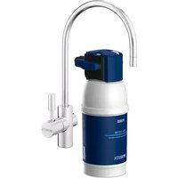
| Main functions | Decarbonation, scale reduction, selective elimination of calcium, magnesium, heavy metals (lead, copper), reduction of turbidity, organic impurities and chlorine residues. Adjustable bypass setting (positions 0-3). Comparative capacity: 2754 liters. Nominal flow rate: 60 l/h. Option: ACS electronic display indicating remaining capacity, bypass, replacement date. |
| Maintenance | Clean the exterior with a damp cloth. Replace the filter cartridge every 6 to 12 months (max 12 months). Replace the hoses every 5 years. Replace the complete system every 10 years. Regularly check for leaks. |
| Safety | Use only with drinking water. Water temperature: 4°C to 30°C. Pressure: 2 to 6.9 bars. Install a shut-off valve and a non-return valve. Protect from frost and aggressive detergents. Do not open under pressure. Maximum lifespan of pressure chamber: 10 years. |
| Spare parts | Filter cartridge (ref. 1000653), hoses, gaskets, electronic display, reducer 1"/3/4". |
| Repairability | Replacement of cartridge, hoses and display possible by qualified personnel. Legal warranty of 2 years. |
| General information | Filtration system designed to optimize tap water in steam and traditional ovens. Manufactured by BRITA. Storage/transport: -20°C to 50°C. |
Frequently Asked Questions - Purity 450 Steam BRITA
User questions about Purity 450 Steam BRITA
0 question about this device. Answer the ones you know or ask your own.
Ask a new question about this device
Download the instructions for your Water filter in PDF format for free! Find your manual Purity 450 Steam - BRITA and take your electronic device back in hand. On this page are published all the documents necessary for the use of your device. Purity 450 Steam by BRITA.
USER MANUAL Purity 450 Steam BRITA
1 Definition of Terms
2 General Information
3 Operating and Safety Instructions
4 Installation
5 Commissioning a New Filter
6 Replacing the Filter Cartridge
7 Filter Capacity
8 Repair
9 Query Mode
10 Troubleshooting
11 Battery
12 Technical Data
13 Order Numbers
Français Page 37-53
STM 4 = PURITY 450 Steam
STM 6 = PURITY 600 Steam
STM 12 = PURITY 1200 Steam
FIN 6 = PURITY Finest 600
FIN 12 = PURITY Finest 1200
Filtersystem PURITY 450 Steam/PURITY 600 Steam/PURITY 1200 Steam
1 Definition of Terms
Pressure Vessel
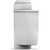
② Filter Cartridge
Pressure Vessel Lid
④ Connector Head (optionally with measuring unit)
⑤ Display Unit (optional)
6 Inlet Hose
⑦ Connection Inlet Hose
⑧ Terminal Device Connection
Flush Valve with Water Outlet
10 Connection of Outlet Hose
Filter Change Sticker
⑫ Kick Loops
13 Ejector Base
⑭ Display of the Display Unit (optional)
15 Lock
16 Mantle Handle
⑦ Reducer 1"-3/4"
18 Transport Protective Cap
19 Bypass Screw
20 Lid Handle
2 Flush Hose
2 General Information
2.1 Function and Application
The BRITA PURITY Steam water filter system optimises tap water specially for combi ovens and conventional ovens. It decarbonates drinking water, thereby reducing scale deposits in and on the terminal equipment. Depending on the bypass setting, calcium and magnesium ions as well as heavy metal ions such as lead and copper are selectively removed from the drinking water. In addition, the filter material not only reduces cloudiness and organic impurities but also substances that impair smell and taste, such as chlorine residues.
The bypass setting, which is specially designed for combi ovens and conventional ovens, matches the reduction in the carbonate hardness to the local water hardness in order to achieve an optimum filtrate quality. The increased flow and the reduced pressure loss enable the smooth operation of the combi oven.
The filter systems are available in three different filter system sizes (PURITY 450 Steam, PURITY 600 Steam and PURITY 1200 Steam), each in a version without integrated measuring and display electronics or with measuring and display electronics (Advanced Control System, ACS Technology). Filter systems with ACS Technology show you the current remaining capacity and bypass setting of your filter cartridge, the set type and size of the filter system and the last replacement date of the filter cartridge. This ensures optimum filter control and water filtrate quality. Further information on the filter system with ACS Technology can be found in Chapter 5.2.
2.2 Guarantee Provisions
The PURITY Steam filter systems are subject to the statutory warranty of two years. A guarantee claim may be asserted only if all instructions in this manual are followed and observed.
2.3 Storage/Transport
Adhere to the ambient conditions in the Technical Data (Chapter 12) for storage and transport.
The manual should be seen as part of the product and kept for the whole service life of the filter system and passed on to subsequent owners.
2.4 Recycling/Disposal
Disposing of this product and its packaging in the correct manner protects people and the environment.
The battery and display unit must not be burnt and must not be disposed of in domestic waste. Please ensure that these are disposed of correctly, in accordance with local regulations. See also Chapter 11.
Used filter cartridges can be returned to the BRITA addresses listed (see back of the cover).
3 Operating and Safety Instructions
3.1 Qualified Personnel
Installation and maintenance of the filter system may be carried out only by trained and authorised personnel.
3.2 Correct Use
The product can only operate perfectly and safely if it is installed, used and serviced in the manner described in this manual.
Note: the filter system and system-specific PURITY Steam filter cartridges may only be used upstream from end devices such as hot air steamers, combi ovens and conventional ovens.
3.3 Liability Exclusion
Installation must be performed precisely in accordance with the instructions in this manual. BRITA shall not be held liable for any damage, including subsequent damage, arising from the incorrect installation or use of the product.
3.4 Specific Safety Information
- Only water of drinking water quality may be used as intake water for the BRITA water filter system. The BRITA water filter system is only suitable for cold water use within the water intake temperature stated in Chapter 12. No microbiologically impaired water or water of unknown quality may be used without prior appropriate disinfection.
- If there are official instructions to boil tap water, the filter system must be decommissioned. When the requirement to boil water comes to an end, the filter cartridge must be replaced and the connections cleaned.
- For hygiene reasons, the filter material of the cartridge is subjected to a special treatment with silver. A small quantity of silver, which is harmless to health, may be released into the water. This is in compliance with the World Health Organisation (WHO) recommendations for drinking water.
Note for people with kidney disease or dialysis patients: During the filter process the potassium content may be increased slightly. If you suffer from kidney disease and/or have to stick to a special potassium diet, we recommend prior agreement with your doctor. - The water filtrate is classified in Category 2 according to DIN EN 1717.
- BRITA recommends that the filter system not be decommissioned for a long period. If the BRITA PURITY Steam filter system is not used for several days (two to three days), we recommend that the filter system be flushed with at least X litres according to the table below. After stagnation periods of over four weeks, the filter should be flushed with at least Y litres or else replaced. Please also note that the maximum usage period of the filter cartridge is twelve months (Chapter 6).
| Filter system Flush quantity X | after 2-3 days stagnation | Flush quantity Y after 4 weeks stagnation |
| PURITY 450 Steam 6 litres 30 litres | ||
| PURITY 600 Steam 12 litres 60 litres | ||
| PURITY 1200 Steam 24 litres 120 litres |
The filter system is not resistant to heavily concentrated cleaning agents (e.g. bleach, chlorinated solvents, heavy oxidants) and must not come into contact with them.
- The filter system must not be opened or dismantled during operation. The filter cartridge must not be opened.
- The pressure vessel and the pressure vessel lid of the filter systems have a service life of up to ten years (from the date of installation), provided that they are installed and used correctly and the operating conditions outlined in the Technical Data chapter are adhered to. They must always be replaced after a maximum of ten years. The hoses must be replaced in rotation after a maximum of five years.
Production date:
| Production code sticker filter cartridge and box, example: B612002010 | |
| 6 Production year, here: 2016 | |
| 12 Production week, here: calendar week 12 | |
| 002 Batch | No. of filter medium, here the second batch filled in terms of quantity |
| 010 Serial | number of the filter cartridge, here the tenth cartridge from the second batch |
| Production code sticker connector head - Example: 1001801 E 619316008764 | |
| 1001801 | BRITA identification number |
| E Supplie | ID |
| 6 Production year, here: 2016 | |
| 19 Production week, here: calendar week 19 | |
| 3 Production day from Monday (1) to Friday (5), here: Wednesday | |
| 16 Production year, here: 2016 | |
| 008764 Serial identification number | |
| Production date of pressure vessel and pressure vessel lid, example: 0315 |
| 03 Production month, here: March |
| 15 Production year, here: 2015 |
3.5 Safety Assembly Instructions
- The terminal device operated with the filter must be free of limescale prior to installation.
- Protect the filter system from sunlight and mechanical damage. Do not assemble near sources of heat and open flames.
- A stop valve must be installed before the filter system intake hose.
If the water pressure is higher than 6.9 bar or if there are statutory requirements, a pressure reducer must be installed before the filter system. - A non-return valve tested by the DVGW has been factory-installed at the water intake of the filter head.
- No copper pipes and no galvanised or nickel-plated pipes/connectors may be installed between the water filter and the consumer. The use of BRITA hose sets is recommended here. When choosing the material for parts that come into contact with water after the BRITA filter system it must be remembered that, due to the process, decarbonised water contains free carbon dioxide.
- All parts must be installed in accordance with the country-specific guidelines on the installation of drinking water facilities.
- For erection and operation of the filter system, the BG rules "Working in Kitchens" of the Specialist Committee "Foods" of the BGZ (BGR111) must be observed.
4 Installation
Caution: Prior to installation, read the Technical Data (Chapter 12) and the Operating and Safety Information (Chapter 3). After the product has been stored and transported at temperatures below 0^ , it must be stored with the original packaging open for at least 24 hours at ambient temperature (Chapter 12) before commissioning.
4.1 Delivery Scope
Prior to installation, remove the entire delivery scope from the packaging and check that everything is present:
1 x Pressure Vessel ①
1 x Pressure Vessel Lid ③
1 x Filter Cartridge ②
1 x Manual
1 x Carbonate Hardness Test
1 x Sticker for Service Pass (orange)
1 x Adapter 1"-3/4"
If parts of the delivery scope are missing, please contact your local BRITA office (see the back of the cover).
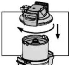
4.2 Assembling the Pressure Vessel and the Pressure Vessel Lid

- Stand with both feet on the kick loops 12.
- Lift the pressure vessel ① and turn it clockwise until the mantle handles ⑩ are over the kick loops ⑫.
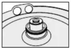
- Remove the transport protective cap 18 from the filter cartridge.
- Check that the O-ring seal of the filter cartridge ② is correctly seated in the groove and also check for dirt and damage.
Note: lubricant at the factory.
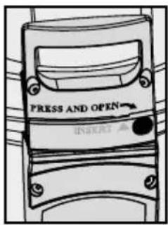
- Stand on the kick loops ⑫ with both feet and place the pressure vessel lid ③ on the pressure vessel ①. The position of the arrow marking on the lid handle ② must match the "INSERT" groove.
- Press the pressure vessel lid ③ down and turn clockwise until the lock ⑤ engages.
4.3 Assembly of Inlet and Outlet Hoses
Note: The inlet and outlet hoses are not included in the standard scope of delivery. The use of BRITA hose sets is recommended (Chapter 13).
- Fit inlet hose 6 at the inlet of the connector head 4 and outlet hose 10 at the outlet of the connector head 4.
Note: Inlet "IN" and outlet "OUT" of the connector head 4 are equipped with O-rings as seals, therefore no additional flat seals may be used here. Check that the O-rings are seated correctly.
Caution: The max. tightening torque at the 1^ and 3 / 4'' connections must not exceed 15 Nm! Only hose connections with flat seals may be used. Hoses with conical screwed connections damage the filter head connections and invalidate any guarantee claims. Only hoses that comply with DVGW-W 543 may be used to connect the device.
Before assembly, note the direction of flow on the upper side of the filter head, "IN" = water inlet, "OUT" = water outlet. Prior to installation, note installation dimensions and operating position (Chapter 12). If no original hoses are used, the 1^ - 3 / 4 adapter supplied must be used to ensure the return valve is sealed correctly (pre-fitted in the water inlet).
5 Commissioning a New Filter
5.1 Bypass Setting for Filter Systems without and with Measuring and Display Unit
- Identify the local carbonate hardness in German hardness ^ dH (BRITA nomenclature ^ KH) using the enclosed carbonate hardness test.
- Check the bypass setting on the bypass screw 19. Note: The bypass has been set to Position 1 in the factory, and must be changed to suit the local carbonate hardness and the application (Chapter 7).
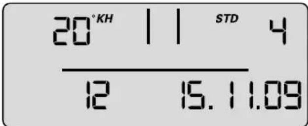
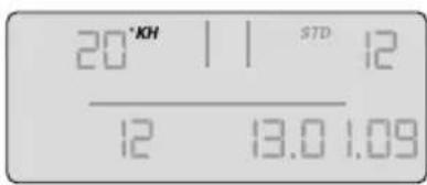
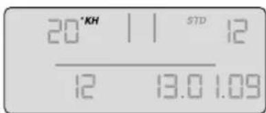
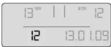
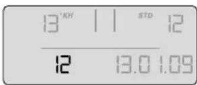
5.2 Commissioning the Filter Systems with Measuring and Display Unit
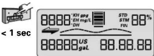
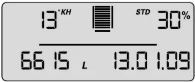
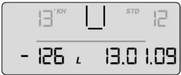
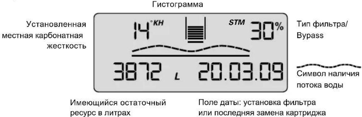
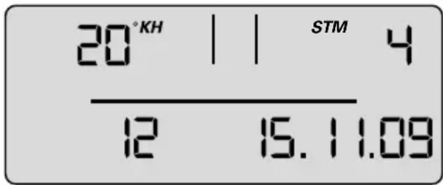
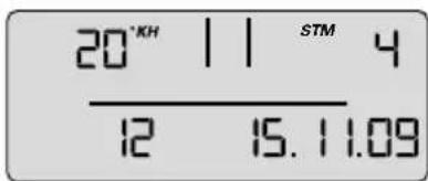
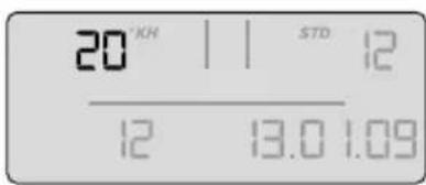
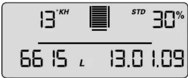
Representation in operating mode
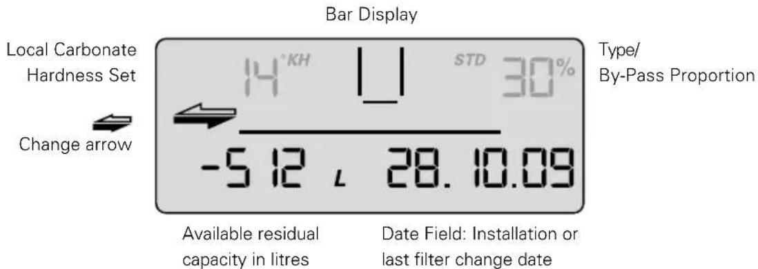
Local Carbonate Hardness Set
Bar Display
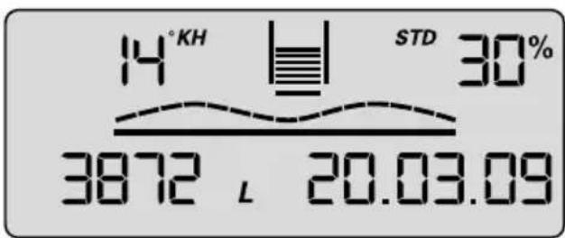
Available residual capacity in litres
Date Field: Installation or last filter change date
Type/ By-Pass Proportion
Flow Symbol
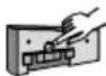
Carbonate Hardness
The units of carbonate hardness can be set as required to German ^ (= display setting ^ ), English (^ e = Clark) (= display setting ^ ), French (^ f) (= display setting ^ ), American (grains per gallon) (= display setting gpg) or international hardness values (mg/l CaCO _3 ) (= display setting mg/L).
If the setting for the type of hardness (= unit) is changed while the filter is operating, the values that were set originally are converted automatically.
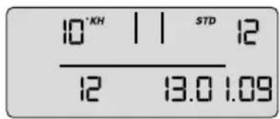
Bar chart
Representation of the remaining capacity using bar charts. After installation of a new filter system or after a filter change, the symbolised filter cartridge is completely filled with 10 bars.
Bypass proportion in percentage
The by-pass proportion is defined as the proportion of decarbonised water in the total amount of filtrate and is indicated as a percentage.
Flow symbol
When water is removed via the filter system, a graphic wave is shown on the display.
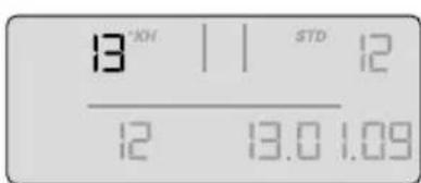
Available remaining capacity of the filter cartridge
The remaining capacity of the filter cartridge is shown in litres or in US gallons, depending on which has been selected.
When water is removed, it counts backwards in 1 litre or 1 US gallon stages. If the cartridge is already exhausted, the capacity is indicated as being negative by flashing.
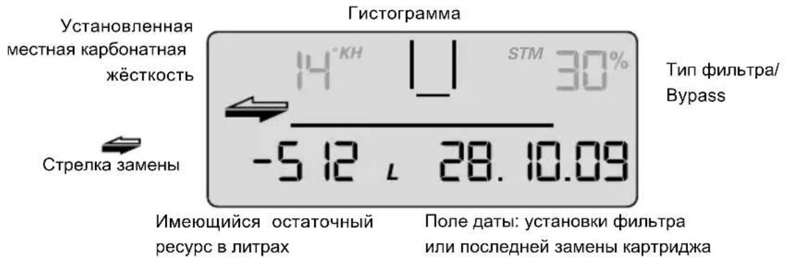
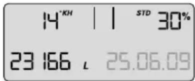
With a remaining capacity of 20% the last two bars in the bar chart start to flash.
With a remaining capacity of 10% the last bar in the bar chart flashes with the two change arrows.
From a remaining capacity of 0% the negative bars and the change arrows flash alternately with the remaining capacity shown in negative.
If the monthly limit has been reached up to a month before expiry of the set time limit, it is signalled by the date field flashing.
If the monthly limit is 100% reached, it is signalled by alternate flashing of the date field and the change arrows.
If the remaining capacity and the monthly limit are exceeded, the negative remaining capacity and the date field flash alternately with the change arrows.
Date of the filter commissioning or last filter cartridge change
The date of filter commissioning or last filter cartridge change is indicated as follows:
| Example: 28/10/09 | |
| 28 Day, here the 28th day | |
| 10 Month, here October | |
| 09 Year, here 2009 | |
Selecting the units of measurement
You can choose between European, American and international units of measurement on the display.
For European units of measurement: depending on the type of filter system (STD, STM or FIN), select the specified unit of measurement for water hardness ^ , ^ , ^ or ^ . The unit of volume and date format are then automatically displayed in litres and DD/MM/YY respectively. For American units of measurement, select gpg (unit of measurement for water hardness); the unit of volume and the date format are then automatically displayed in US gallons and MM/DD/YY respectively.
For international units of measurement, select mg/L (unit of measurement for water hardness); the unit of volume and the date format are then automatically displayed in litres and DD/MM/YY respectively.
Parameterisation
The following parameters have to be entered:
- Filter system type and size
STD 4 = PURITY 450 Quell ST
STD 6 = PURITY 600 Quell ST
STD 12 = PURITY 1200 QueLL ST
STM 4 = PURITY 450 Steam
STM 6 = PURITY 600 Steam
STM 12 = PURITY 1200 Steam
FIN 6 = PURITY Finest 600
FIN 12 = PURITY Finest 1200
Water hardness unit and water hardness value
The following units of hardness may be selected for the various types of filter system:
Unit of carbonate hardness for filter system types STD and STM:
^a KH (German unit of hardness)
^ EH (English unit of hardness)
^ FH (French unit of hardness)
gpg (American unit of hardness)
mg/L (international unit of hardness)
Unit of total hardness for filter system type GYP may be
^ DH (German unit of hardness)
^ EH (English unit of hardness)
^ FH (French unit of hardness)
gpg (American unit of hardness)
mg/L (international unit of hardness)
Monthly limit 2-12
Carbonate Hardness Type/Filter System Size
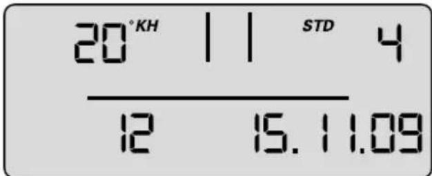
Date fieldExhaustion after months
- Reminder function filter usage period in months
Irrespective of the remaining capacity display function, you can set a monthly limit of 2-12 months to activate a reminder function for filter replacement. If the monthly limit has been reached up to a month before the export of the set time limit, it is signalled by the date field flashing. Factory set to 12 months.
Example: When set to 9 months, the date field starts to flash on the display after 8 months.
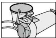
Operating the display unit
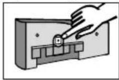
To operate the display unit, it must be removed from the connecting fittings. Slide the display housing up approx. 10mm and pull off the display unit. The display unit is operated using a button on the back of the display unit. The display unit is supplied in standby mode. To activate the display, press the button on the back once briefly and then reset after inputting the parameters.
Parameter input water hardness and filter system size
At this level, parameters needed for operation are set manually.
The type and size of filter system is selected, the unit of hardness is set, the local carbonate hardness or total hardness of the tap water is entered, and the maximum cartridge service life (monthly limit) is activated. After this the parameters must be accepted.
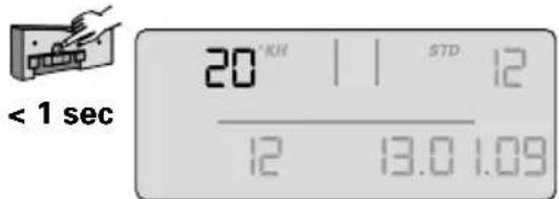
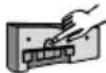
- To activate the display, press the back button once (< 1 second) until the data field appears.
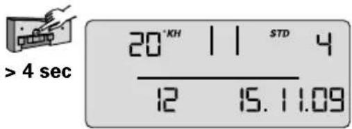
- Press and hold the button (> 4 seconds and < 10 seconds) until the parameter input for the filter system type and size flashes.
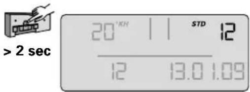
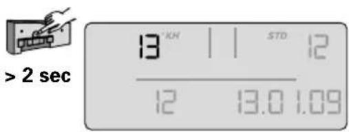
- Press and hold the button (>2 seconds) until the filter system type (STD, STM, FIN) and corresponding value for the filter system size (04, 06, 12) has been reached.
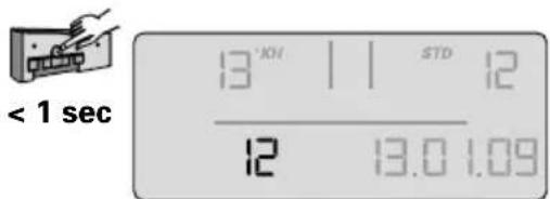
- Press the button once (< 1 second) to access the next parameter input unit of hardness. The unit of hardness flashes.
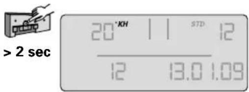
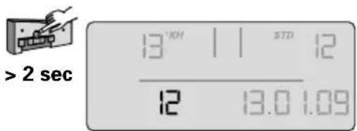
- Press and hold the button (>2 seconds) until the desired unit of hardness has been selected.
- Press the button once (< 1 second) to access the next parameter input hardness value. The hardness value input flashes.
- Press and hold the button (> 2 seconds) until the value for the water hardness rises and keep it pressed until the desired value has been reached.
- Press the button (< 1 second) to access the next parameter input monthly limit. The monthly limit input flashes.
- Press the button (> 2 seconds) and keep it pressed until the desired value has been reached.
The set parameters can now be accepted.
If you want to accept the parameters, proceed as follows:
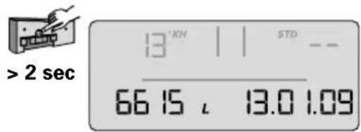
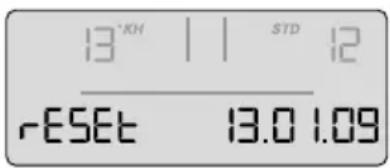
- Press the button once (< 1 second) until the message "Reset" appears and flashes.

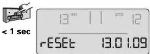
- Press the button once (> 2 seconds) until the total capacity (at 0% bypass) and the current date appear.
The set parameters have been accepted.
Note: If no input is made within 30 seconds, the display will return to standby or operating mode without accepting amended parameters.
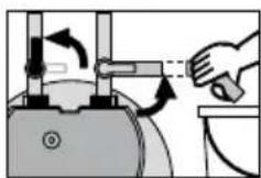
- Insert the display unit from the front at a height of approx. 10mm and slide down. The loops on the display part must be inserted in the grooves on the measuring head. Continue with Chapter 5.4 Flushing/Draining for Filter Systems with and without Measuring and Display Unit.
5.3 Bypass Setting
Determining the bypass setting
The bypass setting is identified according to the application and the carbonate hardness identified on the basis of the bypass and capacity table (Chapter 7). The bypass is then set on the bypass screw 19 as follows:
Turn the bypass screw 19 until the desired bypass (0-3) agrees with the marking.
Caution: Use 6 mm or 7/32" Allen key.
Note: Never overwind the by-pass screw to avoid any damage.
5.4 Flushing/Bleeding Filter Systems with and without Measuring and Display Unit
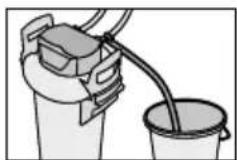
Note: A 10 litre bucket is required for flushing/draining.
- Position filter system horizontally.
-
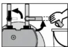
Completely open flush valve ⑨.
-
Fully open the inlet valve ⑦ at inlet hose ⑥ while holding the flush hose in the bucket. Flush with at least 10 litres of water with a minimum volumetric flow of 3 l/min (180 l/h).
-
Close flush valve ⑨, put down filter and empty bucket.
- Carefully open flush valve ⑨ while holding the flush hose in the bucket. Flush quantity once again with at least 10 litres.
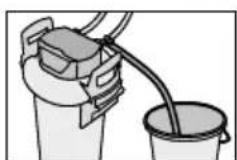
- Close flush valve 9.
- Check system for any leaks.
Note installation date of the filter system and the next exchange date on the enclosed sticker and attach it to the pressure vessel.
Note: There is space for several stickers on the pressure vessel. Apply the new sticker with the installation date at the top position.
Note: Filter systems without measuring and display units are now ready for operation.
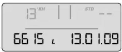
5.5 Checking initialisation of filter systems with a measuring and display unit
- Bypass setting as a percentage, remaining capacity in litres, capacity bars and the current date must be shown on the display.
Note: If these values are not shown in the display, the filter system must be flushed again (Chapter 5.4) until the values are shown in the display. Filter systems with a measuring and display unit are now ready for operation. Cf. Chapters 10.6 to 10.8.
6 Replacing the Filter Cartridge
Caution: During replacement, carefully examine all dismantled parts! Faulty parts must be exchanged and dirty parts should be cleaned. Read the operating and safety information (Chapter 3) prior to replacement. After the product has been stored and transported at temperatures below 0^ , it must be stored with the original packaging open for at least 24 hours before commissioning at the ambient temperatures for operation stated in Chapter 12.
Filter systems without a measuring and display unit
The filter cartridge must be replaced after 6-12 months and no later than 12 months after commissioning regardless of the level of exhaustion of the filter system. If the capacity of the filter cartridge has already been exhausted (Chapter 7), it must be replaced earlier.
Filter systems with a measuring and display unit
The filter cartridge must be replaced no later than 12 months after commissioning, irrespective of the level of exhaustion of the filter system. If the capacity of the filter cartridge has already been exhausted (Chapter 7), it must be replaced earlier.
If the cartridge is already exhausted, the capacity is indicated as being negative by flashing. No bars are shown in the display.
If the monthly limit for the cartridge has been exceeded, this is indicated by the date flashing.
Resetting the display unit
To operate the display unit, it must be removed from the connecting fittings.
Slide the display housing up approx. 10mm and pull off the display unit. The display unit is operated using a button on the back of the display unit.
- If this button is pressed (> 10 seconds), the data set on initial installation will be accepted again, and the capacity, bypass setting and input date are all updated.
Note: This automatically sets the monthly limit to 12 months.
Note: If no input is made within 30 seconds, the display will return to standby or operating mode without accepting amended parameters.
Insert the display unit from the front at a height of approx. 10mm and slide down. The loops on the display part must be inserted in the grooves on the measuring head.
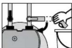
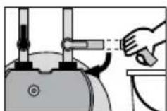
6.1 Removing the Filter Cartridge
- Switch off power supply to the terminal device (remove plug).
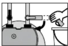
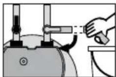
- Close inlet valve ⑦ at inlet hose ⑥.
- Place the flushing hose in a bucket and remove pressure from the filter system by opening the flush valve. Catch the escaping water in a bucket.
Note: If the escaping water is more than 1 litre, the inlet valve ⑦ is not completely closed or is blocked with scale.
-
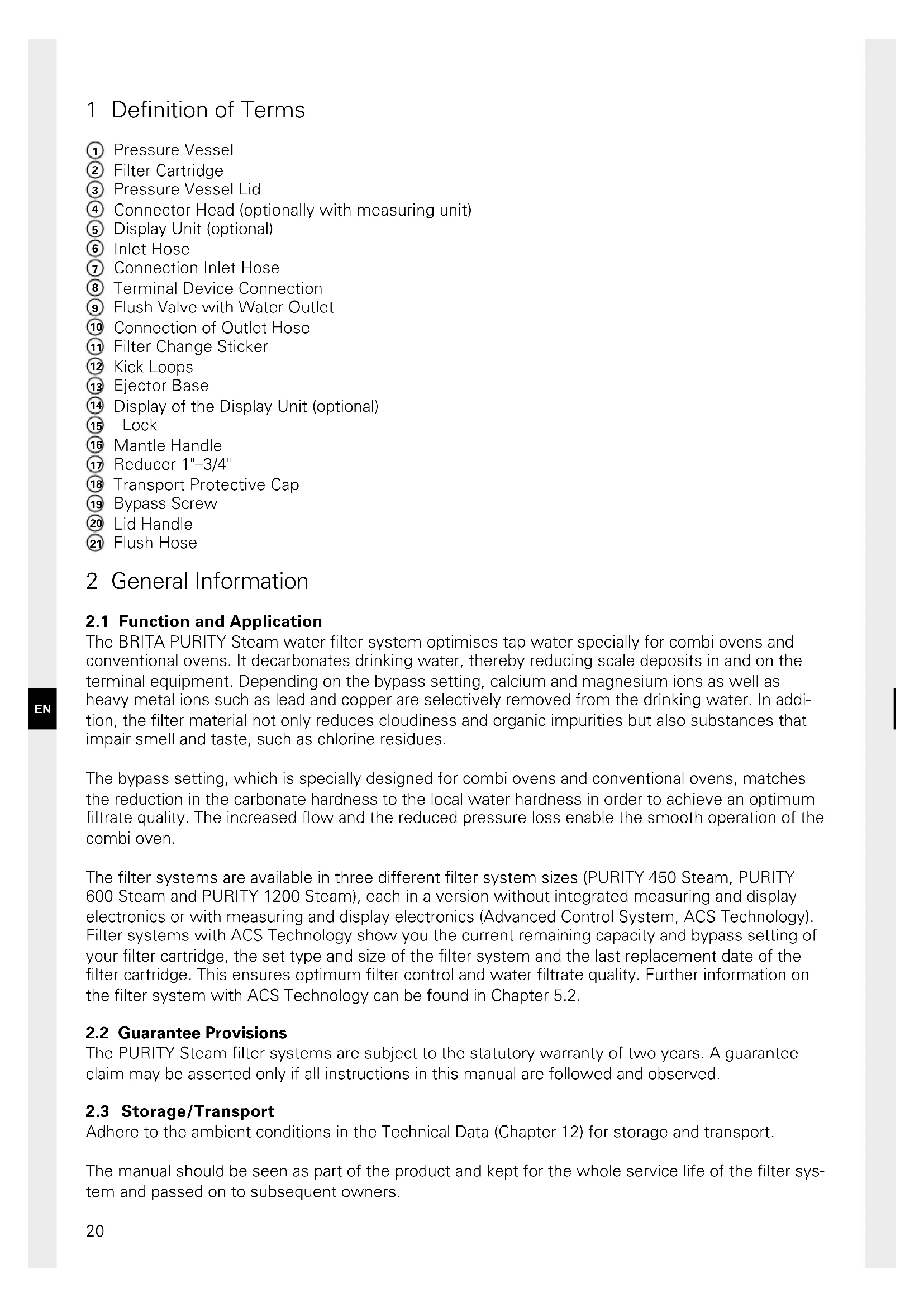
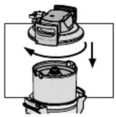
Stand on the kick loops 12 with both feet while opening the pressure vessel lid 3 by pressing the lock 15 and turning it anticlockwise as far as it will go.
-
Place the pressure vessel lid ③ vertically on both lid handles 20.
Note: Do not turn the lid horizontally on its head. - Stand on the kick loops 12 with both feet while turning the pressure vessel ① anticlockwise by the mantle handles 16 as far as it will go.
Take your feet off the kick loops 12 and press the pressure vessel 1 down with both hands on the mantle handles 16. - Remove exhausted filter cartridge ② from the pressure vessel ①.
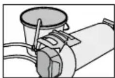
- Place the exhausted filter cartridge ② in the sink with the connection facing down to drain the remaining water (>5 min.).
- Lock the exhausted filter cartridge ② with the transport protective cap 18 of the new filter cartridge and return in the original packaging to the appropriate BRITA address listed on the back of the cover.
6.2 Inserting the Filter Cartridge

- Check the connector seat of the filter cartridge O-ring ② in the pressure vessel lid ① for dirt and damage.
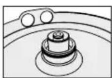
- Check that the O-ring seal of the filter cartridge ② is correctly seated in the groove and also check for dirt and damage.
Note: The cartridge seat has been lubricated with food-safe lubricant at the factory.
- Place the new filter cartridge ② in the pressure vessel ①.
- Stand on the kick loops 12 with both feet, lift the pressure vessel 1 turning it clockwise until the mantle handle 16 is over the kick loops 12.
-
Stand on the kick loops 12 with both feet and place the pressure vessel lid 3 on the pressure vessel 1. The positioning of the arrow marking on the lidhandle 20 must line up with the "INSERT" groove.
-
Press the pressure vessel lid ③ down and turn clockwise until the lock ⑤ engages.
-
Switch on power supply to the terminal device (plug).
To flush and bleed the new filter cartridge 2 carry out the steps described under 5.3.
7 Filter Capacity
Use of the PURITY Steam water filter system with integrated measuring and display unit or installation of the BRITA FlowMeter 100-700A is recommended for the precise, continuous control of the degree of filter cartridge exhaustion.
Capacity Table (in litres)
| Carbonate hardness in °KH | PURITY 450 Steam PURITY 600 Steam PURITY 1200 Steam | ||||||||
| Bypass position Bypass position | |||||||||
| 0 1 and 2 3 0 1 and 2 3 0 1 and 2 3 | |||||||||
| 4 | 5.633 | 6.134 | 6.760 | 8.833 | 9.619 | 10.600 | 16.530 | 17.999 | 19.836 |
| 5 | 5.633 | 6.134 | 6.760 | 8.833 | 9.619 | 10.600 | 16.530 | 17.999 | 19.836 |
| 6 | 5.633 | 6.134 | 6.760 | 8.833 | 9.619 | 10.600 | 16.530 | 17.999 | 19.836 |
| 7 | 4.829 | 5.258 | 5.794 | 7.571 | 8.244 | 9.086 | 14.169 | 15.428 | 17.002 |
| 8 | 4.225 | 4.601 | 5.070 | 6.625 | 7.214 | 7.950 | 12.398 | 13.500 | 14.877 |
| 9 | 3.756 | 4.089 | 4.507 | 5.889 | 6.412 | 7.067 | 11.020 | 12.000 | 13.224 |
| 10 | 3.380 | 3.680 | 4.056 | 5.300 | 5.771 | 6.360 | 9.918 | 10.800 | 11.902 |
| 11 | 3.073 | 3.346 | 3.687 | 4.818 | 5.246 | 5.782 | 9.016 | 9.818 | 10.820 |
| 12 | 2.817 | 3.067 | 3.380 | 4.417 | 4.809 | 5.300 | 8.265 | 9.000 | 9.918 |
| 13 | 2.600 | 2.831 | 3.120 | 4.077 | 4.439 | 4.892 | 7.629 | 8.307 | 9.155 |
| 14 | 2.414 | 2.629 | 2.897 | 3.786 | 4.122 | 4.543 | 7.084 | 7.714 | 8.501 |
| 15 | 2.253 | 2.454 | 2.704 | 3.533 | 3.847 | 4.240 | 6.612 | 7.200 | 7.934 |
| 16 | 2.113 | 2.300 | 2.535 | 3.313 | 3.607 | 3.975 | 6.199 | 6.750 | 7.439 |
| 17 | 1.988 | 2.165 | 2.386 | 3.118 | 3.395 | 3.741 | 5.834 | 6.353 | 7.001 |
| 18 | 1.878 | 2.045 | 2.253 | 2.944 | 3.206 | 3.533 | 5.510 | 6.000 | 6.612 |
| 19 | 1.779 | 1.937 | 2.135 | 2.789 | 3.037 | 3.347 | 5.220 | 5.684 | 6.264 |
| 20 | 1.690 | 1.840 | 2.028 | 2.650 | 2.886 | 3.180 | 4.959 | 5.400 | 5.951 |
| 21 | 1.610 | 1.753 | 1.931 | 2.524 | 2.748 | 3.029 | 4.723 | 5.143 | 5.667 |
| 23 | 1.470 | 1.600 | 1.763 | 2.304 | 2.509 | 2.765 | 4.312 | 4.695 | 5.175 |
| 25 | 1.352 | 1.472 | 1.622 | 2.120 | 2.308 | 2.544 | 3.967 | 4.320 | 4.761 |
| 28 | 1.207 | 1.314 | 1.449 | 1.893 | 2.061 | 2.271 | 3.542 | 3.857 | 4.251 |
| 31 | 1.090 | 1.187 | 1.308 | 1.710 | 1.862 | 2.052 | 3.199 | 3.484 | 3.839 |
| 35 | 966 | 1.052 | 1.159 | 1.514 | 1.649 | 1.817 | 2.834 | 3.086 | 3.400 |
The bypass position can be adjusted to the local water quality or the machine type.
The following recommendations for bypass settings apply by default:
Position 0: All devices in areas with an extremely high water hardness level ( >KH = 22^ ).
Position 1: Combi ovens and conventional ovens with direct injection system
Position 2: Combi ovens and conventional ovens with boiler system
Position 3: All devices in soft water areas (<KH=7^)
You can obtain individual recommendations from your BRITA contact.
Note: The stated capacities have been tested and calculated on the basis of common application and machine conditions. External factors (such as fluctuating crude water quality and/or machine type) can cause deviations from this information.
8 Repair
Regularly check the filter system for leaks. Regularly check the hoses for kinks. Bent hoses must be replaced.
The complete filter system must be replaced in rotation after a maximum of ten years. The hoses must be replaced in rotation after a maximum of five years.
Caution: Prior to changing, read the Technical Data (Chapter 12) and the Operating and Safety Information (Chapter 3).
Regularly clean the outside of the filter system with a soft, damp cloth.
Caution: Do not use any substances incompatible with the material (Chapter 3.4) or astringent, abrasive cleaning agents.
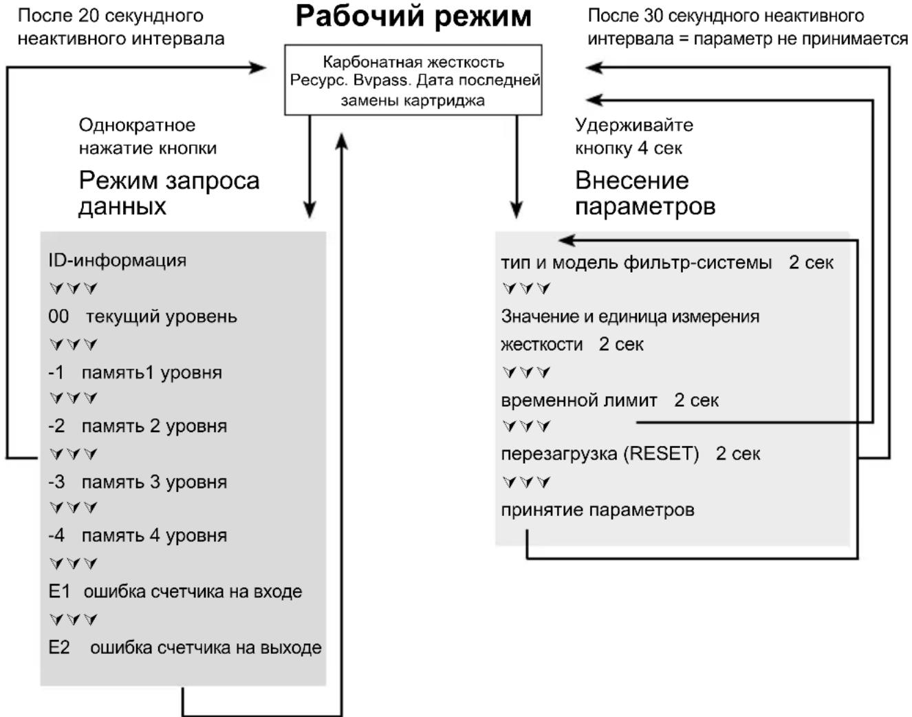
9 Query Mode
The following data can be queried in the query mode:
Production data
- Briefly press button once (< 1 second); the following message appears.
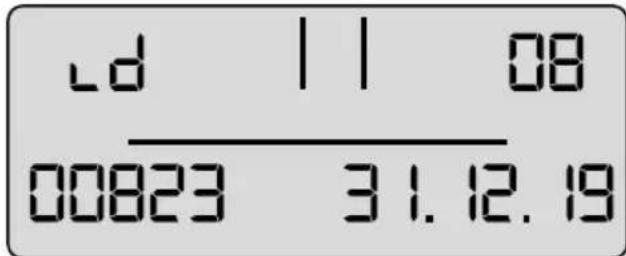
ID Level Production Year
Serial Appliance Number Battery Service Life
Production year: Example 08 = 2008
Device number: consecutive
Useful battery life: Example 31/12/19 = The battery in the display unit will be exhausted on 31/12/19 and the complete filter system has reached its max. usage period.
Total volume meter
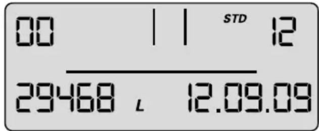
- Briefly press button twice (< 1 second); the following message appears.
00 level current data (today)
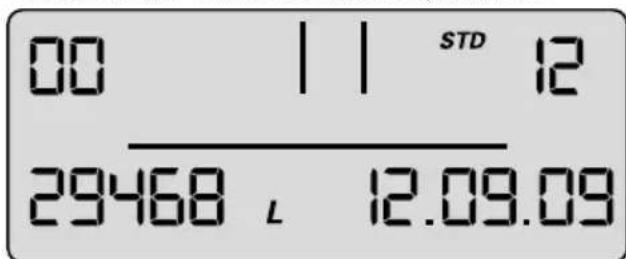
00 Indicator for current level Filter system size
Current dateTotal volume meter
The total volume meter is managed at this level; it counts up from 0 irrespective of the cartridge change.
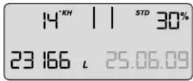
Memory Call-Up
In the Memory Call-Up mode, the data of the last 4 filter cartridges used can be called up. Briefly press button once (< 1 second) until the following message appears:
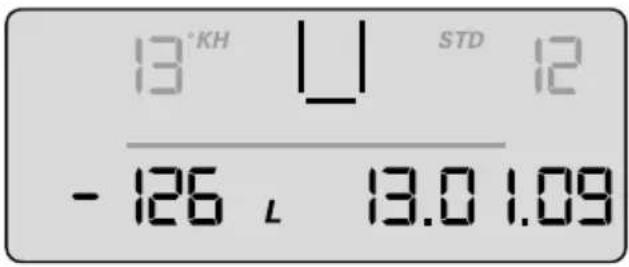
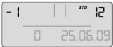
-1, -2, -3, -4 level – data of the cartridges used before the current one.
Carbonate hardness By-pass
alternating
Cartridge indicator Type
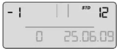
Date of inserting the cartridge
Total meter reading when changing the filter cartridge
At the top left, the indicator for the filter cartridge (-1 for previous filter cartridge) is displayed alternately with the water hardness set and the hardness unit. At the top right, the filter system size is displayed alternately with the bypass setting (display 1 s indicator, 1 s water hardness), at the bottom left, the meter reading when changing the cartridge (-1) and at the bottom right, the installation date of the cartridge.
Meaning: the filter cartridge most recently used was a PURITY 1200 cartridge, the filter cartridge was inserted on 25/06/09 and operated up to a meter reading of 23166 litres.
The water hardness set was 14^ and the bypass measured was 30% .
The same applies to the cartridge (-2), preceding filter cartridge and the other preceding filter cartridges-3,-4.
Error Messages
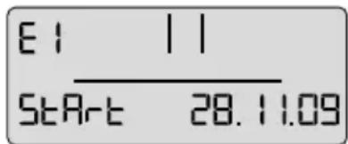
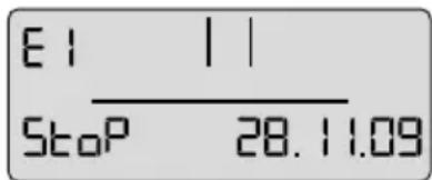
Error level E1 indicates whether an error has occurred in blend detection.
E1 is activated as soon as the current bypass is not correctly identified.
The word Start is then displayed together with the date of occurrence.
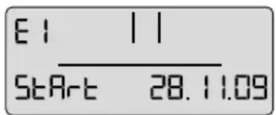
alternating

As soon as the current bypass setting is identified correctly again, the error has ended and the Stop date is added. At error level 01 the Stop and Start display alternates every second.
Error level E2 indicates whether and from when until when an error has occurred at the outlet water meter. Display is similar to level E1.
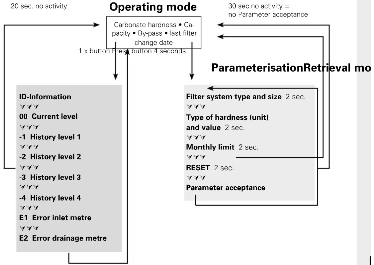
Program Overview
10 Troubleshooting
10.1 No water flow
Cause: Water intake closed.
Troubleshooting: Open water intake on the upstream stop valve or inlet valve 7 on inlet hose 6.

Caution: The following faults may be remedied only by trained and authorised personnel.
10.2 No or low water flow in spite of open water intake
Cause: Mains pressure too low.
Troubleshooting: Check mains pressure.
If the fault continues in spite of adequate mains pressure, check the filter system and filter cartridge and change if necessary.
Caution: Prior to changing, read the Technical Data (Chapter 12) and the Operating and Safety Information (Chapter 3).
10.3 Leak at Screwed Connections
Cause: Screwed connections not fitted correctly.
Troubleshooting: Check mains pressure. Check all screwed connections and mount according to Chapter 4.
If the fault continues, exchange filter system.
Caution: Prior to changing, read the Technical Data (Chapter 12) and the Operating and Safety Information (Chapter 3).
10.4 Leak after Filter Replacement
Cause: O-ring at the filter cartridge is not seated correctly.
Troubleshooting: Check correct seat of the O-ring (Chapter 6.2).
Caution: Prior to dismantling read the data (Chapter 12) and the Operating and Safety Information (Chapter 3).
10.5 No Display Function
Cause: Battery drained.
Troubleshooting: Replace display unit (Order number see Chapter 13).
Note: When replacing the display unit, follow the enclosed manual.
10.6 Data on Display Flashing
Cause: Monthly limit expired or the remaining capacity of the filter cartridge is exhausted (Chapter 5.2).
Troubleshooting: Replace filter cartridge (Chapter 6).
10.7 Bypass setting in the display does not agree with the setting of the bypass screw (cf. 10.8/10.9)
Cause: Filter was not commissioned correctly.
Troubleshooting: Flush filter again (Chapter 5.4). Check data in the display after flushing (Chapter 5.5).
10.8 Bypass setting in the display does not agree with the setting of the bypass screw (cf. 10.7/10.8)
Cause: Valve strip of the by-pass setting not set correctly.
Troubleshooting: Flush filter system again and readjust bypass screw (Chapter 5.3)
11 Battery
The installed battery is designed for a service life of approx. 10 years. The battery and display unit must not be burnt and must not be disposed of in domestic waste.
To remove the battery, please proceed as follows:
- Remove the screw on the back of the display unit and open and remove the back of the housing.
- Disconnect the soldered contacts on the battery with side cutters and remove the battery from the bracket.
- Replace the back of the housing on the display unit and tighten the screw.
Dispose of the battery and display unit following the local environmental guidelines for battery disposal.

12 Technical Data
| Filter system PURITY Steamwith filter cartridge | |||||||
| PURITY 450 Steam PU | RITY 600 Steam PURITY 1200 Steam | ||||||
| MDU* | distributor head | MDU* | distributor head | MDU* | distributor head | ||
| Operating pressure 2 bar to max. 6,9 bar | |||||||
| Operating/water temperature 4°C to 30°C | |||||||
| Ambient temperature during | operation 10°C to 40°C storage/transport -20°C C to 50°C | ||||||
| Flow rate with 1 bar pressure loss 400 l/h 500 l/h | 400 l/h 500 l/h | 400 l/h 500 l/h | |||||
| Nominal flow according to Norm | 60 l/h | 60 l/h | 120 l/h | 120 l/h | 120 l/h | 120 l/h | |
| Pressure loss at nominal flow | 0,12 bar | 0,08 bar | 0,36 bar | 0,27 bar | 0,32 bar | 0,24 bar | |
| Empty filter cartridge volume | 3,9 I | 5,8 I | 9,9 I | ||||
| Weight (dry/wet) | 10 kg/12 kg | 12 kg/15 kg | 18 kg/24 kg | ||||
| Comparable capacity according to DIN 18879-1:2007 The comparable capacity is a standardised indicator to facilitate comparison of different fi iters. The comparable capacity is determined under extreme conditions. The usable capacity in practical operation is higher than the comparable capacity and may vary greatly depending on the usage conditions. | |||||||
| Comparable capacity | 2754 I | 4734 I | 9521 I | ||||
| Dimensions complete system (Width/Depth/Height) | 249 mm/222 mm/408 mm | 249 mm/222 mm/520 mm | 288 mm/255 mm/550 mm | ||||
| The bending radii of the inlet and outlet hose 2 m, DN13, 3/4"–3/4" are approx. 130 mm and, depending on the installation orientation and operating space, must be considered in addition to the dimensions of the complete system. | |||||||
| Operating position | The filter system can be operated either vertically or horizontally. | ||||||
| Inlet connection | G 1" | ||||||
| Outlet connection | G 3/4" | ||||||
- with ACS Technology
Comparable capacity according to DIN 18879-1:2007
The comparable capacity is a standardised indicator to facilitate comparison of different filters. The comparable capacity is determined under extreme conditions. The usable capacity in practical operation is higher than the comparable capacity and may vary greatly depending on the usage conditions.
| Comparable capacity according to DIN 18879-1:2007 | |
| PURITY 450 Steam | 2754 litres |
| PURITY 600 Steam | 4734 litres |
| PURITY 1200 Steam | 9521 litres |
13 Order Numbers
Filter system PURITY 450 Steam/PURITY 600 Steam/PURITY 1200 Steam
| Article | Article number |
| PURITY 450 Steam (Complete System with Filter Cartridge) | 1000654 |
| PURITY 600 Steam (Complete System with Filter Cartridge) | 1000245 |
| PURITY 1200 Steam (Complete System with Filter Cartridge) | 1000226 |
| PURITY 450 Steam (Complete System with Filter Cartridge) with Measuring and Display Unit | 1002912 |
| PURITY 600 Steam (Complete System with Filter Cartridge) with Measuring and Display Unit | 1002918 |
| PURITY 1200 Steam (Complete System with Filter Cartridge) with Measuring and Display Unit | 1002923 |
| PURITY 450 Steam Filter Cartridge | 1000653 |
| PURITY 600 Steam Filter Cartridge | 1000252 |
| PURITY 1200 Steam Filter Cartridge | 1000231 |
1 Éléments
STD 4 = PURITY 450 QueII ST
STD 6 = PURITY 600 QueII ST
STD 12 = PURITY 1200 Quell ST
STM 4 = PURITY 450 Steam
STM 6 = PURITY 600 Steam
STM 12 = PURITY 1200 Steam
FIN 6 = PURITY Finest 600
FIN 12 = PURITY Finest 1200
Cause: montage incorrect des raccords.
STD 12 = PURITY 1200 QueLL ST
STM 4 = PURITY 450 Steam
STM 6 = PURITY 600 Steam
STM 12 = PURITY 1200 Steam
FIN 6 = PURITY Finest 600
FIN 12 = PURITY Finest 1200
Filtersystem PURITY 450 Steam/PURITY 600 Steam/PURITY 1200 Steam
By-pass in percentuale
STM 4 = PURITY 450 Steam
STM 6 = PURITY 600 Steam
STM 12 = PURITY 1200 Steam
FIN 6 = PURITY Finest 600
FIN 12 = PURITY Finest 1200
STM 4 = PURITY 450 Steam
STM 6 = PURITY 600 Steam
STM 12 = PURITY 1200 Steam
FIN 6 = PURITY Finest 600
FIN 12 = PURITY Finest 1200
STD 12 = PURITY 1200 QueLL ST
STM 4 = PURITY 450 Steam
STM 6 = PURITY 600 Steam
STM 12 = PURITY 1200 Steam
FIN 6 = PURITY Finest 600
FIN 12 = PURITY Finest 1200
STM 4 = PURITY 450 Steam
STM 6 = PURITY 600 Steam
STM 12 = PURITY 1200 Steam
FIN 6 = PURITY Finest 600
FIN 12 = PURITY Finest 1200
mg/l (international hardsened)
Enheden for totalhardseden for filtersystemtypen GYP kan vare
mg/l (international hardsened)
Mänedsbegraensning 2-12
Carbonathardhed Type/Filtersystemstorrelse
DatofeltOpbrugt after maneder
Filtersystem PURITY 450 Steam/PURITY 600 Steam/PURITY 1200 Steam
| Articlel | Articlel-number |
| PURITY 450 Steam (komplet system med filterpatron) | 1000654 |
| PURITY 600 Steam (komplet system med filterpatron) | 1000245 |
| PURITY 1200 Steam (komplet system med filterpatron) | 1000226 |
| PURITY 450 Steam (komplet system med filterpatron) med MAE | 1002912 |
| PURITY 600 Steam (komplet system med filterpatron) med MAE | 1002918 |
| PURITY 1200 Steam (komplet system med filterpatron) med MAE | 1002923 |
| PURITY 450 Steam filterpatron | 1000653 |
| PURITY 600 Steam filterpatron | 1000252 |
| PURITY 1200 Steam filterpatron | 1000231 |
1 TepMNHbI
① Kon6a BbICOKOr DaBnEHH
② CmehHbIK KapTpndK
③ TOnOBHaaTbΦnNbTp
④ BLOK NOIDKJIIOUeHn(c3JIeKTPoHHbIM DINCPJIeEM B KaueCTBe OIuIN)
5 ΘneKtpoHHbI ducnnei (onua)
⑥ BxOJHOI WJNaHr
⑦ 3a npaHou n KJanaH Ha BXoHOM ShJaHre
BbIXoHNoIuHaN DnI NOkKIOUeHnK OobpyObaHnIO
9 PpombboHbI KJanaHa npombBOOHOM JhaHre
CoeINHeHn BbIXoHOro JnHaHa
CTnKepeIaHHbIXO npON3BOmMbIX 3aMeHax KapTpNdxKei
12 OnopHbIe HOxKn
13 LOKoNb
14 3kpah 3neKtpoHHoro dncnpea (onzna)
15 3amok
6 Pyka KOn6bl BbICOKO DaBHeHn
17 POnHkaUoInepeXoHNK 1"-3/4"
3aunTHbIKoJINaOJKJIA TpaHcnpTupOBKIN
19 PerynipOBouhBn BnHT bypass
20 PyuKa rOIOBHOuACTnΦNbTpTa
② PpOmbioHbI WJNaHr
2 O6uine cBeDeHnra
2.1 PpHcHn DeIcTBn n oBlaCTn npImeHeHHa
Фиьтсntema PURITY Steam kommaHn BRITA onTmuaNPyET kaecTBO BODonpoBOHOBdI CneuaJIbHOДЯ napOKOBeKToMaTOB n dpyrnx CTmepOB. OHa DekapboH3npyET NITBeByIO BDOY IN PpeD0TbpaUaET ObpazOBAHNE n3BcEeKOBOrHa HaneTa B NOkNoeHHOM o6OpydoBAHN I HA CoedINHTeNbHbIX DeTAnX. INDbNduaJIbHna HAcTPOka bypass No3BOJAre OChCTNTb NITBeByIO BDOY OT IOHOB KaIbUaIg N MaHnA, a TAKKe TJeKbIX MeTAlNOB (B T. Y. CBInca I MeDi).ФиьТуюш МATEPnAHe ToIbKO ChnJaet MyTHoCTb N COdePkaHne opraHueckx npimeceB BOIDONPOBOHOB BoDe, HO n ydaJIaER Te UeIeCTBa, yxydUaUOuNe BKyc n 3anax, B TOM YncIe Xlop.
Блардя сецальним Hab相对较у кам bypass Дя napokOBeKToMaTOB undpyruX CTHmepOB, obecneuBaetc ChxkeHne KapboHaTHO JceTkoCTN MeCTHO BODOpBOHOB OdoI DO ONtmaJIbHOrO cTaHdapTa ФпьТрOBaHHoB OdbI. YBeJIuYeHne CKOpOCTn npOTOKa n CHxKeHne paDeHna DaBLeHn oEscneuBAHT BeCpe6oHoeФyHKUOHPOBaHne napOBbx neyei.
IocTabJIIOCTcФINbTp-CnCTeMbI Tpex pa3nHbIX TInOB (PURITY 450 Steam, PURITY 600 Steam and PURITY 1200 Steam), kaxdA n3 CnCTeM MoKeT NocTabJIaTbcRA KAc B KOMnJIeKTe C 3JNeKTpoHHbIM andnCnJIeEM (Advanced Control System, texHOrnA ACS), taK n 6e3 Hero.
Фильър-cистемьс Textногген ACS npedoctabлгот akTyajbHyu Инфорmaцию ob octaToCHOM pecypce n Hactpoike bypass CMeHHoro KapTpudka, TUNe N MOdENI Φиьър-cистемьи Ддтпocл徳н Замени Картудka. 3TO rapaHTnpyet ONTImaJIbHbI KOHTpOJIb 3a pa6OTOn Φиьъри KaueCTBOM Фильърванн ВОДы. БONEe NOdpo6HyU INHΦOPMaцию O Фильър-cистemax C Text-ногген ACS Bы habdeTeВгаве 5.2.
2.2 YcnoBn npedeOCTaBJeHnrapaHTn
Для Фильстсм PURITY Steam npedoctabЯETcra npedycmOTpeHHa 3akOHm rapaHTncaPOKOM Ha OdnH roD. ГаHTnma MoKet 6bIb npedocTabHeHa TOnbKO B CJIyae co6JIIODeHnA BCEx yKa3aHn HAcTOrIe NHCtpyKcHn.
2.3 XpaHeHne/tpaHcnpTnpOBka
Heo6xOJIMo CO6JIIOaTb ycNoBnXpaHEnn I TpaHCnOpTnpOBKn, npuBeJeHHbE B rnaBe «TexHueckne napaMeTpbl» (rnaBa 12).
Hnctpykunra yBnaeTcra HeoTbeMneMo uactbIO n3deNna, ee cneJeT XpaHnTB B TeueHne BCero Cpoka 3Kcnnyatau nn PnIbTp-cnCTeMbI N nepeDaTb nocJeDyUOeMy BnaeIbu.
2.4перетабткалуtnлзацьn
I3dene n ero ynaKbky cneDyET yTnIn3npObaTb B COOTBeTCTBm C yCTaHOBJeHHbIMn HopMaMn. B cnyuae yTnIn3aunC hapuHHeM yCTaHOBJeHHbIX HOPM BO3MOXHO HaHeCEHne cepBe3HOrO yuepe6a YelOBeku NOKpykaUoien cpe.
AkkymyIop n 3JIeKtpoHHbI dncnneH He cIeDyeT CxNrTaB N Bbl6paCbIBaTb BMeCTe C 6blTOBbIMn OTXoJam. Pn yTuIN3aun HEO6xoJMo NOHOCbIO CO6JIHOaTb Tpe6OBaHn MecTHOrO 3aKOHOaTeJIbCTBa. DOnONHHTeJIbHyU NHΦOpMauHcM. B rIabe 11.
3PykoBoDCTBO NO INcnoJb3OBaHnIO n 6e3ONaCHOCTN
3.1 KbannuunpoBaHHbI nepcoHaJI
YcTaHOBKa n O6cnyKuBaHne fNtBp-CnCTeM MOryT pOn3BOiNTbCra TOnbKO KOMNeTeHTHBIM yNoJHOMOeHHbIM nepcoHaJOM.
3.2 KoppeKTHoe obpauneHne
B HacToaSeHnCTpyKcHn ONcaH NopraDOK yCTaHOBKn, 3KcPnyTaauN n O6cnyKbAHnra, rapaHTnpyUoIne HaJIeXkaUee n 6e3OnaChoe FyHKcNoHpOBaHne n3dJIINr.
TapaHTnpUoHn: pIbTp-cntEmy n CneuaJIbHbIe CMeHHbIe KapTpJxN PURITY Steam moryT 6bIt yCTaHOBHeHbToJIbKO nepeI noTppeSIAUm obopyObaHnEM, TAKIM KAK napOKOBekToMaTbI, KOM- IN KOHBekUHOHbIe Neu.
3.3 NCKJIoueHne OTBETCTBEHHOCTN
MoTax Heo6xOIMO npOn3BOaNTb B TOUHOM COOTBeTCTBUN C HAcToauei HNcTpyKuJe. KomnaHn BA BRITA He Hecet OTBeTCTBeHHocTb 3a IIObIe y6bITKn, B TOM YncIe KOCBeHHbY uep6, KOtOpBle MOrTy BO3HNKHyTb NO pInuHHe HEnpaBnBHOY cTaHOBKn NIN HeHaJNeXaUero NcNoJIb3OBaHnE ee npOdyKuHn.
3.4 CneuaIbHa IHOpMaIgno 6e3OnaNcHOctn
BФиьтсnteMBrITABMOKETnoaBaTbCToNbKO NITBeBaBBOOnpoBOHaHbAo. ΦиьтсnteMa BRITA npedha3naeHa ToNbKO dny XoIoHOB BoDbl, TeMpepaTypa KOTopo npn noaue He BbIXOHT 3a npedeIbI, yka3aHHbIe B rIabe 12. He donyckaetc foNbTpcaJn BOOnpoBOHOBBo, codepkauei BpeHbIe MmKpOboNOrnueckne npimecu, nII BObbl, KaueCTBO KOtOpOH Hen3BeCTHo, be3 eE npedBaPtehBOH coOTBeTCTByIOUeI de3INΦeKuIN.
B Cnyaee Bo3HKnHOBeHHn OfuaJIbHbIX peKOMeHdaun O Heo6xOIMOCTH KINJyehn BODonpoBOHOI BObl 3KcPnyataun FInbTp- cNCTembl DOJXHa 6bITb ppeKpaueHa. Korda daHHoe Tpe6OBaHne 6ydt OTMeHEnO, Heo6xOIMO 3aMeHHTb KapTpndx Ha HObI, a CoedHHeHn IPOde3HNΦuHPOBaTb.
B COOTBeTCTBnC CaHITapHbIMN HopMaMn FInIbTpbl NOJLexKa TcneuaJIbHOI npOeDype 06e33apaxKuBaHnA cepe6pom. HenocpeIcTBeHNO B BOy MoKeT IOnaCTb He3HaHTeJIbHOe KOINueCTBO cepe6pa, YTO abCOIoTHo 6e3OnacHO dJa 3OpOBBy. 3To COOTBeTCTByeT peKOmeHdaqm BcemnpHOr OpraHn3aun no Oxpae 3OpOBBy (BO3) dJa NITbeBO BoBl.
BHHMaHIO JIODeI C 3a6OJIeBaHHeM NOeK I NlU, KOToPbIM IPOBOIDTCr DnAJIIN3: BO BpeM aIbTpaun BoI bI cOePkaHne B Hei KaIIra MoKeT He3HaUnTeJbHO yBeJIuHTbcr. EcII Bbl CTpaJaTe 3a6OJIeBaHnM NoeK IIIN pNdePjXnBaTeCb Hn3KOKaJIueBOI dNeTbI, Mbl peKOMeHNyEo6pATNTbcra 3a KOHCyIbTaUne K BpaCy.
- Φι NBtpoBaHHa BODa OTHocTcK KaTeOpn2 cTaHapTa EN 1717.
KOMnHnB RITA He peKOMeHdyET BbIBOAnTb fInIbTp-CnCTEmy n3 3KcIIpyaTuCmHa dIITeJIbHOe BpemB Cnyae ecn fInIbTp-cnCTema BRITA PURITY Steam He nCnoNb3OBaJacb HeckoJIbKO (OT DBx Do Tpex) DHei, Mbl peKOMeHdyem npOn3BeCTn IpomlbkU yka3aHHbIM B npInlaRaEMOn HIXe Ta6nIe obbEMOM BObl X. Ppi npocToe B TeueHne 60one Yem Yetbipex HeJeB cJeDyET npOn3BeCTn IpomlbkU yka3aHHbIM B npInlaRaEMOn HIXe Ta6nIe obbEMOM BObl Y IIN6O 3AmEHnTB fInIbTp. Ppi 3tOM CneDeYET yuHTbBaTb, YTO MaKcImaJIbHbI CpOK NcNoJIb3OBaHnA CMeHHOrO KApTrnDka CoCTaBnAET 12 MecaueB (rnaBa 6).
IpeM MoNTaXOM cneDyET n3Bnueb BCE NOCTaBnEHhie DeTaH N3 yNaKOBKn I npOu3BeCTN OCMOTp Ha npEIMET NOHOTbl KOMnNeKTaUH:
1xKoI6a BbICOKO RaBHeHn ①
1xroNoBnaHaactbΦnIbTpTa ③
1xcmehhblkapTpndx ②
1xpykoBOdCTBO no 3KcnnyaTaun
1x Tect Ha Kap6oHaTHyIO JcctKocTb
1xCTnkep nacnpTa o6cnyXuBaHna (opaHkeBbI)
1xnoHnKaaOuI nepeXoDnK 1"-3/4"
PnObHApUxKeHn HeoCTaHouX KOMNoHErTOB cTaHdAPTHoN KOMJIeKtauH NHeo6xoDmO opaTntbcra npeIcTaBntbCTBO BRITA B BaWem pernohe.
4.2 C6opka K0JI6bI BbICOKO rDaBHeHnC rOIOBHOuAcTbU OHHbTpA
BctaHbTe 06eIMNHorAMNaONOpHBie HOKKN 12.
- PpHNOHMnTe KOn6y BbICOKOr DaBHeHna ①, NOBopaunBaIe ee no YacOBon cTpeNke Do Tex Nop, NOKa pyuKn KOJIbblcOKOr DaBHeHna 16 He BCTaHyT npaannelbHO ONOpHbIM HOKKam ⑫.
- CHIMTE c KaptpnJka 0nIbTa 3aunTHbIK KOJINaUOK dJa TpaHCnOpTIpOBKn 18.
CneyuET npOBepntb npaBnIbHocTb nocaKn KOJIbueO6pa3Horo yNIOHTHNTeJRA KapTpua ② BnpEyCMOTpeHHOM yrIy6NeHm n, y6eINTBcB B OTCyTCTBn rpa3n I NOBpeKdEHN.
Примочанe:Ha 3aBOde nocaoHoe rHe3do KapTpndka o6pa6oTaHO NIISeBOI cMa3KoI.
- Hactynite 06eHmH Horamn Ha onOpHbIe HOxKn 12 n pa3MeCTne rOIOBHyO qactb 3 Ha kon6e ①. MecTo pacnoJoxeHn cTpeKn Ha pyKe rOIOBHO qactn 20 DoJXHO npn 3TOM COBnaCTb C yrny6NeHem INSERT.
HaIaBHTe Ha roIOBHyIO qAcTb Ⅲ IOBepHITe ee no YacBOOCTpeJIke Do 3auePHeHnC 3aMKOM 15.
4.3 YcTaHOBka BxOJHORIO N BbIXOJHORO JHaHROB
PpimmeaHne: BXOHOH N BbIXoHOn IJNaHrN He BXOJrT B CtAHdAPTHbI KOMJIeKT NOKJIIOUeHnA cnBbTp-CnCTEmbl.
BxOJHOH JNaH 6MOHTnpyeTcHa BxOJe,a BBIXoHOH JNaHr-Ha BbIXOJe 6Joka NOKJIIOUeHn4.
PpmeaHne: BxO IN N BbIXoD OUT 6noka nOdkIoueHni 4 ChabkeHb KoIbceOp3HbIMN yNtHTeTnMn, NO3OMy He CnEpyet nCNoB3OBaTB DoONHHTeHbIe PNOCKne npOKnaDKN. Heo6xoIMO yOCTOBepntbcra B KOPpeKTHOM paCnoJIOXeHN yNtOTHTeJIeN.
BHMaHne: MaKcMaJIbHbI BpaUaIOuM MoMeHT dJa CoeINHeH N 1"- n 3/4" He doJxHnpeBbIaTb 15 Hm! IcnoJIb3yIte TOnbKO coeINHeH N JNaHROB C PNOCKIMN npoklaKaMn. UHaHr c KOHuecko pe360I NOBpeXdAHOt MeCTa CoeINHeH N 6JOKnOyeH N, YTO npIBoDIT K UTPaTe npaba Ha rapaHTnHoe O6CnyKBaHne! Dna NOkInOeH N K O6OpyoBaHNo MOrTy NCNoJIb3OBaTbcra UHaHr, COOTBeTCTByIOuNe cTaHdApTaM DVGW-W 543.
IpnMOHTaXeФnIbTpcaO6JIIOJaTe HAnpaBHeHne NToKa,06O3HaueHHeCtpeNockamnHa NOBepxHOCTn 6IOKa IOnKIIoUeHn:IN=BxOJBOdbl,OUT=BBIXO BODbl.Heo6xoDmO yuHTbIBaTb yCTaHOBOUHbIe pa3MepbIΦnIbTp-CNCTeMbI n ee pa6Oee NIOJOKeHne (rJaba12).EcnnncnoJIb3y- IOTcA HeOpRnHaJIbHbIe UJNaHr,BOcNOJIb3yITecb NOHXaHOUM nepExoDHNKOM
1"3/4" (npnnaeraetc) nЯ obecneueHЯ repMeTuHocTn KlaNaHa o6paTHoro TeueHn, npedBapntbHo yCTaHOBNeHHoro Ha BXOe 6Loka noKlnoueHn.
5 BbOaB 3KcIpyatauHOBOro nIbTpa
5.1 Hactpoika bypass B cnIbTp-cnCTeMax, o6OpydoBaHHbIX n He o6OpydoBaHHbIX 3JIeKTPoHHbIM dncnJeem
- OnpeJeIte Kap6oHaTHyO JkctKocTb MeCTHO BODbI B rpaDycax HeMeUcKOJ XeCTKOCtN (°dHc, cornachO TepMnHOJorIN BRITA ^) c nOMoBIO npunaraemoro Tect-KomnJIekTa.
- Дя сньсгсгш PURITY Finest: onpeeinte obu yox kctkocb MeCTHO BdI B rpaaycax HeMeucko jecTKocTn (°dH, cornacho tepmnoJorn BRITA °GH) c nomou bpo npnilaraemoro Tect-KOMnkeTa. IpoBepte noIOxehne peRynpoBOUHO BHTa oBODa 19. Ppimueahne: pa6pnHra yctahOBka oBODa - 30 %, npn Heo6xoIMOCTH ee MOxHO n3MeHHTb C yETom KapboHaTHO JecTKocTn MeCTHO BoDbI N Oco6eHHOCTe INPImHeHnA (rnaBa 7).
5.2 BbD B DeIcTBnE fNtBp-CnCTeMbI, 6OpOyIOBaHHo 3NeKToHHbIM dncnneem
Pa6oun pexm ducnpj
KapboHaTha JecTkoctb
Пижелань можно Вьбпаь HeMeцкne dH (= Hactpoika Диспля _KH), aHRnNCKne (°e = Clark) (= Hactpoika Диспля _EH), Фразузckne (°f) (= Hactpoika Диспля _FH), ceBepoa-Mepinkahckne (grains per gallon) (= Hactpoika Диспля gpg) и Мжdyapodныe (Mr/л CaCO 3) (= Hactpoika Диспля Мr/Л) edHnUbI KapboHaTHOH JxecTKOCTN.
EcnB XOe 3KcNpyataunn fNbTpa n3MeHReTc Tn ( = eDnHua) xeCTKOCTN, aBTOMaTneckn nepeCHTbIbAOTcYCTaHOBJIeHHbIe paHee NOKa3AHJ.
Tnctorpamma
I3o6paXeHne ocTaOuHOro pecypca c NOMOuTo rNCTOrpaMMbl. Iocne yCTaHOBKn HOBOI nIbTp-CnCTeMbI nn 3aMeHbI fNtbpCa CmBON CMeHHoro KaptpnJa KaMOnHCTpnpyET HanoJIHeHHocTb Ha 10 deJeHn.
Bypass
Bypass onpeenraetc kak dona He dekapboHn3npoBaHHo BODbIB ObueM KOINueCTBe. hnIbTpoBaHHo BObl N yka3bIBAeTcB INpOeHTax.
CnMBOJ HAIHINI NOtOKA BOBbl
Pn noctynneHN BObbl B nIbTp-cntemy Ha 3kpahe OTO6paxaetcBONHnCTaJIHHN.
Imeuicra octaToHbI pecypc KaptpnJa
OcTaToUHbI pEcypc KapTpua yka3bBaetcno Bbl6opy B IITpax IInbo R raIIHOx CUSA. Pn noCTynpeHn BΦnBtp BoBt HauHaetc o6paTHbI OTCuET B IITpax IIn B raIIHOx CUSA, KaJdbI shar paBeH 1 nItpy nn rAINOhy. Pn nCuePnaHn KApTpIxKem CBOero pecypca Ha 3kpaHe oTo6paXaetc MrraIOoee OTrpuTeNbHoe 3NaeHne pecypca.
Ipn DoctnHexeHnn OCTaToHbIM pecypcom Noka3aTeJn B 20% OCTaBUnecra Dba DeJeHnra TnCTOrpamMbI HauHaOT Mrratb.
Pn DoctnxkeHn OCTaToHbIM pecypcom nokaTeB 10% nocJeDHee DeJeHne TnCTOrpaMMbI HaunHaet MuraTb ODHObpemEHNO C DByMc TpeKamN «3ameHa».
Ipn DoCTnxKeHn OcTaOuHbIM pecypcom noka3aTeB B 0% Muraet DeJeHne ructorpaMMbl, yka3bBaIOUe Ha OTPuCaTeNbHbI pecypc, a TAKKHe IonepeMeHHo MraIoT cTpeIKN «3ameHa» I OTPuCaTeNbHoe YncNo OCTaTOHOro pecypca.
Korda do ncteHn BpeMeHHOro (B Mecaux) pecypca fNbTpa oCTaetc OINMecu, cnHaHIN3npyET 6tOM Mraouee none daTbi.
Korda BpemeHHo pecypc fNJIbTp-CnCTeMbI nCepnaH ha 100 %, nonepeMeHHO MIRaOT CTpeKN «3aMaHa» I noJe DaTbI.
Korda octaToHbI IN BpeMeHHoN (nocJeHm MecA) pecypcbI pInbTp-cnCTembl npeBbICrT 100%-n nopor, ob 3tOM cHraHn3npyIOT NOJ OTpuCaTeJIbHOro OCTaTOHOrO pecypca N daTbI, KOtOpble MiraIOT nonepMeHHO co CTpeKNAM «3aMeHa».
DOnKHbI 6bITb 3aHaHbI cNeNyUOuHe npaMeTpbl:
TnN MoeJIb 0nIbTp-CnCTeMbI
STM 4 = PURITY 450 Steam
STM 6 = PURITY 600 Steam
STM 12 = PURITY 1200 Steam
- EdinHua n3MepeHn I 3NaueHne JeCTKoCTN BObl
Moryt 6bItb BbIbpaHb CneDyIOUe eDHNuJxKecTKoCTN:
Eduina KapboHaTHoJ XeCTKocTn DJIa HbTp-CnCTem Tuna STM:
KH (Hemeukar eunnua jxecKoCTn)
EH (aHnnckae ennnaeKcctKoctn)
FH (papuy3ckay eHHnua kectkoctn)
gpg (eɪnHɪza kecTkocTn CllA)
Mr/JI (MeJyHapOHaHa eINHua JecTkoCTn)
BpeMeHHoI npedeJb 2-12 MecaeB
Kap6oHaTHa JecTkoCTb
TIN/MoDJIbΦNJIbTp-CNCTeMbI
(B MeCraux)
noJe DaIbBpeMeHNo pecypc
-ФункцинаноминьяобoctabшемсВрмehHom pecypce nIbtpa B Mecaax
He3aBnCIMo OT HAcTpoKn FyHKcN INHdNkaCmN OCTaToCHOr opecypca Bbl MoKeTe yCTaHOBnTB BpeMeHHoI nped2-12 MeCAeB dIra AKTbAaCn FyHKcN HAnOMHaHnO Heo6XoDnMOCTn 3aMeHbI KapTpndka. KOrda Do nCTeueHn BpeMeHHoro pecypca fNJIbTp aOCTaETcOIN MeCAu, DJIa npedynpexJdeHn HaunHaet MInrTa b NOIe daTbI. 3aBOdCKo HAcTpoKo IpEduCMOTpeH cPOK 12 MeCAeB.
PpMep: npn HacTpoKe Ha 9 MecaeB pa6oTbI NOle DaTbI Ha 3KpaHe 3NeKTPOHOrO DnCnJIe HauchET MIRaTb YpeE3 8 MecaeB.
YnpabJIeHne 3JekTpoHHbIM dncnIeem
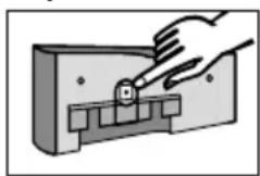
Дя уравлиеня злжкгоньIM дисплелем erO Heo6xODIMO n3Bleych n3 6LOka nodklIOUeHn. ПОднIMITE злжкгоньIM dIcspBv npIMepHO Ha 10 MM n CHIMITE erO DBIXKeHnEM BpepeI. 3JIeKgTOHHbI dIcPJIeN pporpaMMpyetcA c NOMOu bIO nepeKJIIOUaTeJIa (KHONKI)Ha erO 3aDHeI naHEnI.
3aBODsKa HAcTPOka 3neKtpoHHoro DnCnpe - pexm OxuHaHna. JIra AKTbauCuN DnCnpe KpaTKOBpeMeHHo HaxMITE paCNOJKeHHbI C 3aDHeN CTopoHbI nepeKnUoyatelb 1 pa3 N npOBeDuTe nepe3arpy3ky NyTe M BBOda HObIx napaMeTPOB.
YcTaHOBka npaMeTpOB JecTKoCTN BOdbI N MoJeJN qInbTp-CnCTeMbI
3deBpyHOMpeKIMBEBOJrTaDaHHbIe,Heo6XoDnMbIeIpaobTbIΦnIbTpA.
IponcxOJNT BbI6Op Tnna N MoJeN fHJIbTp-CNCTeMbI, eHNuCbI JcEeKTOCTN, BBOd 3HaueHnA KapboHaTHoJ JcEeTKoCTN MeCTHO BODonpoBOHOB BoDbl N aKTNaBaun MaKcMaJIbHOrO cPoka CnyXbI KapTpndJa (BpeMeHHoe OrpaHnueHne B Mecraax). IocNe 3Toro npaMeTpbl DoJxHbI 6bITb npHrTbl.
-ДяakTnBaCINДиCnIeRcIeDyETKpaTKOBpeMeHHO HaxaTb nepeKniOuAteIb (KHOnKy) 1 (< 1cekyHdbI)do NOBHeHnNoJa DaHHbIX
- YdepKINBaTnepeKnIOuATeNb CNeIyET Do Tex nop (>4 cekyni < 10 ceynd), noka He 3amiraet noJe DnRA BBOa Tnp NMOJI N MOnJIbTp-CNTEmbl.
- YdepxnBaTb nepeKnIOuATeINb DO Tex nop (> 2cekyH), noka He oTo6pa3ntc Heo6xOIMbI TnI PhInbTp-cnCTembl (STM) n ee moJeB (04, 06, 12).
Haxkab KhoNky 1x (< 1ceKyHbI) dny nepexoJa K BBOdy cneDyIOUeRo npaMeTpTa: eINHua JecTKOCTN. EINHua JecTKOCTMnraet.
- Haxkatabu ydepxnbatb nepeknquatebn (> 2 cekyH), noka He 6ydt BblpaHa Tpe6yeMa eHNuza XeCTKoCTn.
HaxaTb nepeKIOUaTeIb 1x (<1cekyHdbI)ДЯ nepexOda K BBOy3HaueHnJ XeCTKOCTN.Mraet NOKa3aTeIb XeCTKOCTN.
- YdepxnBaTb nepeKnIOuataIb (>2CEK yHd) IyBeJIueHn NOKa3aTeIg JxecTKoCTN BODbl Do Tex np, NOKa He 6yDet DOCTNRHyTa Heo6XOIMma BeINuHa.
Haxatb nepeknoyateIb 1x (<1cekyndbl) npepexoanda K BBOdy napameTpba BpeMeHHoro pecypca (Mecya). Mraet none dny BBOda.
Haxmatab ydepxnBaTb haxaTbIM nepeKIOUaTeIb (>2 cekynd) do tex nop, noka He 6ydt DOCTURHyTa HEO6xOIMma BEINuHa.
<1sec

4sec
2sec
<1sec
2sec
<1sec
2sec
<1sec
2sec
Teneb 3aadaHHbe npameTpbl Moryt 6bItb 3arpyxkeHbl (npHnraTbl).
ДяЗунnapaMeTpoB Heo6xOIMO cTeNaTb cNeDyIouee:
- HaxkaTb nepeKlIOuAteIb 1x (< 1 cekyHdbI) do nOBnEHH coo6UeHH Reset, KOtOpoe NaHcET MIRaTb.
- HaxaTb u ydepxuBaTb nepeKluoyaTeIb 1 x (>2cekyHd)do nOBLeHnCtPOKn o6uee EMKOCTN (npu bypass 0% ) n aKtyaJbHoN daTbl.
<1sec

2sec
YcTaHOBJIeHHbIe npaMeTpbl 3arpyKeHbl (npnHrTbl).
PpmeaHne:ecnB TeueHne 30 ckyHn H6oJee daHHbIe He BBOyTc,3KpaH nepeXoNTBa6Ouyn peKm,a BBedeHHbIe npaMeTpbl He 3arpykaOTc (He npHHMaOTc).
BCTaBbTe 3JektpoHHbI dncnneB n a3 6NoKa noKJIuOeHn Ha rny6Hy np6bn3ntbHO 10 MM n onyctnte ero do ynpa. BbictynbHa 3JektpoHHom dncnnee doJxHb6bItb BCTaB- IeHb I na3bl 6NoKa noKJIuOeHn. PpOdoJXeHne cM. B rnaBe 5.4 «PpOmbiBaC/cnyck BoDbl DnF pNlbTp-cnCTeM, obOpudOBaHHbx H e o6OpudOBaHHbx 3JektpoHHbIM dncnneem
5.3 Hactpoika bypass
Onpeelenenhe hactpoyn bypass
HactpoKa bypass npOn3BOJNTcHa OCHOBaHH TaBnUpeCypcoB n HactpoKn bypass (rna7) B COOTBETCTBn C 06NaCTbIO npImeHeHn yCTaHOBJIeHHbIM 3HaueHnem KapboHaTHO JecTKoCTn MEcTHoB BOOpPBOJHO BODbl. 3aTeM npOn3BOJNTcH AChtpoKa bypass c NOMOu bpopeyInpoBOuHOro BNHTa 19:
PerynpoBouhB BINT NOBOPaHbAeTcA OTHOCHTeNbHO uKaJIbI (0-3) Do COBnaJeHn yka3aTeJc Tpe6yEMbIM 3HaueHHeM.
BnMaHne: noJb3yIeTc6 bJra 3TOrO wecTnRpaHHbIM KJIIOYOM 6 MM UIN 7/32".
BnMaHne: BO n36eXaHne NOBpeXdEHN peYInpOBOuHbI BNHT HAcTpoKb bypass HeJIb3r NOBOpaUHBaTb DaIbSe, Yem Do yNopa.
5.4 PpOmbIbKa/cnyck BOdI dIy qHJIbTp-cnCTeM, o6OpyIOBaHHbIX n He o6OpyIOBaHHbIX 3JIeKTPoHHbIM DnCnIeem
PpmeHne: npoUeDpyb IpomBIBKn/Cnyska BoDbI NoHaIO6ntc 10-nITpOBoE BeDpo.
- YctaHOBtE qHJIbTp-CnCTeMy B ROpN3OHTaJIbHOe NOJIOKeHHe.
- PONHOCTbIO OTKPOIte IpOMbIOHbIKaIIaH 9.
- PONHOCTbO OTKPOIte 3aIIpaHouN KJIaHAn ⑦ paONIOJKeHHbI HA BXoDHOM WHaHRe 6, OJHOBpeMeHNO KpeNK OyepXNBa IpnMbIBOuHbI WJaHr B BeJe. IpomOIte oINbTp He MeHee Yem 10 NITpAmn BObl. MInHMaNbHa cKOpocTb NOTOKa DOJxHa CoCTaBnTb 3 J/MnH (180 J/4).
3akpoTe npombBOUHbI KnaPAn 9 nocTaBbTe pINbTp IN BblneTe Body n3 BeDpa.
OCTOPOXHO OTKPOIte npOMbIOUHb KlaHaH, pa3MeCTNB IN PPOH OydepKINBa IpOMbIOUHb UHaH B BeJe. Eue pa3 IpomOnTe FInIbTp He MeHee Yem 10 NITpAMN BObl.
3akpoTe npombBOUHbKnIaNaH 9
- Поберпсicontему на прдmet потук.
3ainnTe daty yctahOBKn fInbTp-cnCTembl n daty oupeHOn 3aMeHb KaptpnJaHa npnilaraemOM CTKepe HAKLeIe erO Ha Kopnyc KOJIbB BbICOKOr DaBHeHra.
PnmeaHne:Ha Kopnyce KoIbbl NMeetc MeCTO dJa HaKNeKN HeCKoJIbKnx CTnKePOB. HauJeBaTe CTnKepbB nopdke oupeepHOCTN CBepxu BHN3.
IpmeaHHe: Tepeb pfNbTp-cnCTema, He o6OpydoBaHHa 3NeKtpoHHbIM dncnneem, rTOBa K pa6ote.
5.5 IpoBepKa HacTpoeK fNbTp-CnCTeMbI C 3JeKToPHbIM DnCnJIeEM
- UctahOBJIeHHbIe HAcTPOJKN bypass B IpooIeHTax, OCTaToHbI peCypcB JInTpax, rictOrpamMa (JINHN) IN TeKUaJa DaTa DOJXHbI OTo6paKaTbcra Ha DnCnJIee.
IpimmeaHne: ecIn 3TN daHHbIe He OTo6paKaIOTcR, Heo6xOIMo 3aHOBO IpomblcNCTEmy (TnaBa 5.4) do Tex nop, noka daHHbIe He No8BraTcR. Tenepb fNilbTp-cnCTema, o6OpydoBaHHa 3NeKtpoHHbIM dncnIeem, roTOBa K pa6ote. DOnonHnteJbHo cm. rnaBy 10.6-10.8.
6 3aMeHaΦnIbTpUoJeroKapTpIaJx
BHMaHne: BO Bpem 3aMeHbI KapTpndJa TuaTeNbHO OCMOTPnTe BCE DeMOHTPOBaHHbIe qactn! DepeKTHbIe DeTaN Heo6xOIMo 3aMeHnTb, a 3arpa3HeHbIe OuncTnTb! Npeed BblonHeHnEM pa60TnTE «PykoBOcTBo NO nCNoB3OBAHIO n 6e3OnacHoCTN» (ΓnaBa 3). EcNI TEMpePaTpya XpaHEnn I TpaHCnOpTnpOBKn 6bla Hnke 0°C, n3dene DoJnxHO ocTaBaTbcra BO BCKpbI-TOI opunHaBHO ynakOBKe He Mehee 24 YacOB Do BBODA B 3Kcnjyatauio. Ppi 3tOM doJnxHa 6blb oecneheHa Tempepatypa B COOTBeTCTBn C Tpe6oBaHNMa rnaBbl 12.
ФильтсnteMbI, He 60pyoBaHHbIe 3JIeKTPoHHbIM DnCnneem
KaptpnIx Tpe6yET 3aMeHb KaXdbie 6-12 MeCzE B He No3dHee, Yem Uepe3 12 MeCzE B nocne BBODA B 3KcNpyatauHO, He3aBNCmO OT INHTehCnBHOCTN IcNOJIb3OBaHna ΦIJIbTp-CnCTEmbl. Ecnn pecypc KaptpnIXKa 3aKOHUnlpaHbwe (TnaBa 7), Heo6xOIma 6OJee paHHra er0 3aMeHa.
ΦnIbTp-cnCTembl, o6OpydoBaHHbIe 3JIeKToPHbIM dncnneem
KaptpnIXdoJxHbItb 3aMeHeH He No3dHee, Yem Upe3 12 MecaeB NocIe BBOda B 3KcIIyaTaUHO, He3aBnCmO OT CTeHn pacXoJa pecypca fNJIbTp-CnCTeMbI. EcnI pecypc KaptpnIxka 3aKOHnnc paHbWe (TnaBa 7), Heo6xOIMa 6Olee paHHra erO 3aMeHa.
Pn nncpepnaHn KApTpndxem CBoero pecypca Ha 3KpaHe OTo6paxaetc MrraIouee OTrpuataIbHoe 3NaueHne pecypca. Ha rntorpaMMe He OTo6paxaetc Hn ODoJeJHHe.
Korda BpeMeHHoI NIMMT KapTpna IcpePna, NOJe DaTbI HaunHaet MInraTb.
Ipeepa3ka 3neKtpoHHoro dncnlae
Дя ураленя олкгоньд диспем erо Heo6xodmo n3Bneчь n3 6LoKa nOdKluoyen. PodнмITE oлкгонь диспейnpimepno Ha 10mm n 3Blekeite ero DBNXeHnem Bpedd. 3NeKgOnHbI dncPnE ynpabTЯETcra (pporpaMMpyetc) nepeKnIOuataTeMe (KHONK), paCNoJooXeHHbIM Ha erO 3aDHe naHeni.
TOn npOn3BoDCTBa: 08 = 2008
HomepobopyoBaHn: TeKuyn
Cpok cnjx6bl aKKymyIaTopa: npMep 31.12.19 = BCTpoeHHbB 3JIeKTPoHHbI dIcPJIeN aKKymyIaTOp 6byet n3pacXoOBoH 31.12.2019, fNJIbTp-cnCTema doCTnIRHeT npedeNa cpoKa cnjx6bl.
O6uHcTeTnK
- KopoTko HaxMnte DbaXdbI (< 1 ceKyHdbI) nepeKJIouaTeJb, NOBHTcra cJeDyUoee coo6ueHne 00 ypoBeHb - TeKyuune daHHbIe (cerOdH).
00 nHdkaTop tekyuero ypOBHa MoedJIb fNtBtp-CnCTeMbI
Obui chetuk
AkyaIbHaJaData
Ha 3tom ypOBHe oTo6paXaETcA oBm CHTuK, KOtOpbI NODcHTbIBaET BeCb OBeM OUnUeHHoB Bobl, HauHnaO T0, He3aBnCmO O T Yncla 3aMeH KapTpndKei.
DaHHbIe nAMrTn
BpeKIme «Даньie namrTn» moXHo nOlyuHTb nHΦopMaunO o nocJeDnX 4 3amehax KapTpndJxen. OdnokpaTHo haxMTe (< 1 cekyHdbI) nepeKlouaTeJIb, noBntc cneDyUoee coo6uHne:
-1, -2, -3, -4 ypoBHN - daHHbIe O kaTpNdxKax, KOtOpbIe 6blnn NcNoJIb3OBaHbl Do yCTaHOBJIeHHOrO B HAcToIaMIMOMeHT
Kap6oHaTHa JekCTkoCTb bypass
IooopeNo oTo6paKaemnHΦopMaun
HomekaptpnJka Tn
O6uIcTuK DaTa yCTaHOBKn KapTpNDka
BVerpy cneBa haxoDntcra INHdkaTOp npednocneJHero KaptpnJa (-1), nooopeeNo c Hm OTo-6paKaOTcra 3NaueHne n eDInHua N3MepeHna KAp6oHaTHO JKeCTKOCtN. BVerpy cnpaba NoochepeNo OTO6paKaHTcra MoDeJIb fHbTp-CnCTEmbl N HacTpoNka bypass (1 cekyHdy OTO6paKaTeCRA INHdkaTOp, 1 cekyHdy - napameTp Kap6oHaTHO JKeCTKOCtN); BHN3y cNeBa - oBxuN CHTuNK Ha MOMeHT 3aMeHbI KaptpnJa (-1), BHN3y cnpaba - daTa erO yCTaHOBKn.
Поссенье: на рисункх приваши данны о подочи dem Kaptrudke модал PURITY 1200, Data yctaHOBK - 25.06.09, pa6OtaB B cIsteme do MOMeHTa, KOrda obuim chetvnik noka3bIaI obbem 23 166 nItroB.
HactpoynKap60HaTHOJ XeCTKOCTn COOTBeTCTBOBaN 14°KH, noka3aTeIy bypass - 30%.
Takne Jx JaHHbIe BbIOaTcR O KApTpNdxE (-2), npedueCTBOBaBWeM npednoCneHemy, n daJIee (-3,-4).
Co06üeHn8 o6 ow6kax
KoD Oun6Kn E1 yka3bIaet Ha o6hApyKeHne c60n npn onpeJeHn bypass. E1 aKTHBnpyeTcra, KaK TOnbKO TeKyuIu n bypass HeKOppeKTHO nDeHTNΦnCnpye CNoBO START oTo6paJaeTcra BmecTe c DaToB Bo3HnKHOBeHn OUn6Kn.
IooopeeNo oTo6paxaemar HOpMaun
Kak TOnbko TeKyuee 3NaueHne bypass ndeHTnФuNpyeTcKoppeKTHO, nCye3HOBeHne oUn6Kn OTo6paKaetc cNoBOM STOP u daToi. Ha 3kpaHe dncnpee START u STOP oUn6Kn E1 uepeyIOTc CcekyHdHbIM INHTepBaIOM.
KoOn Own6Kn E2 yka3bIbaet Ha nepNoB BpeMeHn (OT NOBJIeHn DO yCTpaHeHn), B KOTopom npOn3OwJla Own6Ka CyeTUnKa BOdbI Ha BbIXOe. DaHHbIe OTo6paxaOTcra TAK Je, KaN dJa E1.
KpaTkno63op nporpamMbI
10 YcTpaHHeHHeNoJaDoK
10.1 He noctynaet Boda
Причин:a:пекрытana noDAca BOДы.
YcTpaHeHne HeNCpPaBHOCTn: OTKpoIte 6uN KpaH noaun BoDbI K o6OpydoBaHIO nn 3aIIpaO- 5nn Knaan BxODHOro 7nHaHra 6.
BHMaHHe: yCTpaHeHne HIXepeueHCJIeHHbIX HeICnPaBHOCTe B03MOXHO TOJIbKO yIOnHOMOeHHbIM KBaJIncuPObaHHbIM nepCOHaJOM
10.2 Het Hanopa BOdbi Nn OH cNIshKOM MaI, HecMOTpHa OTKpbITbIe KpaHb INoaun BoDbI
PnpuHa: cNIshKOM Hn3Koe daBHeHne B MarntcPaJI.
YcTpaHHe HeNCnPaBHOCTn: npOBepTe DaBHeHne B MaNCTpaNN. Ecnn HeNCpabBHOCTb COxpaHareTc npHOpMaIbHOM DaBHeHn B MaNCTpaNN, npOBepTe 0JIbTp-CnCTeMy C KApTpIaXeM, B Cnyae Heo6xoIMOCTn 3aMeHnte KapTpIaX.
BnMaHne: nepey yCTaHOBKOJ O3HaKOMbTecb C rIaBaMn 12 «TexHnueckne npaMeTpbl» n 3 «PykoBoDcTBo no nCNoJIb3OBAHnIO n 6e3OnaChOCTN».
10.3 IpoTeUka Ha pe3b6ObBIX COeINHeHnX
PpUHa: pe3b6OBbie coeHHeHHyCTaHOBJIeHbI HnPaBnJIbHO.
YcTpaHHe HeNCpPaBHOCTn: IPOBepbTe DaBHeHne B MaIncTpAJI. IPOBepbTe BCE pe3b6OBoBie CoeHNHeHn yCtAHOBHTe Hx B COOTBeTCTBn C rJaBOi 4. EcN HeNCpPaBHOCTb COXpaHReTcR, 3aMeHInTe FmNbTp-CnCTeMy.
BnMaHne: npe3aMeHOJ O3HaKOMbTecb C rnaBaMn 12 «TexHnueckne npaMeTpbl» n 3 «PykoBOcTBO NO NcNoJIb3OBaHIO n6e3OnaCHOCTN».
10.4 IpoTeUka nocJe 3aMeHbI fHbTpA
PnHnHa: KOJIbUeO6pa3Ha npOKlaIaKa KapTpIaJa yCTaHOBNeHa HEnpaBnIbHo.
YcTpaHHe HEnCnpaBHOCTn: npOBepbTe npabunbHOCTb yCTaHOBKn KOJbueo6pa3HOH npOKJaDN (ΓnaBa 6.2).
BHHMaHHe: nepeI dEmOHTaXeM O3HaKOMbTeCb C daHHbIMrJIaBBI 12 n 3 «PykoBOcTBo no ICNoJIb3OBaHnO n 6e3OnaChOCTn».
10.5 3NeKtpoHHbI dncnJIe He pa6oTaet
PnunHa: aKKymyTOp pa3pJKeH.
YcTaPaHeHHe HEnCnpaBHOCTn: 3aMeHHTe 3JIeKTPoHHbI dNcPJIeN.
PpmeHne: np3aMeHe nncpeJe cTByTe cornaCHO npnaraeMOHCTpyKcN
10.6ДаHHьеHaДиСплесМИraIOT
clientservices@brita.co.uk
www.brita.co.uk
BRITA GmbH
Office Netherlands
PL-05-850OzarowMazowiecki
tel +48 (0) 227212420
fax +48 (0) 22 721 24 49
brita@brita.pl
www.brita.pl

Filter management app
Download our free of charge BRITA Professional FilterManager app and get a reminder for your next fi Iter exchange - automatically, wherever you are.
For smartphone and tablets.
For more information please visit: professional.brita.net/app


ACS conform