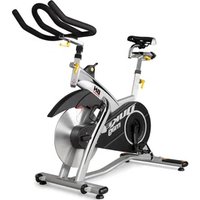
H106 - Exercise bike BH FITNESS - Free user manual and instructions
Find the device manual for free H106 BH FITNESS in PDF.
Frequently Asked Questions - H106 BH FITNESS
User questions about H106 BH FITNESS
0 question about this device. Answer the ones you know or ask your own.
Ask a new question about this device
Download the instructions for your Exercise bike in PDF format for free! Find your manual H106 - BH FITNESS and take your electronic device back in hand. On this page are published all the documents necessary for the use of your device. H106 by BH FITNESS.
USER MANUAL H106 BH FITNESS
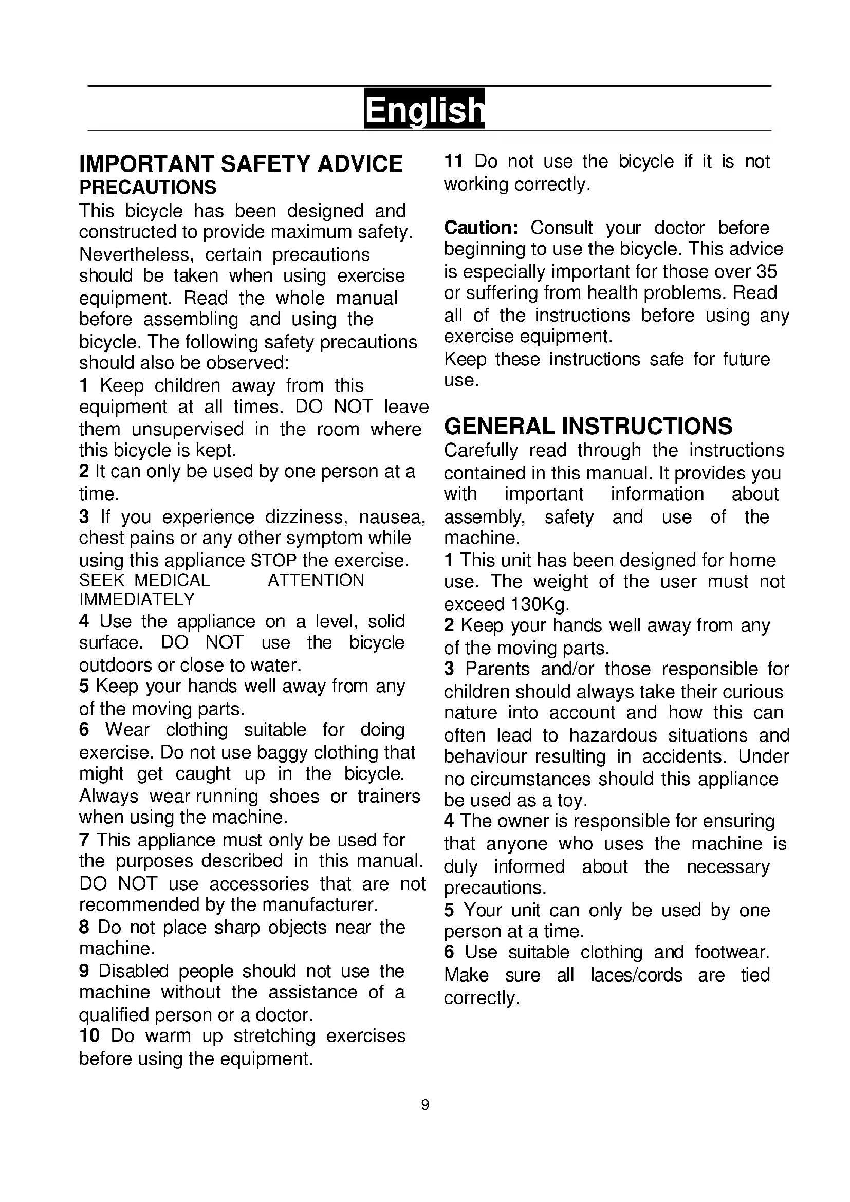
This bicycle has been designed and constructed to provide maximum safety. Nevertheless, certain precautions should be taken when using exercise equipment. Read the whole manual before assembling and using the bicycle. The following safety precautions should also be observed:
1 Keep children away from this equipment at all times. DO NOT leave them unsupervised in the room where this bicycle is kept.
2 It can only be used by one person at a time.
3 If you experience dizziness, nausea, chest pains or any other symptom while using this appliance STOP the exercise. SEEK MEDICAL ATTENTION IMMEDIATELY
4 Use the appliance on a level, solid surface. DO NOT use the bicycle outdoors or close to water.
5 Keep your hands well away from any of the moving parts.
6 Wear clothing suitable for doing exercise. Do not use baggy clothing that might get caught up in the bicycle. Always wear running shoes or trainers when using the machine.
7 This appliance must only be used for the purposes described in this manual. DO NOT use accessories that are not recommended by the manufacturer.
8 Do not place sharp objects near the machine.
9 Disabled people should not use the machine without the assistance of a qualified person or a doctor.
10 Do warm up stretching exercises before using the equipment.
11 Do not use the bicycle if it is not working correctly.
Caution: Consult your doctor before beginning to use the bicycle. This advice is especially important for those over 35 or suffering from health problems. Read all of the instructions before using any exercise equipment.
Keep these instructions safe for future use.
GENERAL INSTRUCTIONS
Carefully read through the instructions contained in this manual. It provides you with important information about assembly, safety and use of the machine.
1 This unit has been designed for home use. The weight of the user must not exceed 130Kg .
2 Keep your hands well away from any of the moving parts.
3 Parents and/or those responsible for children should always take their curious nature into account and how this can often lead to hazardous situations and behaviour resulting in accidents. Under no circumstances should this appliance be used as a toy.
4 The owner is responsible for ensuring that anyone who uses the machine is duly informed about the necessary precautions.
5 Your unit can only be used by one person at a time.
6 Use suitable clothing and footwear. Make sure all laces/cords are tied correctly.
ASSEMBLY INSTRUCTIONS
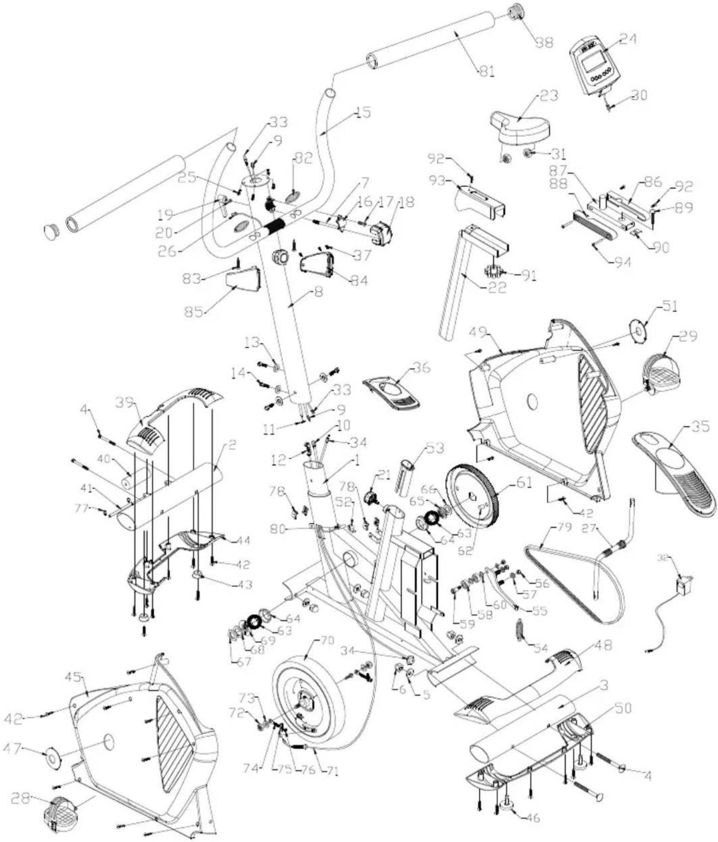
Take the unit out of its box and make sure that all of the pieces are there Fig.1.
1.(1) Main body; (8) Handlebar stem; (22) Saddle post; (23) Saddle; (15) Handlebar; (24) Monitor; (3) Rear stabiliser bar; (2) Front stabiliser bar; a box containing the following: (4) Slot head bolts M-10; (5) Curved washer M-10; (6) Cap nut M-10; (13) Curved washer M-8; (14) Allen screw; (16) handlebar bracket, (17) screw M8; (18) Bracket cover; (19) Handlebar lever; (20) Flat washer M-8; (21) Saddle post knob; (36) Allen key; (37) Double ended ring spanner; (38) Pedal spanner; (28) Left pedal; (29) Right pedal.
- Take the rear stabiliser bar (3) and position it on the machine's rear stand bracket, as shown in Fig.2, inserts bolts (4), fit the curved washers (5) the cap nuts (6) and tighten securely. Take the front stabiliser bar with wheels (2) and position it so that the two red dots (A) line up, as shown in Fig.2, insert bolts (4), fit the curved washers (5) the cap nuts (6), and tighten securely.
FITTING THE HANDLEBAR
Bring the handlebar (15) up to the handlebar stem (8), Fig.3, insert the hand-grip cable (26) in through the slot as shown in Fig.3A and 3B, and pull it out through the top of the handlebar stem. Fit the handlebar bracket (16), insert screw (17) and hand tighten, put the washer (20) on and the handlebar lever (19), position the handlebar and tighten gently, then fit the bracket cover (18).
FITTING THE MONITOR
Mod H-105.- Take the monitor (24) and remove the four screws (25) from the base of the monitor, Fig.4A, connect the terminals for the feedback cables (30) coming out of the monitor to the cable (9) sticking up out of the handlebar stem, Fig.4. Plug the terminal (26) which is also sticking out of the handlebar stem into the hole (26) on the base of the monitor, then plug the terminal (33) which is also sticking out of the handlebar stem into the hole (33) on the base of the monitor. Position the monitor on the handlebar stem, making sure not to catch any of the cables, and attach it using the four screws (25) removed previously.
Mod H-106 Program.- Take the monitor (24), remove the four screws (25) from the base, Fig.4B, connect the terminal coming out of the monitor (12) with the terminal for the cable (9) coming out of the handlebar stem (8), next plug terminal (26) which is also sticking up from the handlebar stem into terminal (35), position the monitor on the handlebar stem, making sure not to catch any of the cables, and attach it using the four screws (25) removed previously.
FITTING THE HANDLEBAR STEM
Mod. H-105.- Hold the handlebar stem (8) and connect the feedback cable terminals (9) and (10) and the terminals (33) and (34), Fig.5. Take the tension cable (11) from the handlebar stem (8) and connect it to the bottom tension support (12), as shown in Fig.5A.
Insert the handlebar stem (8) onto the boss on the main body (1) in the direction of the arrow, making sure not to catch any of the cables, and check that the tension control (100) works correctly. Next, line up the handlebar stem with the holes and fit the 3 Allen screws (14) and the curved washers (13), tighten securely.
Mod. H-106 Program.- Hold the handlebar stem (8). Pass the feedback cable terminals (9) through the handlebar stem using the supplied cable, Fig.5B.
Insert the handlebar stem (8) onto the boss on the main body (1) in the direction of the arrow, making sure not to catch any of the cables. Next, line up the handlebar stem with the holes and fit the 3 Allen screws (14) and the curved washers (13), tighten securely.
ATTACHING THE SADDLE
Place the saddle (23) onto the saddle post (22), as shown in Fig.6, bearing in mind that the holes on the saddle post go at the front section of the saddle, position the saddle correctly and tighten nuts (24) securely. Now insert the saddle post into the hole on the main body (1), fit the saddle post knob (21) and adjust the height of the saddle and tighten it into position by turning the saddle post knob (21) clockwise.
ADJUSTING THE SADDLE HEIGHT
Loosen the saddle post knob (21) a little, turning it anticlockwise, and pull it back, Fig.6, adjust the height of the saddle to suit the exercise and then release the knob so that it slots back into one of the holes on the saddle post.
Tighten the knob (21) securely by turning it clockwise.
FITTING THE PEDALS
The assembly instructions for the pedals must be followed to the letter, fitting these incorrectly could damage the screw thread on either the pedal or the crank.
Right and left refer to the position that the user adopts when sitting on the saddle to do the exercises.
The right-hand pedal (29), marked with the letter (R), screws onto the right-hand crank, also marked with an (R), in a clockwise direction. Tighten securely, Fig.7.
The left-hand pedal (28), marked with the letter (L), screws onto the left-hand crank, also marked with an (L), in an anti-clockwise direction. Tighten securely, Fig.7.
Once the pedals have been fitted, insert the end of the pedal clip (A) into the slot on the pedal (B) adjusting it to your footwear on the ledge of the pedal (C), Fig.7A.
EXERTION SETTINGS.
Mod. H-105.- To provide an even level of exertion during exercise, this appliance is equipped with a tensioning control (100), located on the handlebar stem, offering various exertion settings, Fig.7.
To increase pedal resistance turn the tensioning control (100) clockwise (+) until the exertion level best suits your exercise requirements. To reduce pedal resistance turn the tensioning control (100) anticlockwise (-).
LEVELLING.
Once the unit has been placed into its final position, make sure that it sits flat on the floor and that it is level. This can be achieved by screwing the adjustable feet (7) up or down, as shown in Fig.8.
MOVEMENT & STORAGE
The unit is equipped with wheels (40) to make it easier to move. The wheels located at the front of your unit make it easier to move it into a chosen position, by lifting the rear of the unit up slightly and pushing it, as shown in Fig.9. Store your unit in a dry place, preferably not subject to changes in temperature.
MAINS CONNECTION
Transformer:
12 V- 1000 mAmp.
Insert the jack (g) on the transformer (c) into the connection hole (h) on the main body (A) (bottom, rear of the machine) and then plug the transformer into a 220 V mains supply, Fig.10.
BH RESERVES THE RIGHT TO MODIFY THE SPECIFICATIONS OF ITS PRODUCTS WITHOUT PRIOR NOTICE.
Do not hesitate to get touch with us if you have any queries, by calling:
+44 0844 335 3988
service@bh-uk.co.uk
François
IMPORTANT CONSIGNES DE SECURITE PRECAUTIONS
service@bhfitness.es
Deutsch
service@bhfitness.es
Portugues
AVISO IMPORTANTE DE SEGURANCA PRECAUÇÉS
service@bhfitness.es
Italiano
AVVERTIMENTO IMPORTANT DI SICUREZZA PRECAUZIONI
service@bhfitness.es
Nederlandse
BELANGRIJKE VEILIGHEIDSVOORSCHRIFTEN VOORZORGSGMAATREGELEN
VERPLAATSING EN OPBERGEN
service@bhfitness.es
H-105
To order replacement parts:
State the machine model Corresponding parts n' Quantity
To order replacement parts:
State the machine model Corresponding parts n Quantity
Toll free: +1 866 325 2339
No.139, Jhongshan Rd.
Daya Township
Taichung 428, Taiwan. R.O.C.
Tel.: +886 4 25609200
Fax: +886 4 25609280
e-mail: info@bhfitness.pt
BH SERVICE PORTUGAL
e-mail: info@bhfitness.pt
BH FITNESS MEXICO
BH Exercycle de Mexico S.A. de
CV
Eje 132/136
Zona Industrial, 2A Secc.
78395 San Luis Potosí
S:L:P: MÉXICO
Tel.: +52 (444) 824 00 29
Fax: +52 (444) 824 00 31
www.bh.com.mx
BH FITNESS CHINA
BH China Co., Ltd.
Block A, NO.68, Branch Lane
455,Lane 822,
Zhen Nan RD., Li Zi Yuan,
Putuo, Shanghai 200331, P.R.C.
Tel: +86-021-5284 6694
Fax:+86-021-5284 6814
e-mail: info@i-bh.cn
BH FITNESS FRANCE
27 bis, Route de Pitoys
64600 ANGLET
Tel.: +33 05 59 42 04 71
Fax: +33 05 59 50 10 83
e-mail:
bhfrance@bhfitness.com
SAV FRANCE
Tél: +33 0810 000 301
Fax: +33 0810 00 290
e-mail:
savfrance@bhfitness.com
BH FITNESS UK
Halliards, Terrington Drive
Newcastle-under-Lyme
Staffordshire ST5 4NB
United Kingdom
SPECIFICATIONS MAY BE CHANGED WITHOUT PRIOR NOTICE DUE TO OUR PROGRAMME OF CONTINUOUS PRODUCT DEVELOPMENT.
BH SE RÉSERVE LE DROIT DE MODIFIER LES SPECIFICATIONS DE SES PRODUITS SANS PREAVIS.