ProMatic 2 - Garage door Hormann - Free user manual and instructions
Find the device manual for free ProMatic 2 Hormann in PDF.

Frequently Asked Questions - ProMatic 2 Hormann
User questions about ProMatic 2 Hormann
0 question about this device. Answer the ones you know or ask your own.
Ask a new question about this device
Download the instructions for your Garage door in PDF format for free! Find your manual ProMatic 2 - Hormann and take your electronic device back in hand. On this page are published all the documents necessary for the use of your device. ProMatic 2 by Hormann.
USER MANUAL ProMatic 2 Hormann
natural_image
Technical illustration of a mechanical housing component with mounting brackets and internal slots (no text or symbols)TR10A033-E RE/03.2010
Instructions for Fitting, Operating and Maintenance
text_image
Technical diagram showing exploded view of mechanical components and their assembly with labeled parts A through G.B
text_image
13 mm 10 mm 2 3 mm 4 mm Ø 10 mm Ø 5 mmDEUTSCH 4
ENGLISH 22
FRANÇAIS 39
NEDERLANDS. 58
ESPAÑOL.... 76
ITALIANO.... 95
PORTUGUÊS. 114
133
Inhaltsverzeichnis
natural_image
Pure diagram of a curved structural component without any text, numbers, or symbolsa = Sectionaltor
natural_image
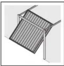
Simple line drawing of a metal frame structure with diagonal slats (no text or symbols)b = Schwingtor
HINWEIS:
text_image
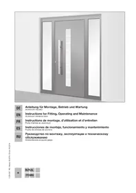
STOP STOPA Articles supplied 2
B Tools needed for assembly 2
1 About These Instructions 23
1.1 Further applicable documents 23
1.2 Warnings used 23
1.3 Definitions used 23
1.4 Symbols used 23
1.5 Abbreviations used 24
2 ⚠ Safety Instructions ...... 24
2.1 Intended use 24
2.2 Non-intended use 24
2.3 Fitter qualification 24
2.4 Safety instructions for fitting,
maintenance, repairs and
disassembly of the door system .... 24
2.5 Safety instructions for fitting 24
2.6 Safety instructions for initial start-up and for operation 25
2.7 Safety instructions for using the hand transmitter.... 25
2.8 Approved safety devices 25
2.9 Safety instructions for inspection and maintenance 25
3 Fitting 25
3.1 Inspect door/door system 25
3.2 Clearance required.... 25
3.3 Fitting the garage door operator 26
3.4 Fitting the operator boom 26
3.5 Fixing the warning sign 27
3.6 Garage door operator electrical connection ..... 27
3.7 Connecting additional components/accessories.... 27
4 Putting into Service 28
4.1 Putting the operator into service 28
4.2 Setting additional functions via the DIL switches 29
5 Radio 31
5.1 Hand transmitter HSM 4 31
5.2 Integral radio module 32
5.3 External receiver 32
5.4 Excerpt from the declaration of conformity for the receiver 32
6 Operation 32
6.1 Instructing users 33
6.2 Function check 33
6.3 Normal operation 33
6.4 Manual operation 33
6.5 Operating after a mechanical release 33
6.6 Behaviour during a power failure (without emergency battery) 34
6.7 Behaviour following a power failure (without emergency battery) 34
6.8 Mains failure bridging using an emergency battery 34
6.9 Operator light messages.... 34
6.10 Error messages/diagnostic LED 34
7 Inspection and Maintenance 35
7.1 Replacement bulb 35
8 Optional Accessories 35
9 Dismantling and Disposal 35
10 Warranty Conditions 35
10.1 Performance 36
11 Excerpt from the Declaration of Incorporation 36
12 Technical Data 36
13 Overview of DIL Switch Functions 37
14 Overview of Errors and Error Elimination ..... 38
Illustrated Section 133
Dissemination as well as duplication of this document and the use and communication of its content are prohibited unless explicitly permitted. Noncompliance will result in damage compensation obligations. All rights reserved in the event of patent, utility model or design model registration. Subject to changes.
Dear customer,
We are delighted that you have chosen a high-quality product from our company.
About These Instructions1
These instructions are original operating instructions as outlined in the EC Directive 2006/42/EC. Read through all of the instructions carefully, as they contain important information about the product. Pay attention to and follow the instructions provided, particularly the safety instructions and warnings.
Please keep these instructions in a safe place and make sure that they are available to all users at all times.
Further applicable documents1.1
The following documents for safe handling and maintenance of the door system must be placed at the disposal of the end user:
These instructions•
The enclosed•
The instructions of the garage door•
Warnings used1.2

The general warning symbol indicates a danger that is to injury or death. In the text, the general warning will be used in connection with the caution levels needed below. In the illustrated Section, an additional question refers back to the explanation in the text.

DANGER
Indicates a danger that leads directly to death or serious injuries.

WARNING
Indicates a danger that can lead to death or serious injuries.

CAUTION
Indicates a danger that can lead to minor or moderate injuries.
ATTENTION
Indicates a danger that can lead to damage or destruction of the product.
Definitions used1.3
Hold-open phase
Waiting phase at the OPEN end-of-travel position before the door closes during automatic timed closing
Automatic timed closing
Automatic timed closing of the door after a set time has elapsed and after reaching the OPEN end-of-travel position.
DIL switches
Switches on the control print for setting the control.
Impulse control
With each push of the button, the door is started against the previous direction of travel, or the motion of the door is stopped.
Force learning cycle
A learning run during which the necessary forces for moving the door are taught in.
Photocell
When actuating the photocell safety device during the movement in the CLOSE direction, the door stops and reverses. The hold-open phase is re-started.
Normal operation
Door movement with the taught-in travel distances and forces.
Reference run
Door cycle towards the OPEN end-of-travel position in order to set the home position.
Reverse cycle/safety reversal
Door travel in the opposite direction when the safety device or force limit is activated.
Reversal limit
If the safety equipment is activated, gate travel is triggered in the opposite direction (reverse cycle) up to the reversal limit (max. 50 mm) shortly before the CLOSE end-of-travel position. If this limit is passed, no reversal occurs to ensure that the gate reaches the end-of-travel position without disrupting travel.
Distance learning cycle
Door cycle with which the operator is taught the path of travel.
Pre-warning time
The time between the travel command (impulse) and the start of travel.
Factory reset
Resetting the taught-in values to the delivery status/ex factory setting
Symbols used1.4
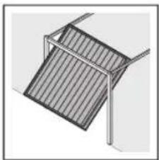
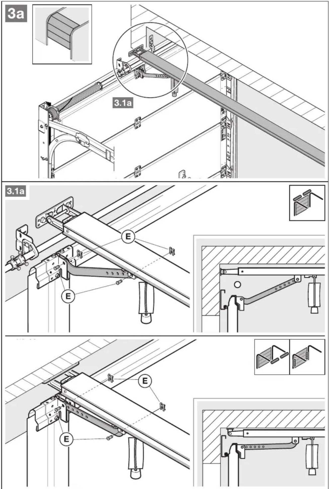
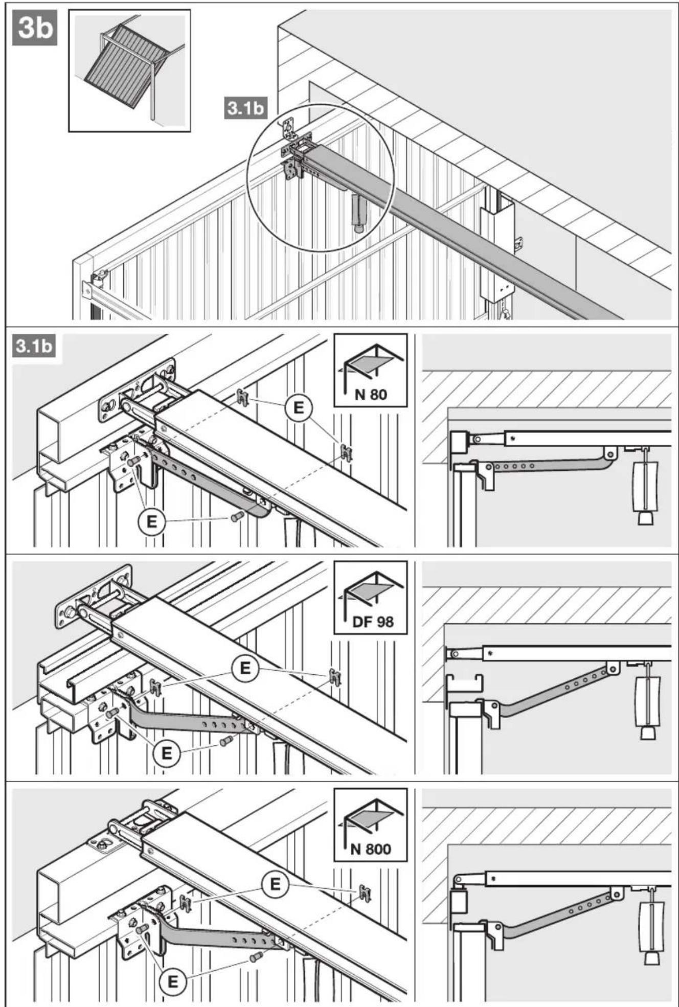
The illustrated Section shows how to fit an operator on a Sectional door. Deviations for fitting with an up-and-over door are also shown. For this purpose, the following letters are assigned to the Figures:
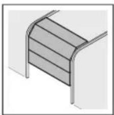
natural_image
Pure diagram of a curved structural component without any text, numbers, or symbolsa = Sectional door
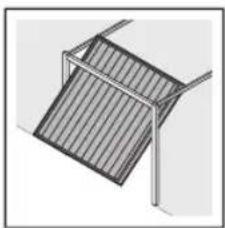
natural_image
Simple line drawing of a geometric structure with diagonal lines and a vertical frame (no text or symbols)b = Up-and-over door
NOTE:
All dimensions in the illustrated Section are in [mm].
Some Figures include this symbol with a reference to a Section of the text. There you will find important information on the fitting and operation of the garage door operator. In the example, 2.2 means:

See text Section 2.2
In addition, in both the text Section and the illustrated Section at the points where the menu of the operators are explained, the following symbol is shown that indicates the factory settings:

Factory setting
Abbreviations used1.5
| Colour code for cables, single conductors and componentsThe abbreviations of the colours for identifying the cables, conductors and components comply with the international colour code according to IEC 757: | |||
| BN Brown WH | White | ||
| GN Green YE | Yellow | ||
| Article designations | |||
| HE 1 1-channel receiver | |||
| IT 1 Internal push button with | impulse button | ||
| IT 1b Internal push button with | illuminated impulse button | ||
| EL 101 One-way photocell | |||
| EL 301 One-way photocell | |||
| STK Wicket door contact | |||
| PR 1 Option relay | |||
| HSM 4 4-button mini hand | transmitter | ||
| HNA 18 Emergency battery | |||
2 ⚠ Safety Instructions
2.1 Intended use
The garage door operator is intended exclusively for the impulse operation of spring-compensated Sectional and up-and-over garage doors in the private/non-commercial sector.
Note the manufacturer's specifications regarding the door and operator combination. Potential hazards as outlined in DIN EN 13241-1 are prevented by the design itself and by carrying out fitting in accordance with our guidelines. Door systems that are located in a public area and only have one protective device, such as a force limit, may only be operated under supervision.
The garage door operator is designed for operation in dry areas.
2.2 Non-intended use
Use in the commercial sector is prohibited.
The operator must not be used for doors without a catch safety device.
2.3 Fitter qualification
Only correct fitting and maintenance in compliance with the instructions by a competent/specialist company or a competent/qualified person ensures safe and flawless operation of the system. According to EN 12635, a specialist is a person with suitable training, specialist knowledge and practical experience sufficient to correctly and safely fit, test, and maintain a door system.
2.4 Safety instructions for fitting, maintenance, repairs and disassembly of the door system

DANGER
Compensating springs are under high tension
▶ See warning in Section 3.1
Fitting, maintenance, repairs, and disassembly of the door system and garage door operator must be performed by a specialist.
In the event of a failure of the garage door operator, a specialist must be commissioned immediately for the inspection or repair work.
2.5 Safety instructions for fitting
The specialist must ensure that the applicable regulations on occupational safety, as well as the regulations on the operation of electrical devices, are followed during assembly work. In the process, the relevant national guidelines must be observed. Potential hazards as outlined in DIN EN 13241-1 are prevented by the design itself and by carrying out fitting in accordance with our guidelines.
The garage door operator is designed for operation in dry areas and therefore must not be fitted outdoors. The garage ceiling must guarantee secure fastening of the operator. For ceilings which are too high or too light, the operator must be fastened on additional struts.
 | DANGER |
| Mains voltage | |
| See warning in Section 3.6 | |

WARNING
Unsuitable fixing material
▶ See warning in Section 3.3
Danger to life from the rope
▶ See warning in Section 3.3
Danger of injury due to unwanted door travel
▶ See warning in Section 3.3
Safety instructions for initial start-up and for 2.6 operation

WARNING
Danger of injury during door travel
▶ See warning in Section 4

CAUTION
Danger of crushing in the side guide
▶ See warning in Section 4
Danger of injury from the cord knob
▶ See warning in Section 4
Danger of injuries due to the hot lamp
▶ See warning in Section 4, Section 6 and Section 7.1
Danger of injury due to the force value being set too high
▶ See warning in Section 4.1.3
Danger of injury resulting from uncontrolled door movement in the CLOSE direction if the torsion spring breaks and the slide carriage is released.
▶ See warning in Section 3.4.1 and Section 6
Safety instructions for using the hand 2.7 transmitter

WARNING
Danger of injury during door travel
▶ See warning in Section 5.1

CAUTION
Danger of injuries due to unwanted door travel
▶ See warning in Section 5.1
Approved safety devices2.8
Safety relevant functions or components of the control, such as the power limit, external photocells, when installed, have been designed and approved in accordance with category 2, PL "c" of EN ISO 13849-1:2008.

WARNING
Danger of injuries due to faulty safety equipment
▶ See warning in Section 4.1.2
Safety instructions for inspection and 2.9 maintenance

WARNING
Danger of injury due to unexpected gate travel
▶ See warning in section 7
Fitting3
3.1 Inspect door/door system

DANGER
Compensating springs are under high tension
Serious injuries may occur while adjusting or loosening the compensating springs!
For your own safety, only have a specialist conduct work on the door compensating springs and, if necessary, maintenance and repair work!
▶ Never try to replace, adjust, repair or reposition the compensating springs for the counterbalance of the door or the spring mountings yourself.
▶ Furthermore, inspect the entire door system (joints, door bearings, cables, springs and fastening parts) for wear and possible damage.
▶ Check for the presence of rust, corrosion, and cracks.
A fault in the door system or an incorrectly aligned door may lead to serious injuries!
▶ Do not use the door system if repair or adjustment work must be conducted!
The design of the operator is not suitable nor intended for the opening and closing of sluggish doors, i.e. doors that can no longer be opened or closed manually, or can only be opened/closed manually with difficulty.
The door must be in perfect mechanical condition and balanced, so that it is easy to operate by hand (EN 12604).
Lift the door by approx. one meter and let it go. The door should stay in this position and neither move downward nor upward. If the door does move in either direction, there is a danger that the compensating springs/weights are not properly adjusted or are defective. In this case, increased wear and malfunctioning of the door system can be expected.
▶ Check whether the door can be opened and closed correctly.
The mechanical locking devices of the door that are not needed with a garage door operator must be put out of commission. This especially includes the locking mechanisms of the door lock (see Section 3.3 and Section 3.6).
Change to the illustrated Section for the fitting and initial operation. Observe the respective text Section when you are prompted to by the symbol for the text reference.
Clearance required3.2
The clearance between the highest point of the door and the ceiling (also when opening the door) must be at least 30 mm (see Figures 1.1a/1.1b).
▶ Check this dimension!
If the clearance is smaller, the operator can also be mounted behind the opened door if enough space is available. In such cases, an extended fitting bracket has to be used, which must be ordered separately. In addition, the garage door operator can be arranged up to max. 50 cm off-centre. Exceptions are Sectional doors with a high-lift (high-lift track application H); a special fitting is required for this arrangement. The electrical outlet necessary for the electrical connection should be fitted approx. 50 cm from the operator head. Please check these dimensions!
3.3 Fitting the garage door operator

WARNING
Unsuitable fixing material
Use of unsuitable fixing material may mean that the operator is insecurely attached and could come loose.
The fitter must check that the fitting materials supplied are suitable for the purpose and the intended fitting location.
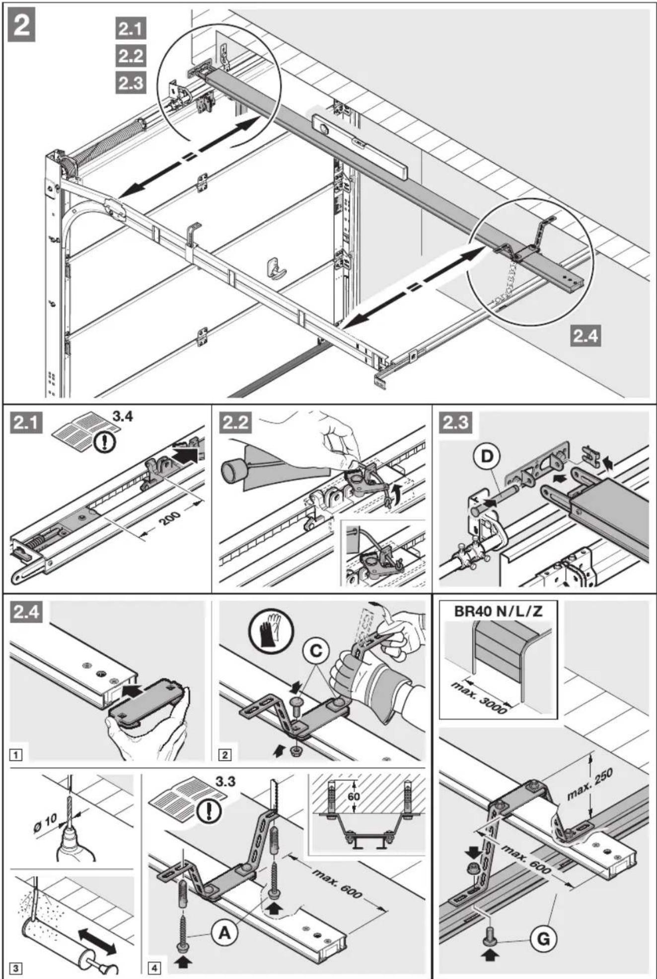
▶ Only use the provided fixing materials (plugs) in concrete ≥ B15 (see Figures 1.6a/1.8b/2.4).

WARNING
Danger to life from the rope
A running rope may lead to strangulation.
Remove the rope while fitting the operator (see Figure 1.2a).

WARNING
Danger of injury due to unwanted door travel
Incorrect assembly or handling of the operator, may trigger unwanted door travel that may result in persons or objects being trapped.
▶ Follow all the instructions provided in this manual.
Incorrectly attached control devices (e.g. buttons) may trigger unwanted door travel. Persons or objects may be trapped as a result.
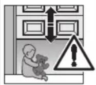
▶ Install control devices at a height of at least 1.5 m (out of the reach of children).
▶ Fit permanently installed control devices (such as buttons, etc.) within sight of the door, but away from moving parts.
ATTENTION
Damage caused by dirt
Drilling dust and chippings can lead to malfunctions.
▶ Cover the operator during drilling work.
NOTE:
An emergency release is necessary for garages without a second entrance that prevents the possibility of being locked out; this must be ordered separately.
▶ Check the emergency release monthly for proper function.
Completely disassemble the mechanical door locking on 1. the Sectional door (see Figure 1.3a).
For Sectional doors with centre door locking, arrange the 2. lintel joint and link bracket off-centre (see Figure 1.5a).
With an off-centre reinforcement profile on the Sectional 3. door, fit the link bracket on the nearest reinforcement profile to the left or right (see Figure 1.5a).
NOTE:
In a deviation from Figure 1.5a: Use the 5 x 35 woodscrews from the door accessory pack (hole ∅ 3 mm) for timber doors.
- The mechanical door locking on an up-and-over door must be rendered inoperable (see Figures 1.3b/1.4b/1.5b). For door models not covered here, block the catches on site.
In a deviation from the Figures 5. 1.6b/1.7b. The lintel joint and link bracket must be attached off-centre for up-and-over doors with ornamental iron door handles.
NOTE:
Use the bottom holes on the lintel joint for fitting N80 doors with timber infill (see Figure 1.7b).
Fitting the operator boom3.4
NOTE:
Before the boom is fitted on the lintel and under the • ceiling, the engaged slide carriage must be moved approx. 20 cm from the CLOSE end-of-travel position in the OPEN direction (see Section 3.4.1). This is no longer possible with an engaged carriage as soon as the end stops and operator have been fitted (see Figure 2.1).
Only use the booms recommended by us for the garage • door operators – depending on the respective purpose of use (see product information)!
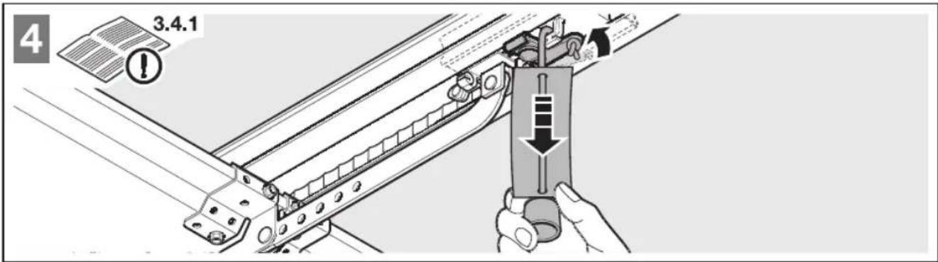
3.4.1 Boom operating modes
There are two different operating modes with the boom:
Manual operation•
Automated operation•
Manual operation
▶ See Figure 4
The slide carriage is disengaged from the belt lock to enable the door to be moved by hand.
For disengaging the slide carriage:
▶ Pull on the cord of the mechanical release.

CAUTION
Danger of injury resulting from uncontrolled door movement in the CLOSE direction if the torsion spring breaks and the slide carriage is released.
The slide carriages may decouple automatically unless a retrofit set is fitted.
The fitter responsible must install a retrofit set on the slide carriage if the following prerequisites are at hand:
- The standard DIN EN 13241-1 applies
- The garage door operator is retrofitted to a Hörmann Sectional door without spring safety device (BR30) by a technical expert.
This set comprises a screw that secures the slide carriage against uncontrolled unlocking as well as a new cord knob sign where the images show how the set and the slide carriage can be handled for the two operating modes of the operator boom.
NOTE:
The use of an emergency release or an emergency release lock is not possible in conjunction with the retrofit set.
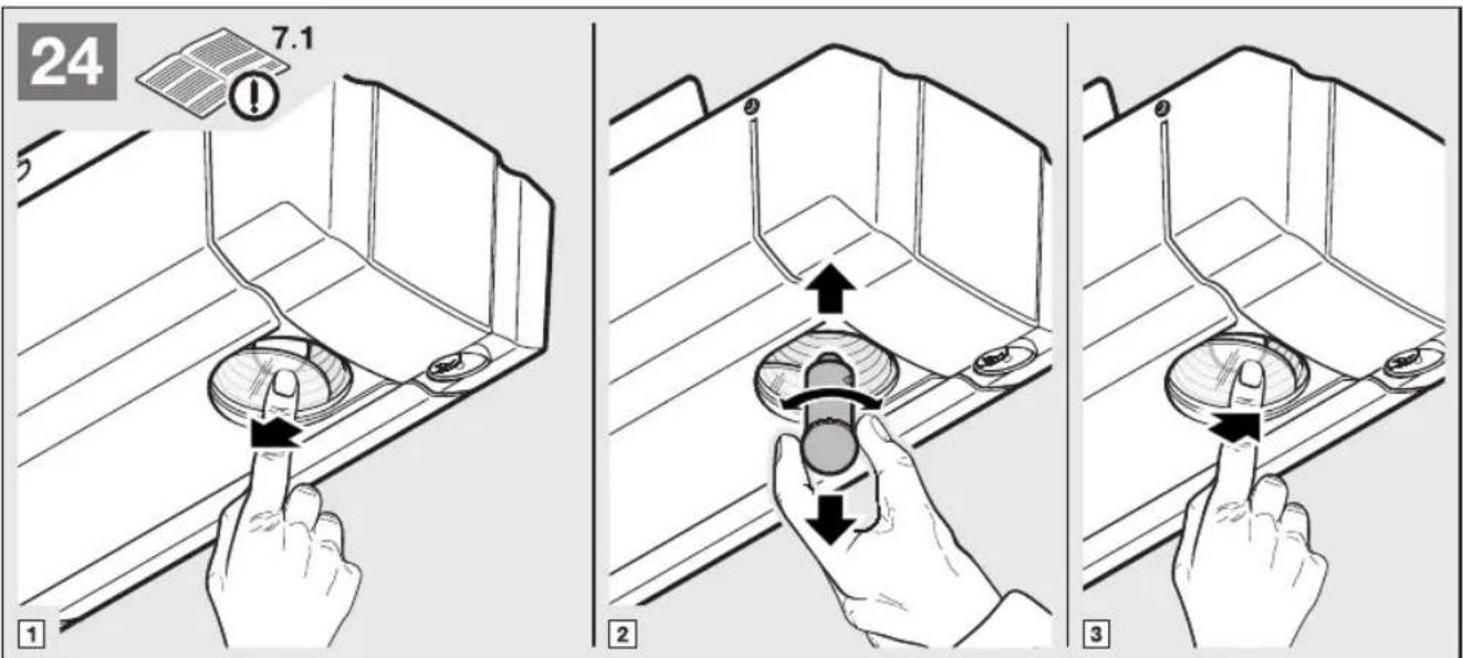
Automated operation
▶ See Figure 6
The belt lock is engaged in the slide carriage to enable the door to be moved with the operator.
For preparing the slide carriage for engaging:
Press the green knob.1.
Move the belt in the direction of the slide carriage until 2. the belt lock engages.

CAUTION
Danger of crushing in the side guide
Do not reach into the side guide with your fingers during door run, as this can cause crushing.
▶ Do not reach into the side guide during the door run
3.6 Garage door operator electrical connection
DANGER
Mains voltage
Contact with the mains voltage presents the danger of a deadly electric shock.
For that reason, observe the following warnings under all circumstances:
Electrical connections may only be made by a qualified electrician.
The on-site electrical installation must conform to the applicable protective regulations (230/240 V AC, 50/60 Hz)!
The mains plug must be disconnected before any work is performed on the operator.
Determining the door end-of-travel positions by 3.4.2 fitting the end stops
- Loosely position the end stop for the OPEN end-of-travel position in the boom between the slide carriage and operator.
- Push the door into the OPEN end-of-travel position by hand.
This will push the end stop into the correct position. - Tighten the end stop for the OPEN end-of-travel position (see Figure 5.1).
NOTE:
If the door should not reach the complete passage height in the OPEN end-of-travel position, the end stop can be removed so that the integrated end stop (in the operator head) is used.
-
Loosely position the end stop for the CLOSE end-of-travel position in the boom between the slide carriage and door.
-
Push the door into the CLOSE end-of-travel position by hand. This will push the end stop near to the correct position.
-
After reaching the CLOSE end-of-travel position move the end stop by approx. 1 cm in the CLOSE direction and fix the end stop (see Figure 5.2).
-
Loosely position the end stop for the CLOSE end-of-travel position in the boom between the slide carriage and door.
- Push the door into the CLOSE end-of-travel position by hand. This will push the end stop near to the correct position.
- After reaching the CLOSE end-of-travel position move the end stop by approx. 1 cm in the CLOSE direction and fix the end stop (see Figure 5.2).
NOTE:
If the door cannot easily be pushed manually into the desired OPEN or CLOSE end-of-travel position, this means that the door mechanism is too stiff for operation with the garage door operator and must be inspected (see Section 1.1.2)!
Tension of the toothed belt3.4.3
The toothed belt of the operator boom is tensioned optimally ex-factory. During the start-up and slow-down phase, with larger doors it is possible that the belt will briefly hang out of the boom profile. However, this does not result in any technical consequences and does not negatively affect the function and service life of the operator.
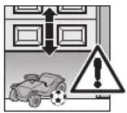
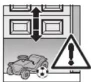
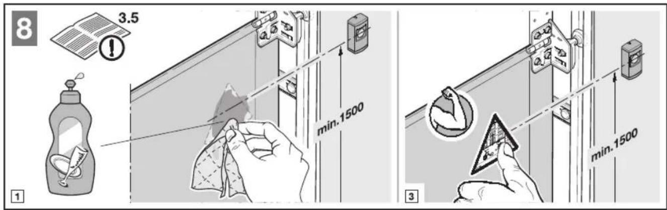
Fixing the warning sign3.5
Fix the sign warning about getting trapped in a noticeable, cleaned and degreased place, for example, near to the permanently installed button for moving the operator.
▶ See Figure 8
ATTENTION
External voltage on the connecting terminals
External voltage on the connecting terminals of the control will destroy the electronics.
Do not apply any mains voltage (230/240 V AC) to the connecting terminals on the control.
To prevent malfunctions:
The connection cables of the operator (24 V DC) must be laid in a separate installation system from the other supply cables (230 V AC).
3.6.1 Electrical connection/connecting terminals
▶ See Figure 9
▶ Remove the plug cover to access the connecting terminals.
NOTE:
All connecting terminals can be assigned several times.
However, observe the following thicknesses (see Figure 10):
• Minimum thickness: 1 x 0.5 mm²
• Maximum thickness: 1 x 2.5 mm ^4
3.7 Connecting additional components/accessories
NOTE:
Loading of the operator by all accessories: max. 100 mA.
3.7.1 External buttons \*
External buttons are used to trigger or stop door cycles. One or more buttons with normally open contacts (volt-free), such as internal push buttons or key switches, can be connected in parallel (see Figure 11/12).
3.7.2 Additional external radio receiver \*
In addition to, or instead of, an integral radio module (see Section 5.2), an external radio receiver can be connected for the impulse function.
▶ Insert the plug of the receiver in the corresponding slot (see Figure 13).
For putting the external receiver into operation, delete the data of an integrated radio module (see Section 5.2.2).
2-wire photocell \*3.7.3
▶ Connect the photocell as shown in Figure 14.
After the photocell triggers, the operator stops and a safety reversal of the door is performed to the OPEN end-of-travel position.
NOTE:
Mount the transmitter and receiver housings as close to the floor as possible – see the instructions for the photocell.
Wicket door contact STK \*3.7.4
Connect the forced opening wicket door contact with self-testing, as displayed in Figure 15.
Door cycles are immediately halted and permanently prevented when the wicket door contact is opened.
Option relay PR 1 \*3.7.5
▶ Connect the option relay, as displayed in Figure 16.
The option relay PR 1 can be used for the CLOSE limit switch reporting and the light control.
Emergency battery HNA 18 \*3.7.6
▶ Connect the emergency battery, as displayed in Figure 22.
To enable door movement in the event of a mains failure, an optional emergency battery can be connected. In the case of a mains failure, the system automatically switches to battery operation. During battery operation, the operator light remains switched off.

WARNING
Danger of injury due to unexpected door travel
Unexpected door travel can result when the emergency battery is still connected despite the mains plug being pulled out.
▶ Disconnect the mains plug and the plug of the emergency battery whenever performing work on the door system.
4 Putting into Service

WARNING
Danger of injury during door travel If people or objects are in the area around the door while the door is in motion, this can lead to injuries or damage.
▶ Children are not allowed to play near the door system.
▶ Make sure that no persons or objects are in the door's travel range.
If the door has only one safety feature, only operate the garage door operator if you are within sight of the door's area of travel.
▶ Monitor the door travel until the door has reached the end-of-travel position.
▶ Only drive or pass through remote control door systems if the door is in the OPEN end-of-travel position!
▶ Never stay standing under the open door.

CAUTION
Danger of crushing in the side guide
Do not reach into the side guide with your fingers during door run, as this can cause crushing.
▶ Do not reach into the side guide during the door run

CAUTION
Danger of injury from the cord knob
If you hang on the cord knob, you may fall and injure yourself. The operator could break away and injure persons or damage objects that are located underneath, or the operator itself could be destroyed.
▶ Do not hang on the cord knob with your body weight.

CAUTION
Danger of injuries due to the hot lamp
Touching the lamp during or immediately following operation can lead to burns.
▶ Do not touch the lamp if it is switched on or was recently switched on.
Putting the operator into service4.1
The operator has a power failure-proof memory in which the door-specific data (travel, forces needed during door travel, etc.) is stored during the teach-in process and updated during subsequent door travels. This data is only valid for this door and must thus be deleted and taught in again for use with another door or if the door's travel behaviour has changed significantly (i.e. in the event of subsequent displacement of the end stops or fitting of new springs, etc.).
4.1.1 Deleting door data
▶ See Figure 18
In the delivery condition, no door data has been stored and the operator can be immediately taught in (see Section 4.1.2).
If it is necessary to teach in again, the door data can be deleted as follows:
Disconnect the mains plug.1.
Push and hold the transparent button in the housing.2.
Connect the mains plug and keep the transparent button 3. in the housing pushed until the operator light flashes once.
The door data are deleted and the operator can be taught in immediately.
4.1.2 Teaching in the operator
Among other things, the travel and forces needed during the opening and closing runs are taught in and saved in a power failure-proof manner during the teach-in process.
NOTES:
Before the operator can be taught in again, the existing • door data must be deleted (see Section 4.1.1).
If connected, the photocell is not active during the • teach-in process.
To teach in the operator:
If necessary, prepare the disengaged slide carriage for 1. engagement by pushing the green button on the slide carriage (see Figure 6). To do this, move the door manually until the slide carriage snaps into the belt lock.
If necessary, plug in the mains plug.2.
The operator light will then flash twice (see Figure 19).
Actuate the transparent button on the operator cover 3. (see Figure 19).
The door will open automatically. The operator light will flash.
Actuate the transparent button on the operator cover 4. again (see Figure 19).
The door will automatically close, open, close and a. then open again. The operator light will flash during the run and the travel and the required forces are taught in.
The door remains in the b. OPEN position and the operator light will then light up continually.
The operator has been taught in and is ready for operation.

WARNING
Danger of injuries due to faulty safety equipment
In the event of a malfunction, there is a danger of injuries due to faulty safety equipment
▶ After the learning runs, the person commissioning must check the function(s) of the safety equipment as well as the settings (see Section 4.2).
The system is ready for operation only after this.
NOTES:
When the operator remains standing with flashing light or the end stops have not been reached, the maximum forces are insufficient and must be readjusted (see Section 4.1.3).
- The teach-in procedure can be interrupted by a run impulse at any time. A further run impulse re-starts the entire teach-in procedure.
4.1.3 Adjusting the forces

CAUTION
Danger of injury due to the force value being set too high (potentiometers P1/P2)
When the force value is set too high, the force limit is less sensitive. This could lead to injury or damage.
▶ Do not set a force value that is too high.
The forces required when teaching-in are readjusted automatically during the subsequent door cycles. For safety reasons, it is necessary that the forces should not be readjusted indefinitely when the travel behaviour of the door becomes worse (e.g. the spring tension weakens). Otherwise risks to safety may arise with manual operation of the door (e.g. the door may fall down).
For this purpose, the maximum forces provided for opening and closing have a limited presetting in delivery condition (centre position of the potentiometers).
When teaching-in the operator (see Section 4.1.2), the forces must be readjusted when one or both end-of-travel positions are not reached.
Two potentiometers are available for this purpose that can be accessed when removing the operator cover (see Figure 20):
• P1: Maximum force in the OPEN direction
• P2: Maximum force in the CLOSE direction
Turning clockwise increases the force, turning anticlockwise reduces the forces.
If the OPEN end stop is not reached:
- Adjust P1 by rotating clockwise by an eighth of a turn (see Figure 20).
- Move the door to the CLOSE end-of-travel position by pressing the transparent button and before reaching the CLOSE end-of-travel position, stop the door by pressing the button again.
- Move the door in the OPEN direction.
If the OPEN end stop is not reached again, repeat steps 1 to 3.
If the CLOSE end stop is not reached:
- Adjust P2 by rotating clockwise by an eighth of a turn (see Figure 20).
- Delete the door data.
- Teach the operator in again (see Section 4.1.2).
If the CLOSE end stop is not reached again, repeat steps 1 to 3.
NOTE:
The maximum forces set in the potentiometer have only little influence on the sensitivity of the force limit, as the actual forces required are saved during the teaching run. The forces set at the factory can be used for operating standard doors.
4.2 Setting additional functions via the DIL switches
Several of the operator's functions must be programmed using the DIL switches. Before initial start-up, the DIL switches are in factory settings, i.e. the switches are in the OFF position (see Figure 9).
NOTE:
Only change the DIL switch settings when the operator is at a rest and no radio codes are being programmed.
Set the DIL switches as described below in accordance with national regulations, the desired safety devices and the on-site conditions.
CLOSE 4.2.1 limit switch reporting: DIL switches A and B
▶ See Figure 17.1
| A OFF | CLOSE limit switch reporting activated |
| B ON |
Function of the operator light and the option relay with Tab. activated CLOSE limit switch reporting
| Operator light Permanent | light during the door • runSwitch-off delay after • CLOSE end-of-travel position |
| Option relay CLOSE limit | switch reporting activated |
Pre-warning time: DIL switch A and B4.2.2
▶ See Figure 17.2
| A ON Pre-warning | time activated |
| B OFF |
Function of the operator light and the option relay with Tab. activated pre-warning time
| Operator light Quick flashing during the pre-• warning timePermanent light during the door • run |
| Option relay Clocks slowly during the door run(function of an auto-flashing warning lamp) |
External illumination: DIL switch A and B4.2.3
▶ See Figure 17.3
| A OFF | External light activated |
| B OFF |
Function of the operator light and the option relay with Tab. external illumination
| Operator light Permanent | light during the door • runSwitch-off delay after • CLOSE end-of-travel position |
| Option relay Same function as operator light | |
Automatic timed closing: DIL switch A, B and D4.2.4
When the door reaches the OPEN end-of-travel position and a hold-open phase of approx. 30 seconds has elapsed, automatic timed closing will start. After an impulse or after the photocell has been passed, the hold-open phase will be extended automatically by approx. 30 s.
NOTES:
- In the scope of the DIN EN 12453, automatic timed closing must only be activated if a safety device is connected.
- Setting the automatic timed closing is only possible if the photocell is active (DIL switch D to ON).
▶ See Figure 17.4
| A ON Automatic | timed closing activated |
| B ON | |
| D ON |
Tab. 4: Function of the operator, the operator light and the option relay with activated automatic timed closing
| Operator | After hold-open phase and pre-warning time, automatic timed closing from the OPEN end-of-travel position |
| Operator light2: | Permanent light during the hold-• open phase and the door run• Flashes during the pre-warning time |
| Option relay | • Permanent contact during the hold-open phase• Clocks rapidly during the pre-warning time and slowly during the door run |
4.2.5 Door type: DIL switch C
▶ See Figure 17.5
| C ON | Up-and-over door, long soft-stop ramp-down phase |
| C OFF | Sectional door, short soft-stop ramp-down phase |
4.2.6 Photocell: DIL switch D
▶. See Figure 17.6
| D ON | Activated, if the photocell is activated, the door reverses to the OPEN end-of-travel position. |
| D OFF | Not activated, automatic timed closing not possible (DIL switch A/B) |
4.2.7 Hold/static current circuit with self-testing: DIL switch E
▶ See Figure 17.7
| E ON | Activated, for wicket door contact with self-testing |
| E OFF | Not activated |
NOTE:
Check safety devices without self-testing every six months.
Door maintenance display: DIL switch F4.2.8
▶ See Figure 17.8
| F ON Activated, | exceeding the maintenancecycle is signalled by the operator lightflashing at the end of every door run. |
| F OFF | Not activated, no signal after themaintenance cycle is exceeded |
The maintenance interval is reached when the operator has been in operation for more than 1 year since the last teaching-in or the operator has reached or exceeded more than 2000 door closing actions.
NOTE:
The maintenance data is reset by teaching-in the operator again (see Section 4.1.2).
5 Radio
5.1 Hand transmitter HSM 4
WARNING
Danger of injury during door travel
Persons may be injured by door travel if the hand transmitter is actuated.
▶ Make sure that the hand transmitters are kept away from children and can only be used by people who have been instructed on how the remote-control door functions!
▶ If the door has only one safety feature, only operate the hand transmitter if you are within sight of the door!
▶ Only drive or pass through remote control door systems if the door is in the OPEN end-of-travel position!
▶ Never stay standing under the open door.
▶ Please note that unwanted gate cycles may occur if a hand transmitter button is accidentally pressed (e.g. if stored in a pocket/handbag).
CAUTION
Danger of injuries due to unwanted door travel
Unwanted door travel may occur while teaching in the radio system.
▶ Pay attention that no persons or objects are in the door's travel range when teaching in the radio system.
ATTENTION
Functional disturbances caused by environmental conditions
These conditions can impair function!
Protect the hand transmitter from the following conditions:
Direct sunlight (perm. ambient temperature: -20^ to +60^ )
Moisture• Dust•
NOTES:
If there is no separate garage entrance, perform all • programming changes and extensions while standing in the garage.
Perform a functional check after programming or • extending the remote control system.
Only use original components for the initial start-up or for • extending the remote control system.
Local conditions may affect the range of the radio • system. Moreover, when used at the same time, GSM 900 mobile phones can affect the range.
Description of the hand transmitter HSM 45.1.1
▶ See Figure 23
1 LED
2 Hand transmitter button
3 Battery compartment cover
4 Battery
5 Reset button
6 Hand transmitter holder
Inserting/changing the battery5.1.2
▶ See Figure 23
▶ Use only the battery type 23A.
5.1.3 Restoring the factory coding
▶ See Figure 23
A radio code is stored for each hand transmitter button. The original factory code can be restored by going through the following steps.
NOTE:
The following steps are only required in the case of inadvertent extension or teach-in processes.
- Open the battery compartment cover. The reset button (5) is accessible on the circuit board.
ATTENTION
Destruction of the button
▶ Do not use any pointed objects or excessive force when pressing the button.
2. Carefully press the reset button with a blunt object and keep it pressed.
3. Press the hand transmitter button to be coded and keep it pressed.
The transmitter LED will flash slowly.
4. If you keep the small button pressed until the slow flashing stops, the hand transmitter button will be assigned with the original factory coding and the LED will start to flash faster.
5. Close the battery compartment cover.
The factory code is now restored.
5.1.4 Excerpt from the declaration of conformity for the hand transmitter
Conformity of the abovementioned product with the requirements of the directives according to article 3 of the R & TTE directives 1999/5/EC was verified by compliance with the following standards:
EN 60950:2000
EN 300 220-1
EN 300 220-3
EN 301 489-1
EN 300 489-3
The original declaration of conformity can be requested from the manufacturer.
5.2 Integral radio module
With an integral radio module, the function Impulse (OPEN-STOP-CLOSE-STOP) function can be taught to a maximum of 6 different hand transmitters. If more than 6 hand transmitters are taught, the functions on the one taught first are deleted.
For programming the radio module or to delete its data, the following conditions must be fulfilled:
The operator is at rest.
The pre-warning or hold-open phase is not active.
NOTES:
For actuating the operator with remote control, a hand • transmitter button must be taught-in to an integral radio module or an external radio receiver.
There must be a distance of at least 1 m between the hand transmitter and the operator.
When used at the same time, GSM 900 mobile phones • can affect the range of the radio remote control.
Teaching in the 5.2.1 Impulse function
Briefly press the 1. P button on the operator cover once (see Figure 21). Pressing the P button again twice will immediately end radio programming.
The red LED in the button on the operator cover now flashes once. During this time, a hand transmitter button can be programmed in for the desired function.
Hold the hand transmitter button that should be 2. programmed down until the red LED in the button on the operator cover begins flashing rapidly.
The radio code of this hand transmitter button is now stored in the integral radio module.
5.2.2 Deleting all data in an integral radio module
Press and hold the 1. P button on the operator cover. The red LED in the button of the operator cover flashes slowly, signalling the readiness for deletion. The flashing then becomes more rapid.
Now the data of all the hand transmitters' learned radio codes is deleted.
- Release the P button on the operator cover.
5.3 External receiver \*
Instead of an integral radio module, an external radio receiver can be used for the Impulse function to control the garage door operator.
5.3.1 Connecting an external receiver
- Insert the plug of an external receiver in the corresponding slot (see Figure 13). The wires of the external receiver must be connected as follows:
- tGNerminal 20 (0 V)
- WH to terminal 21 (channel 1 signal for the impulse control)
- BN to terminal 5 (+24 V)
- Delete the data of an integral radio module to prevent double allocation (see Section 5.2.2).
5.3.2 Teaching in hand transmitter buttons
▶ Impulse function
- Teach in the hand transmitter button for the Impulse function (channel 1) using the operating instructions for the external receiver as a basis.
NOTE:
The aerial wire of the external receiver should not come into contact with metal objects (nails, bracing, etc.). The best orientation to achieve an optimum range must be established by trial and error. When used at the same time, GSM 900 mobile phones can affect the range of the radio remote control.
5.4 Excerpt from the declaration of conformity for the receiver
Conformity of the abovementioned product with the requirements of the directives according to article 3 of the R & TTE directives 1999/5/EC was verified by compliance with the following standards:
EN 60950:2000
EN 300 220-1
EN 300 220-3
EN 301 489-1
EN 300 489-3
The original declaration of conformity can be requested from the manufacturer.
6 Operation
WARNING
Danger of injury during door travel If people or objects are in the area around the door while the door is in motion, this can lead to injuries or damage.
▶ Children are not allowed to play near the door system.
▶ Make sure that no persons or objects are in the door's travel range.
If the door has only one safety feature, only operate the garage door operator if you are within sight of the door's area of travel.
▶ Monitor the door travel until the door has reached the end-of-travel position.
▶ Only drive or pass through remote control door systems if the door is in the OPEN end-of-travel position!
▶ Never stay standing under the open door.
CAUTION
Danger of crushing in the side guide
Do not reach into the side guide with your fingers during door run, as this can cause crushing.
▶ Do not reach into the side guide during the door run

CAUTION
Danger of injury from the cord knob
If you hang on the cord knob, you may fall and injure yourself. The operator could break away and injure persons or damage objects that are located underneath, or the operator itself could be destroyed.
▶ Do not hang on the cord knob with your body weight.

CAUTION
Danger of injury resulting from uncontrolled door movement in the CLOSE direction if the torsion spring breaks and the slide carriage is released.
The slide carriages may decouple automatically unless a retrofit set is fitted.
The fitter responsible must install a retrofit set on the slide carriage if the following prerequisites are at hand: The standard DIN EN 13241-1 applies- The garage door operator is retrofitted to a – Hörmann Sectional door without spring safety device (BR30) by a technical expert.
This set comprises a screw that secures the slide carriage against uncontrolled unlocking as well as a new cord knob sign where the images show how the set and the slide carriage can be handled for the two operating modes of the operator boom.
NOTE:
The use of an emergency release or an emergency release lock is not possible in conjunction with the retrofit set.

CAUTION
Danger of injuries due to the hot lamp
Touching the lamp during or immediately following operation can lead to burns.
▶ Do not touch the lamp if it is switched on or was recently switched on.
ATTENTION
Damage due to the cord of the mechanical release
If the cord of the mechanical release becomes caught on a roof carrier system or anything projecting from the vehicle or door, this can lead to damages.
▶ Make sure that the cord cannot become caught.
Heat generation of the illumination
As a result of heat being generated by the operator light, there is a risk of damage if inadequate spacing is maintained.
The smallest distance to easily inflammable materials or heat sensitive surfaces must be at least 0.1 m (see Figure 7).
Instructing users6.1
▶ Instruct all persons who use the door system on the proper and safe use of the garage door operator.
▶ Demonstrate and test the mechanical release as well as the safety reversal.
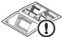
Function check6.2
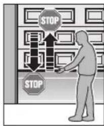
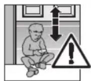
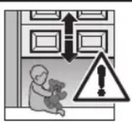
text_image
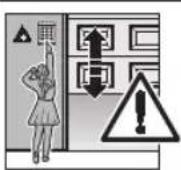
STOP STOPTo check the safety reversal, stop the door with both hands while it is closing. The door system must stop and initiate the safety reversal. The gate system must also switch off and stop the gate while it is opening.
In the event of a failure of the safety reversal, a specialist must be commissioned immediately for the inspection and repair work.
Normal operation6.3
In normal operation, the garage door operator works exclusively according to the impulse sequence control. It does not matter whether an external button, a programmed hand transmitter button or the transparent button has been actuated.
1st impulse: The door runs towards an end-of-travel position.
2nd impulse: The door stops.
3rd impulse: The door runs in the opposite direction.
4th impulse: The door stops.
5th impulse: The door runs in the direction of the end-of-travel position selected in the 1st impulse.
etc.
The operator light will light up during a door run and automatically goes out approx. 2 minutes after the door run ends.
Manual operation6.4
The door must be mechanically released in order to operate it manually. To do this, the slide carriage is disengaged from the belt lock.
To release the door, pull the cord of the mechanical release (see Figure 4).
NOTES:
Inspect the function of the mechanical release monthly. Only pull the cord knob when the door is closed; otherwise, there is a danger that the door will close rapidly if the springs are weak, broken or defective or if the counterbalance is inadequate.
Operating after a mechanical release6.5
If, for example, the mechanical release is actuated due to a mains power failure, the slide carriage must be snapped back into the belt lock to resume normal operation.
Move the operator until the belt lock can be easily 1. reached in the operator boom for the slide carriage.
Push the green button on the slide carriage 2. (see Figure 6).
-
Move the door manually until the slide carriage snaps back into the belt lock.
-
Check whether the door completely reaches its closed position and opens completely by conducting multiple uninterrupted door runs (the slide carriage stops shortly before the OPEN end stop).
Now, the operator is ready for normal operation again.
Behaviour during a power failure 6.6 (without emergency battery)
To be able to open or close the garage door by hand during a power failure, it must be disengaged from the slide carriage.
▶ See Section 3.4.1
Boom operating modes / Manual operation
Behaviour following a power failure 6.7 (without emergency battery)
After the power returns, the slide carriage must be re-engaged.
▶ See Section 3.4.1
Boom operating modes / Automated operation
Mains failure bridging using an emergency 6.8 battery \*
To enable door movement in the event of a mains failure, an optional emergency battery can be connected (see Figure 22). In the case of a mains failure, the system automatically switches to battery operation. During battery operation, the operator light remains switched off.
NOTE:
Only use the original emergency battery with integrated charging circuit.
Operator light messages6.9
If the mains plug is plugged in without the transparent button having been pushed (the circuit board button T when the operator cover has been removed), the operator light will flash two, three or four times.
Two flashes
No door data is present or the door data has been deleted (delivery condition). The operator can be taught in immediately.
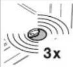
Three flashes
Saved door data is present, but the last door position is not known. For this reason, the next run will be an OPEN reference run. Afterwards, normal door runs will follow.
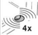
Four flashes
Saved door data is present and the last door position is sufficiently known, i.e. normal door runs that take the impulse sequence control (OPEN-STOP-CLOSE-STOP-OPEN, etc.) into account can proceed immediately (normal behaviour after a successful teach-in and power failure). For safety reasons, the door will always open upon the first impulse command after a power failure during a door run.
Error messages/diagnostic LED6.10
▶ See Figure 9.1
The red diagnostic LED is visible through the transparent button even when the housing is closed. This LED helps to easily identify causes when operation does not go according to plan. In a taught-in condition (normal mode), the LED lights up continually and goes out as long as an externally connected impulse is present.
NOTE:
If normal operation of the garage door operator with the radio module or the transparent button is otherwise possible, a short circuit in the external button's connecting lead or in the button itself can be recognised through the behaviour described here.
| LED Flashes 2xCause PhotocellRemedy Check the photocell and connect or replace if necessary. | was interrupted or is not connected.the photocell and connect or replace if necessary. |
| LED Flashes 3xCause The CLOSE force limit was activated; a safety reversal took place.Remedy Remove the obstruction. If the safety reversal took place for no apparent reason, check the door mechanism. If necessary, delete the door data and teach it in again. | |
| LED Flashes 4xCause The static current circuit or wicket door contact is open or was opened during a door run.Remedy Check the unit connected, close the circuit. | |
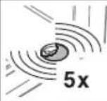
| LED Flashes 5xCause The OPEN force limit has been activated.Remedy Remove the obstruction. If the door stopped before the OPEN end-of-travel position for no apparent reason, check the door mechanism. If necessary, delete the door data and teach it in again. | |
| LED Flashes 6xCause Operator error/malfunction in operator systemRemedy If necessary, delete the door data and teach it in again. If the operator error occurs again, replace the operator. | |
| LED Flashes 7xCause Operator has not been taught in yet.Remedy Initiate a learning run via an external button, the radio module or the transparent button (circuit board button T when the operator cover is removed). | |
| LED Flashes 8xCause The operator requires an OPEN reference run.Remedy Initiate an OPEN reference run via an external button, the radio module or the transparent button (circuit board T button when the operator cover is removed). |
7 Inspection and Maintenance
The garage door operator is maintenance-free.
For your own safety, however, we recommend having the door system checked and maintained by a specialist in accordance with the manufacturer's specifications.

WARNING
Danger of injury due to unexpected gate travel
Unexpected gate travel can result during inspection and maintenance work if the gate system is inadvertently actuated by other persons.
▶ Disconnect the mains plug and, if applicable, the plug of the emergency battery when performing all work on the gate system.
▶ Safeguard the gate system against being switched on again without authorisation.
An inspection or necessary repairs may only be carried out by a qualified person. Contact your supplier for this purpose.
A visual inspection may be carried out by the operator.
▶ Check all safety and protective functions monthly.
▶ Malfunctions and/or defects at hand must be rectified immediately.
7.1 Replacement bulb

CAUTION
Danger of injuries due to the hot lamp
Touching the lamp during or immediately following operation can lead to burns.
▶ Do not touch the lamp if it is switched on or was recently switched on.
To change the bulb:
Close the door1.
Disconnect the mains plug.2.
Allow the bulb to cool3.
Change the 24 V/10 W B(a) 15 s bulb (see Figure 4. 24).
Connect the mains plug.5.
The operator light will flash four times.
Optional Accessories8
Optional accessories are not included in the scope of delivery.
Loading of the operator by all electrical accessories: max. 100 mA.
The following accessories can be connected to the operator:
One-way photocell•
External radio receiver•
External impulse buttons (e.g. key switch)•
Emergency battery for emergency power supply•
9 Dismantling and Disposal
NOTE:
When disassembling, observe the applicable regulations regarding occupational safety.
Have a specialist dismantle the garage door operator in the reverse order of these instructions and dispose of it properly.
10 Warranty Conditions
Warranty
We shall be exempt from our warranty obligations and product liability in the event that the customer carries out his own structural alterations or undertakes improper installation work or arranges for same to be carried out by others without our prior approval and contrary to the fitting guidelines we have provided. Moreover, we shall accept no responsibility for the inadvertent or negligent use of the operator and the accessories nor for improper maintenance of the door and its counterbalance. Batteries and light bulbs are also not covered by the warranty.
Warranty period
In addition to the statutory warranty provided by the dealer in the sales contract, we grant the following warranty for parts from the date of purchase:
- 5 years for the operator mechanics, motor and motor control
- 2 years on radio equipment, accessories and special systems
There is no warranty on consumables (e.g. fuses, batteries, lamps). Claims made under the warranty do not extend the warranty period. For replacement parts and repairs the warranty period is six months or at least the remainder of the warranty period.
Prerequisites
A claim under this warranty is only valid for the country in which the equipment was bought. The product must have been purchased through our authorised distribution channels.
A claim under this warranty exists only for damage to the object of the contract itself. Reimbursement of expenditure for dismantling and fitting, testing of corresponding parts, as well as demands for lost profits and compensation for damages, are excluded from the warranty.
The receipt of purchase substantiates your right to claim under the warranty.
Performance10.1
For the duration of the warranty we shall eliminate any product defects that are proven to be attributable to a material or manufacturing fault. We pledge to replace free of charge and at our discretion the defective goods with non-defective goods, to carry out repairs, or to grant a price reduction.
Damages caused by the following are excluded:
Improper fitting and connection•
Improper initial start-up and operation•
External factors such as fire, water, abnormal • environmental conditions
Mechanical damage caused by accidents, falls, impacts•
Negligent or intentional destruction•
Normal wear or deficient maintenance•
Repairs conducted by unqualified persons•
Use of non-original parts•
Removal or defacing of the data label•
Replaced parts become our property.
Excerpt from the Declaration of 11 Incorporation
(as defined in EC Machinery Directive 2006/42/EC for incorporation of partly completed machinery according to annex II, part B)
The product described on the rear side has been developed, constructed and produced in accordance with the:
EC Machinery Directive 2006/42 EC•
EC Construction Products Directive 89/106/EEC•
EC Low-Voltage Directive 2006/95/EC•
EC Electromagnetic Compatibility Directive 2004/108/EC•
Applied and consulted standards:
• EN ISO 13849-1, PL "c", Cat. 2
Safety of machinery – Safety-related parts of control
systems – Part 1: General principles
• EN 60335-1/2, when applicable
Safety of electrical appliances/Operators for doors
EN 61000-6-3
Electromagnetic compatibility – Electromagnetic radiation
EN 61000-6-2
Electromagnetic compatibility – Interference immunity
Partly completed machinery as defined in the EC Directive 2006/42/EC is only intended to be incorporated into or assembled with other machinery or other partly completed machinery or equipment, thereby forming machinery to which this Directive applies.
This is why this product must only be put into operation after it has been determined that the entire machine / system in which it will be installed corresponds with the guidelines of the EC Directive mentioned above.
12 Technical Data
| Mains voltage | 230/240 V, 50/60 Hz, Stand-by approx. 5 W |
| Protection category | Only for dry rooms |
| Temperature range | -20°C to +60°C |
| Replacement bulb | 24 V / 10 W B(a) 15s |
| Motor | Direct current motor with hall sensor |
| Transformer | With thermal protection |
| Connection | No-screw connection technology for external equipment with 24 V DC low safety voltage, such as internal and external buttons with impulse operation |
| Remote control | Operation with internal or external radio receiver |
| Automatic safety cut-out | Is automatically taught in for both directions separately. Self-learning, wear-free, as it has no mechanical switches. |
| End-of-travel position cut-out force limit | Automatic safety cut-out, readjusting at every door run. |
| Operator boom | Extremely flat (30 mm) With integrated door security kit With maintenance-free, patented toothed belt with automatic belt tensioner |
| Door travel speed | Dependent on door size and weight, approx. 13 cm/s |
| Rated load | See data label |
| Pull and push force | See data label |
| Short-term peak load | See data label |
| Special functions | Operator light, 2-minute light ex factory Stop/off switch can be connected Photocell can be connected Option relay for warning lamp, additional external illumination can be connected Wicket door contact with testing |
| Emergency release | Actuated from inside with pull cord in the event of a power failure |
| Universal fittings | For up-and-over doors and Sectional doors |
| Airborne sound emission of the garage door operator | ≤ 70 dB (A) |
| Use | Exclusively for private garages Not intended for industrial/commercial use |
| Door cycles | See product information |
Overview of DIL Switch Functions13
| DIL A DIL | B Function | Option relay function | ||
| OFF ON | CLOSE limit | switch reporting activated The relay picks up in the | CLOSE end-of-travel position (CLOSE reporting function) | |
| ON OFF | Pre-warning | time activated Relay clocks rapidly during the pre-warning time and normally during the door run (warning lamp function) | ||
| OFF OFF | External light | activated Relay the same as operator light (external light function) |  |
| DIL A DIL | B DIL D F | Function Option relay function | ||
| ON ON ON | Automatic | timed closing activated,photocell must be installed | Relay clocks rapidly during the pre-warning time, normally during the travel phase and has permanent contact during the hold-open phase |
| DIL C Door type | ||
| ON Up-and-over door, long soft-stop ramp-down phase | ||
| OFF Sectional door, short soft-stop ramp-down phase | [505C] | |
| DIL D Photocell | ||
| ON | Photocell is activated, after triggering the photocell, the door reverses to the OPEN end-of-travel position (automatic timed closing is only possible with a photocell) | |
| OFF Photocell not activated (automatic timed closing not possible) |  | |
| DIL E Stop circuit with self testing | ||
| ON Wicket door contact with self-testing activated. The self-testing is checked before each door run (operation only possible with a wicket door contact that can be tested) | ||
| OFF Safety device without self-testing |  | |
| DIL F Door maintenance display | |
| ON Activated, exceeding the maintenance cycle is signalled by the operator light flashing at the end of every door run | |
| OFF Not activated, no signal after the maintenance cycle is exceeded | [ZDAS] |
Overview of Errors and Error Elimination14
| Display Error/warning Possible cause Remedy | |||
 | Safety device Photocell was interrupted, is not connected. Check photocell, replace if necessary. | ||
 | Force limit in CLOSE direction | Obstruction in door area. Remove the obstruction. | ▶ Teach in again if required |
 | Wicket door contact static current circuit | Interrupted wicket door contact. Check the wicket door. | |
 | Force limit in OPEN direction | Obstruction in door area. Remove the obstruction. | ▶ Teach in again if required |
 | Operator error Renewed impulse input by means of an external button, the radio module or the transparent button (circuit board T button when the operator cover is removed) – an opening run will take place (OPEN reference run). | ▶ Delete door data, replace operator if this recurs several times. | |
 | Operator error Message, no fault | The operator has not been taught in yet. Teach in the operator. | |
 | No reference point Power failure | The operator requires a reference run. Reference run in the OPEN direction. | |
Table des matières
natural_image
Simple 3D illustration of a curved structural component with horizontal bands (no text or symbols)natural_image
Simple line drawing of a metal frame structure with diagonal slats (no text or symbols)b = porte basculante
REMARQUE :
▶ Fonction Impulsion
text_image
STOP STOPDirective CE Machines 2006/42/CE•
Directive CE Basse tension 2006/95/CE•
natural_image
Pure diagram of a curved structural component without any text, numbers, or symbolsnatural_image
Simple line drawing of a metal frame structure with diagonal slats (no text or symbols)(b) = kanteldeur
OPMERKING:
text_image
STOP STOPnatural_image
Pure diagram of a curved structural component without any text, numbers, or symbolsa = Puerta seccional
natural_image
Simple line drawing of a geometric structure with diagonal slats and vertical supports (no text or symbols)b = Puerta basculante
INDICACIÓN:
text_image
STOP STOPnatural_image
Simple line drawing of a curved metal bracket or support structure (no text or symbols)natural_image
Simple line drawing of a metal frame with a slanted panel, no text or symbols presentb = portone basculante
NOTA:
text_image
STOP STOPnatural_image
Pure diagram of a curved structural component without any text, numbers, or symbolsa = Porta seccional

natural_image
Simple line drawing of a geometric structure with diagonal slats and vertical supports (no text or symbols)b = Porta basculante
NOTA:
4.1.3 Ajustar as forças
CUIDADO
text_image
STOP STOPtext_image
1.1b N 80 = 50 DF 98 = 85 N 800 = 50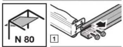
text_image
N 80 1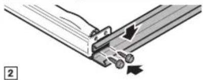
natural_image
Technical diagram of a mechanical assembly with no visible text or symbols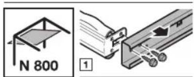
text_image
N 800 1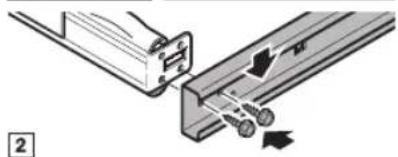
natural_image
Mechanical assembly diagram showing two components connected by a rod, with no visible text or symbols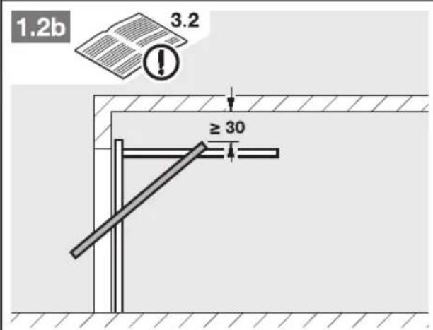
text_image
1.2b 3.2 ≥ 30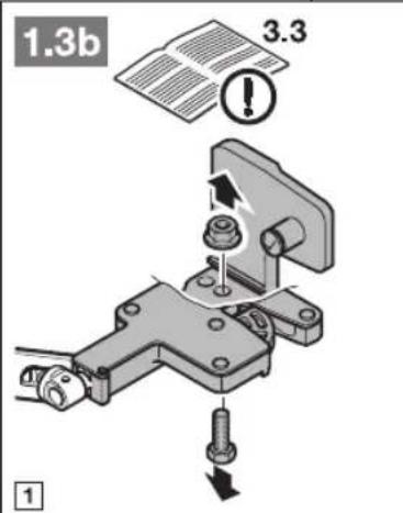
text_image
1.3b 3.3 ! ①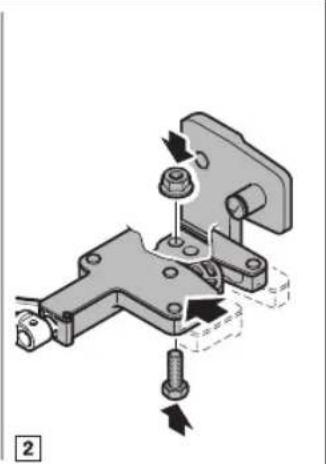
natural_image
Mechanical assembly diagram showing a bracket with bolts and a nut, no text or symbols present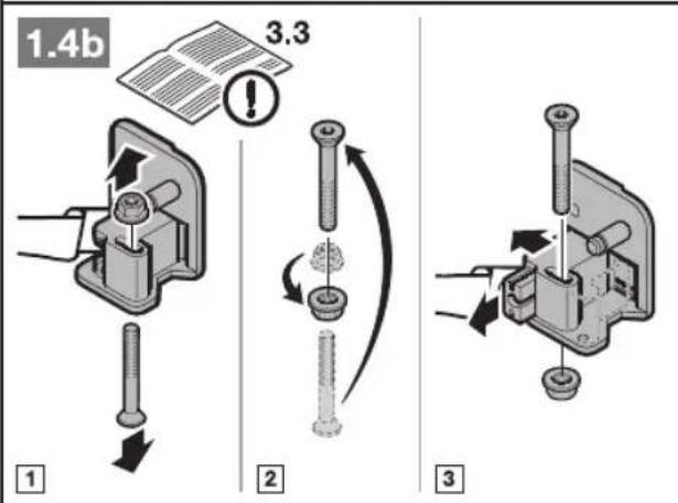
text_image
1.4b 3.3 1 2 3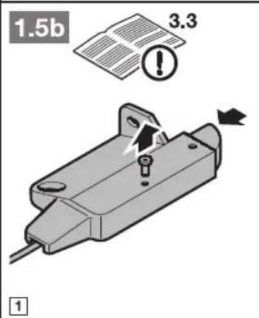
text_image
1.5b 3.3 1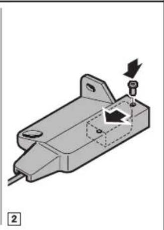
natural_image
Mechanical component diagram showing a housing with a screw and directional arrow (no text or symbols)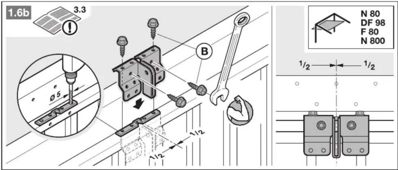
text_image
1.6b 3.3 N 80 DF 98 F 80 N 800 Ø5 B 1/2 1/2 1/2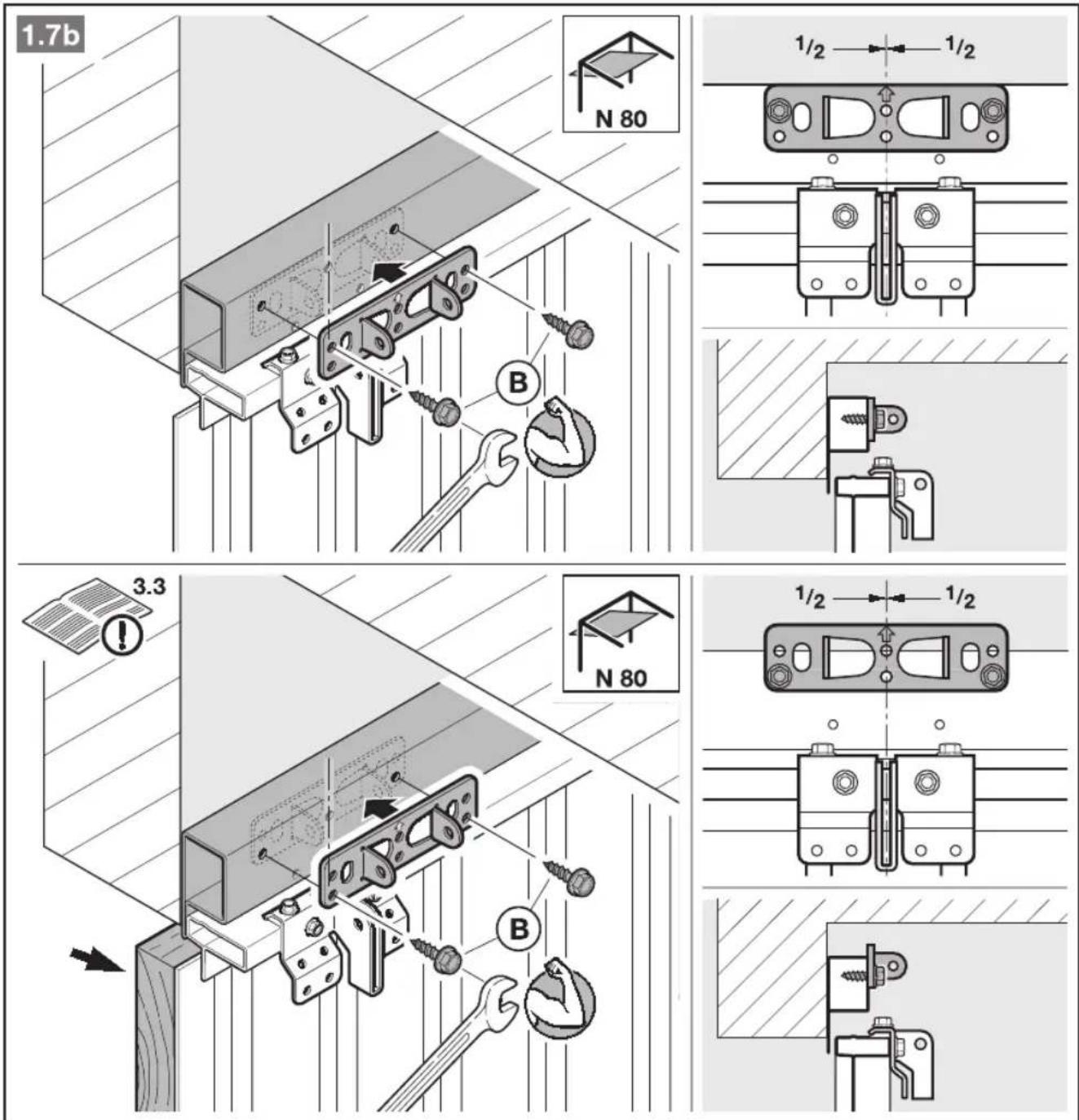
text_image
1.7b N 80 1/2 1/2 3.3 N 80 1/2 1/2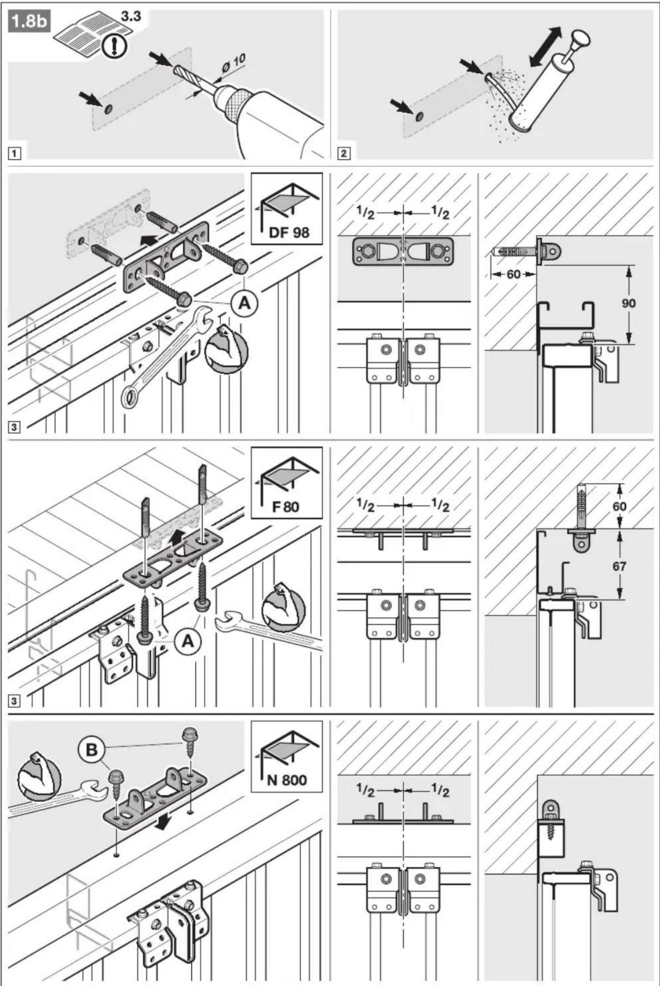
text_image
4 3.4.1
text_image
5.1 3.4.2 1 2 3 4 ≤ 30° 5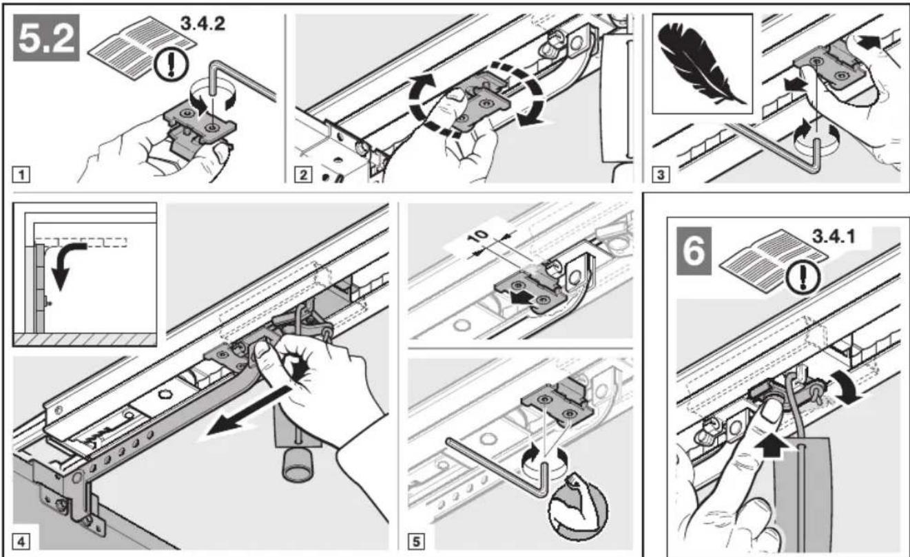
text_image
5.2 3.4.2 1 2 3 4 5 6 3.4.1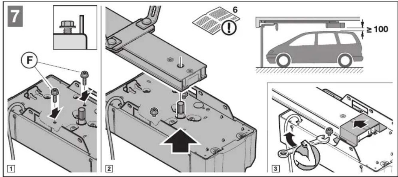
text_image
22 3.7.6/6.8 1 2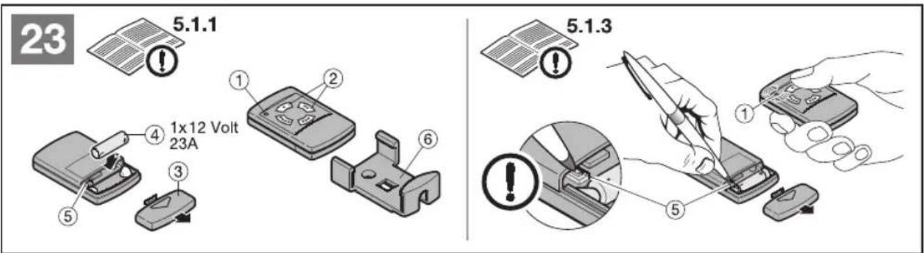
text_image
23 5.1.1 1x12 Volt 23A ① ② ③ ④ ⑤ ⑥ 5.1.3