PortronicD 5000 - Garage door Hormann - Free user manual and instructions
Find the device manual for free PortronicD 5000 Hormann in PDF.

| Product Type | Swing Gate Automation (Garage Door) |
| Brand | Hörmann |
| Model | PortronicD 5000 |
| Max. Leaf Width | 2500 mm |
| Max. Gate Height | 2000 mm |
| Max. Leaf Weight | 200 kg |
| Mains Supply | 230 V / 50 Hz |
| Power Consumption | 0.15 kW |
| Standby Power | Approx. 12 W |
| Radio Frequency | 433 MHz (Rolling Code) |
| Operating Temperature | -20 °C to +60 °C |
| Protection Rating (Control Unit) | IP 65 |
| Protection Rating (Motor) | IP 44 |
| Duty Cycle | S2 (Short-time operation 4 min) |
| Main Functions | Position learning, self-learning force limiter, automatic closing, safety reversal, impulse control, leaf delay (2 leaves), warning lights |
| Safety | Force limiter, photocell (optional), emergency stop, obstacle reversal |
| Maintenance | Maintenance-free motor; monthly visual check of safety functions |
| Included Accessories | RSC 2 transmitter (2 buttons, rolling code) |
| Optional Accessories | RSZ 1 transmitter, RCT 3b keypad, key switch, EL 301 photocell, electric locks, warning lights |
| Warranty | 2 years (excluding consumables) |
| Max. Motor/Control Cable Length | 40 m |
Frequently Asked Questions - PortronicD 5000 Hormann
User questions about PortronicD 5000 Hormann
0 question about this device. Answer the ones you know or ask your own.
Ask a new question about this device
Download the instructions for your Garage door in PDF format for free! Find your manual PortronicD 5000 - Hormann and take your electronic device back in hand. On this page are published all the documents necessary for the use of your device. PortronicD 5000 by Hormann.
USER MANUAL PortronicD 5000 Hormann
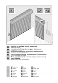
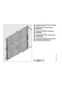
Instructions for Fitting, Operating and Maintenance
Hinged gate operator
Extreme Impuls-Taster (Z. B. Schlüsseltaster)
Lichtschranke
Warnlampe/Signalleuche
| C1 | Hand transmitter RSC 2 (including hand transmitter holder) This hand transmitter works with a rolling code (frequency: 433 MHz) that changes with each sending procedure. The hand transmitter is equipped with two buttons, i.e. you can use the second button to open another gate (double-leaf system). | |
| C2 | Hand transmitter RSZ 1 This hand transmitter is for insertion in a vehicle cigarette lighter. The hand transmitter works with a rolling code (frequency: 433 MHz) that changes with each sending procedure. | |
| C3 | Radio code switch RCT 3b Up to 3 gate operators can be wirelessly operated via impulse using the illuminated radio code switch. This does away with the time-consuming need to lay cables. | |
| C4 | Surface-mounted/reccessed key switch You can use the key switch to operate the hinged gate operator from the outside with a key. Two versions in one device – surface-mounted or recessed. | |
| C5 | Receiver RERI 1 / RERE 1 This 1-channel receiver enables operation of a hinged gate operator with one hundred additional hand transmitters (buttons). Memory spaces: 100 Frequency: 433 MHz (rolling code) Operating voltage: 24 V AC/DC or 230/240 V AC Relay output: On/off | |
| C6 | One-way photocell EL 301 For outside use as additional safety equipment. Including 2 x 10 m connecting lead (2-wire) and fixing material. | |
| C7 | Sound-absorbing seal set DP 21/DP 22 Profile for additional closing edge safety. DP 21 for a max. gate height of 1000 mm, DP 22 for a max. gate height of 2000 mm. Set includes: 1 sound-absorbing seal DP 2 in the appropriate length 1 C-profile in the appropriate length | |
| C8 | Electric lock for post locking | |
| C9 | Electric lock for floor locking | |
| C10 | Stop plate prepared for electric lock can also be used as an end stop. | |
| C11 | Set of base plates for stop plate | |
| C12 | Yellow LED warning light | |
| C13 | Wall bracket for LED warning light |
Table of Contents
A Articles supplied 2
B Tools needed for assembly 2
C Accessories for the hinged gate operator 22
D Spare parts 147
1 About These Instructions 25
1.1 Further applicable documents 25
1.2Warnings used 25
1.3 Definitions used 25
1.4 Symbols and abbreviations used 25
1.5 Abbreviations used 26
2 Safety Instructions 26
2.1 Intended use 26
2.2 Inappropriate use 26
2.3 Fitter qualification 26
2.4 Safety instructions for fitting, maintenance, repairs and disassembly of the gate system 26
2.5 Safety instructions for fitting 26
2.6 Safety instructions for initial start-up and for operation 26
2.7 Safety instructions for using the hand transmitter 26
2.8 Safety instructions for inspection and maintenance 26
2.9 Approved safety equipment 27
3Fitting 27
3.1 Preparation for fitting 27
3.2 Fitting the gate operator 27
3.3 Fitting the operator control 28
3.4 Mains voltage 29
3.5 Connecting the operators 29
4 Initial Start-Up of the Basic Equipment 29
4.1 Single-leaf gate system 29
4.2 Double-leaf gate system 30
4.3 Force learning runs 31
4.4 Connecting the safety device 32
4.5 Connecting additional components/accessories 32
4.6 Setting additional functions via the DIL switches 32
5 Radio 33
5.1 Hand transmitter RSC 2 33
5.2 Integral radio module 34
5.3 External receiver 34
6 Operation 35
6.1 Instructing users 35
6.2 Normal operation 35
6.3 Reversing during an opening run 35
6.4 Reversing during a closing run 35
Dissemination as well as duplication of this document and the use and communication of its content are prohibited unless explicitly permitted. Noncompliance will result in damage compensation obligations. All rights reserved in the event of patent, utility model or design model registration. Subject to changes.
6.5 Behaviour during a power failure 35
6.6 Behaviour following a power failure 35
6.7 Disengaging without a power failure.. 35
6.8 Factory reset 35
6.9 Operation, error and warning messages 35
6.10 Error acknowledgement 36
7 Inspection and Maintenance 36
8 Optional Accessories 36
9 Dismantling and Disposal 36
10 Warranty Conditions 36
11 Excerpt from the Declaration of Incorporation 37
12 Technical Data 37
13 Overview of DIL Switch Functions 38
Illustrated section 133
Dear customer,
We are delighted that you have chosen a high-quality product from our company.
About These Instructions1
These instructions are original operating instructions as outlined in the EC Directive 2006/42/EC. Read through all of the instructions carefully, as they contain important information about the product. Pay attention to and follow the instructions provided, particularly the safety instructions and warnings.
Please keep these instructions in a safe place and make sure that they are available to all users at all times.
Further applicable documents1.1
The following documents for safe handling and maintenance of the gate system must be placed at the disposal of the end user:
These instructions
The enclosed test log book
The gate instructions
Warnings used1.2

The general warning symbol indicates a danger
that can lead to injury or death. In the text, the general warning symbol will be used in connection with the caution levels described below. In the illustrated section, an additional instruction refers back to the explanation in the text.

DANGER
Indicates a danger that leads directly to death or serious injuries.

WARNING
Indicates a danger that can lead to death or serious injuries.

CAUTION
Indicates a danger that can lead to minor or moderate injuries.
ATTENTION
Indicates a danger that can lead to damage or destruction of the product.
Definitions used1.3
Hold-open phase
Waiting phase at the OPEN end-of-travel position before the gate closes during automatic timed closing
Automatic timed closing
Automatic timed closing of the gate after a set time has elapsed and after reaching the OPEN end-of-travel position.
DIL switches
Switches on the control circuit board for setting the control.
Leaf A/traffic leaf
The traffic leaf in double-leaf systems that is opened for pedestrian traffic.
Leaf B/forced leaf
In double-leaf systems, the leaf that is opened and closed along with the traffic leaf to open or close a passage.
Leaf offset
The leaf offset ensures the correct closing order if the fittings overlap.
Impulse control/impulse operation
With each push of the button, the gate is started against the previous direction of travel, or the motion of the gate is stopped.
Force learning run
The forces necessary for gate travel are taught in during this learning run.
Normal cycle
Gate movement with the taught-in travel distances and forces.
Reference run
Gate travel towards the CLOSE end-of-travel position in order to reset the home position (e.g. after a power failure).
Reversing cycle/safety reversal
Gate travel in the opposite direction when the safety equipment or force limit is activated.
Reversal limit
If the safety equipment is activated, gate travel is triggered in the opposite direction (reverse cycle) up to the reversal limit (max. 50~mm ) shortly before the CLOSE end-of-travel position. If this limit is passed, no reversal occurs to ensure that the gate reaches the end-of-travel position without disrupting travel.
Distance learning run
Gate travel with which the operator is taught the path of travel.
Press-and-hold travel
The gate travels only as long as the respective buttons are pressed.
Pre-warning time
The time between the travel command (impulse)/end of the hold-open phase and the start of travel.
Factory reset
Resetting the taught-in values to the delivery status/ex factory setting.
Symbols and abbreviations used1.4
The illustrated section shows how to fit an operator on a single-leaf or double-leaf hinged gate.
NOTE:
All dimensions in the illustrated section are in [mm].
Some figures include this symbol with a reference to a section of the text. There you will find important information on the fitting and operation of the hinged gate operator.
In the example, 2.2 means:
See text section 2.2
In addition, in both the text section and the illustrated section at the points where the operator menus are explained, the following symbol is shown that indicates the factory settings:

Factory setting
Abbreviations used1.5
| Colour code for cables, single conductors and components The abbreviations of the colours for identifying the cables, conductors and components comply with the international colour code according to IEC 757: | |||
| BK Black RD Red | |||
| BN Brown WH White | |||
| GN Green YE Yellow | |||
2 Safet Instructions
Intended use2.1
The hinged gate is designed and intended exclusively for the operation of smooth-running hinged gates in the domestic, non-commercial sector. The maximum permissible gate size and maximum weight must not be exceeded. The gate must be easy to open and close by hand.
Regional wind loads must be taken into account if using gate infills (EN 13241-1).
Note the manufacturer's specifications regarding the gate and operator combination. Potential hazards as outlined in DIN EN 13241-1 are avoided by construction and fitting according to our guidelines.
Gate systems that are located in a public area and only have one protective device, such as a force limit, may only be operated under supervision.
Inappropriate use2.2
Continuous operation and use in the commercial sector is prohibited. The operator is not designed for use with sluggish gates. Use on gates with a gradient or slope is not permitted.
Fitter qualification2.3
Only correct fitting and maintenance in compliance with the instructions by a competent/specialist company or a competent/qualified person ensures safe and flawless operation of the system. According to EN 12635, a specialist is a person with suitable training, specialist knowledge and practical experience sufficient to correctly and safely fit, test, and maintain a gate system.
Safety instructions for fitting, maintenance, 2.4 repairs and disassembly of the gate system

WARNING
Danger of injury due to unexpected gate travel
See warning in section 7
Fitting, maintenance, repairs, and disassembly of the gate system and gate operator must be performed by a specialist.
In the event of a failure of the gate system or the operator, a specialist must be commissioned immediately for the inspection or repair work.
Safety instructions for fitting2.5
The specialist carrying out the work must ensure that installation is conducted in compliance with the prevailing national job safety rules and regulations and those governing the operation of electrical equipment. The relevant national directives must be observed. Potential hazards as outlined in DIN EN 13241-1 are avoided by construction and fitting according to our guidelines.
After fitting has been completed, the installer of the gate system must declare conformity with DIN EN 13241-1 in accordance with the scope of application.
2.6 Safety instructions for initial start-up and for operation
2.7 Safety instructions for using the hand transmitter


2.8 Safety instructions for inspection and maintenance

Approved safety equipment2.9
Safety relevant functions or components of the control, such as the power limit, external photocells, when installed, have been designed and approved in accordance with category 2, PL "c" of EN ISO 13849-1:2008.

WARNING
Danger of injuries due to faulty safety equipment
See warning in section 4.1.5
Fitting3
3.1 Preparation for fitting

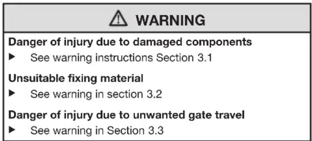
WARNING
Danger of injury due to damaged components
A fault in the gate system or an incorrectly aligned gate may lead to serious injuries!
Do not use the gate system if repair or adjustment work must be conducted!
In addition, check the entire gate system (gate pivots, bearings, springs and fastenings) for wear and possible damage.
Check for the presence of rust, corrosion, and cracks.
For your own safety, only have a specialist conduct maintenance and repair work!
Before installing the operator and in the interests of personal safety, make sure that any necessary repairs to the gate system are carried out by a qualified specialist.
Only correct fitting and maintenance in compliance with the instructions by a specialist company or qualified person ensures safe and flawless operation of the system.
The specialist carrying out the work must ensure that installation is conducted in compliance with the prevailing national job safety rules and regulations and those governing the operation of electrical equipment. The relevant national directives must be observed. Potential hazards are avoided by construction and fitting according to our guidelines.
Prior to fitting, deactivate or completely disassemble any mechanical locks not needed for power operation of the gate. This includes in particular any locking mechanisms connected with the gate lock.
In addition, check that the gate is in a flawless mechanical condition, so that it can be easily operated manually and opens and closes properly (EN 12604).
Change to the illustrated section for the fitting and initial operation. Observe the respective text section when you are prompted to by the symbol for the text reference.
3.2 Fitting the gate operator

WARNING
Unsuitable fixing material
Use of unsuitable fixing material may mean that the operator is insecurely attached and could come loose.
The fitter must check that the fitting materials supplied are suitable for the purpose and the intended fitting location.
Only use the provided fixing materials (plugs) in concrete ≥ B15 (see Figures 2.1/3.1).
NOTE:
Contrary to the illustrated section, use the appropriate connectors with different hole depths for other gate types (e.g. for timber gates use woodscrews).
Contrary to the illustrated section, the required core hole diameter may vary depending on material thickness or strength. The required diameter may be 0.5 - 5.5mm for aluminium and 0.5 - 5.8mm for steel.
Establishing the fitting dimensions3.2.1
Determine dimension e, see Figure1. 1.
Determine dimension B in the table in Figure2. 1:
In column a. e, select the row that is closest to dimension e.
Select the required minimum opening angle in this b. row.
Find dimension B at the top.c.
Fitting principles for complying with the 3.2.2 operating forces
In accordance with DIN EN 12453/12445, the operating forces are complied with if you observe the following points:
In the table in Figure 1, select a combination of dimensions A and B from the section shaded in grey (preferred section).
The centre of gravity for the gate must be in the centre of the gate (maximum permissible deviation ± 20% ).
- A sound-absorbing seal DP 2* with the relevant C-profile is fitted to the closing edge(s).
The operator is programmed for slow travel speed (see section 4.6.2)
- The reversal limit at max. 50mm opening width has been checked and maintained over the entire length of the main closing edge. Otherwise, the A dimension must be increased.
These fitting instructions have been observed.
3.2.3 Fitting principles for a long service life
The operator will have a long service life if the following conditions are met:
- Gate travel is smooth.
The preferred section (see Figure 1) has been selected. - For uniform gate travel speed, dimensions A and B should be as close as possible; do not exceed a max. difference of 40~mm .
The gate travel speed has a direct influence on the resulting forces. They should be kept as low as possible at the gate closing edge(s).
If possible, use the entire spindle stroke
A larger dimension A reduces the speed at the gate closing edge in the CLOSE direction
A larger dimension B reduces the speed at the gate - closing edge in the OPEN direction
Always select a large dimension B if you want a large - gate opening angle. The operator must be programmed for slow speed (see section 4.6.2).
The max. gate opening angle decreases with a larger dimension A.
For a large gate opening angle and/or small A - dimension, the operator must be programmed for slow speed (see section 4.6.2).
To reduce the overall forces on the spindle, dimension A and the distance between the pivot point of the gate and the spindle attachment to the gate must be as large as possible.
NOTES:
Selecting an unnecessarily large opening angle will impair gate travel.
The values indicated in the table in Figure 1 are only guidelines.
Attaching the fittings3.2.4
The fittings provided are galvanized and prepared for aftertreatment.
Stone or concrete posts
Observe the recommendations for plug hole edge distances. For the plugs included in the delivery, the minimum distance is one plug length.
Turn the plugs so that the direction the plug spreads is parallel to the edge.
Adhesive bond anchors, which allow a grub screw to be glued into the brickwork free of tension, offer an even better hold.
For masonry posts, the post bracket should be fitted or welded to a large steel plate that is screwed onto and covers multiple bricks.
An angle plate that goes around the edge of the post is also good for fitting.
Steel posts
Check whether the available support is stable enough. If this is not the case, it must be reinforced.
Using rivet nuts may also be expedient.
The fittings can also be welded on directly.
Wooden posts
The gate hardware must be tightened using through-holes. Use large steel washers or, even better, a steel plate on the rear of the post to ensure that it cannot come loose.
Fitting the operator3.2.5
ATTENTION
Dirt
Drilling dust and chippings from drilling work can lead to malfunctions.
Cover the operator during drilling work.
Pay attention that fitting is horizontal, stable and secure at both the post and gate leaf.
If necessary, use other suitable connectors. Unsuitable connectors may not hold up to the forces resulting during opening and closing.
To fit the hinged gate operator:
Fit the post fitting in accordance with the determined 1. dimensions, grease the appropriate bolt and fix the operator (see Figure 2.1).
Unscrew the linking bar out to the maximum marking.2.
To create a reserve, screw the linking bar back in by 12 a 3. turn (see Figure 2.2).
Grease the appropriate bolt, fit the linking bar fitting and 4. temporarily attach to the gate with a screw clamp (see Figure 2.2).
Check the final dimensions by manually moving the gate 5. into the end-of-travel positions while the operator is disengaged (see Figure 2.3).
- Mark the drill holes, remove the screw clamp, drill both holes and fix the linking bar fitting (see Figure 2.4).
3.3 Fitting the operator control

WARNING
Danger of injury due to unwanted gate travel
Incorrect assembly or handling of the operator may trigger unwanted gate travel that may result in persons or objects being trapped
Follow all the instructions provided in this manual.
Incorrectly attached control devices (e.g. buttons) may trigger unwanted gate travel. Persons or objects may be trapped as a result.
Install control devices at a height of at least 1.5m (out of the reach of children).
Fit permanently installed control devices (such as buttons) so that the entire area of travel of the gate is visible, but they are still away from moving parts.
Persons or objects may be trapped if the installed safety equipment fails.
In accordance with BGR 232, install at least one clearly visible and easily accessible emergency command unit (emergency OFF) near the gate so the gate can be brought to a standstill in the case of danger (see section 4.5.3)
ATTENTION
Moisture
Penetrating moisture may damage the control.
Protect the control from moisture when you open the control housing.
The operator control must be fit vertically and with the cable fixings towards the bottom.
To retrofit cable fixings, punch through the pre-stamped break points, making sure that the cover is closed first.
The length of the connection cable between the operator and control may be max. 40m
To fit the operator control:
Loosen the four screws to remove the cover on the 1. operator control.
Fit the operator control as shown in Figure2. 3.1.
Fixing the warning sign3.3.1
Fix the sign warning about getting trapped in a noticeable place or near the permanently installed operator buttons.
See Figure 4
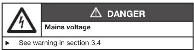
3.4 Mains voltage
| 4 | DANGER |
| Mains voltage | |
| Contact with the mains voltage presents the danger of a deadly electric shock. For that reason, observe the following warnings under all circumstances: • Electrical connections may only be made by a qualified electrician. • The on-site electrical installation must conform to the applicable protective regulations (230/240 V AC, 50/60 Hz)! • Ensure that the national regulations governing the operation of electrical equipment are complied with. • Before undertaking any electrical work, disconnect the system from the mains supply and ensure that it cannot be inadvertently turned on. | |
| ATTENTION |
| External voltage on the connecting terminals External voltage on the connecting terminals of the control will destroy the electronics. ► Do not apply any mains voltage (230/240 V AC) to the connecting terminals of the control. |
To prevent malfunctions:
The connection cables of the operator (24 V DC) must be laid in a separate installation system from the other supply cables (230 V AC).
If laying cables in the ground, use an underground cable (NYY) for all cables (see Figure 3).
If laying cables in the ground as an extension, the connection to the control cables must be in a spray-water protected junction box (IP65, to be provided on site).
All the cables must be inserted into the control unit from below and free from distortion.
Connecting the operators3.5
Operator connection with a single-leaf gate 3.5.1 system
Fit the operator cables to the leaf A plug as shown in Figure 5.2.
Operator connection with a double-leaf gate 3.5.2 system without threshold
See Figure 5.3a
Connect the leaf that opens first or the traffic leaf to the leaf A plug. The operator cable for the other leaf is connected to the leaf B plug. If the leaf sizes vary, the smaller leaf is the traffic leaf or leaf A.
Operator connection with a double-leaf gate 3.5.3 system with threshold
See Figure 5.3b
For gates with a threshold, the first leaf that opens is the traffic leaf or leaf A and is connected to the leaf A plug. The operator cable for the other leaf is connected to the leaf B plug in accordance with Figure 5.3.
4 Initial Start-Up of the Basic Equipment
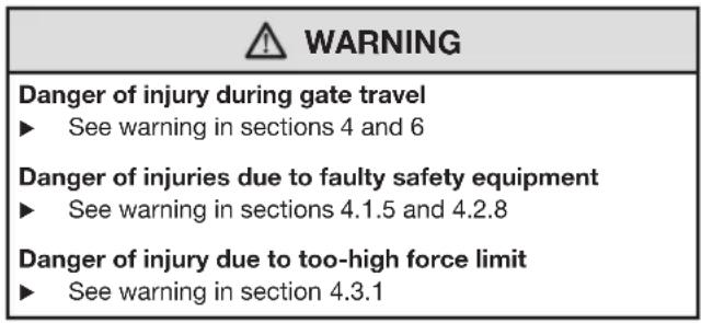
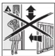
| 警告 WARNING |
| Danger of injury during gate travel If people or objects are in the area around the gate while the gate is in motion, this can lead to injuries or damage. Children are not allowed to play near the gate system. Make sure that no persons or objects are in the gate's travel range. Make sure that no persons or objects are located between the gate and the operator mechanics. If the gate has only one safety feature, only operate the gate operator if you are within sight of the gate's area of travel. Monitor the gate travel until the gate has reached the end-of-travel position. Only drive or pass through remote control gate systems if the gate is in the OPEN end-of-travel position! |
Single-leaf gate system4.1
Fitting the end stop4.1.1
NOTE:
A mechanical end stop is required for the CLOSE end-of-travel position. An electric lock provides the system with additional protection against vandalism and wind loads.
Fitting and connecting the electric lock *4.1.2
See Figure 6
The polarity does not have to be taken into account if connecting electric locks from the accessory list.
Preparations4.1.3
See Figures 7a/7.1a
Uncouple leaf 1. A and open approx. 1m re-couple leaf.
Set all DIL switches to 2. OFF.
Connect the power supply.3.
- DIL switch 1 to ON = single-leaf system
DIL switch 5. 4 to ON = set-up mode
Green LED a. GN flashes = set-up mode
Red LED b. RT is illuminated
Teaching in the 4.1.4 CLOSE end-of-travel position
See Figure 7.2a
- Press and hold circuit board button T. Leaf A moves in the CLOSE direction, comes to a standstill at the end stop, and the motor switches off.
- Release circuit board button T. The gate is now in the CLOSE end-of-travel position. The LED RT remains on after the end-of-travel position has been recorded.
NOTE:
If the gate moves in the OPEN direction, check the motor connection (see Figure 5.2), if necessary, connect the motor correctly, perform a factory reset (see section 6.8) and repeat the steps described in this section.
4.1.5 Teaching in the OPEN end-of-travel position
See Figure 7.2a
- Press and hold circuit board button T and move leaf A into the desired OPEN position. Release circuit board button T.
- If the system overshoots the desired position, press circuit board button T again to move the leaf back a bit. The leaf can also be moved forward a bit by pressing circuit board button T again.
- Once the desired end-of-travel position is reached, briefly press circuit board button P; the OPEN end-of-travel position has now been taught in. The LED GN briefly flashes quickly and then slowly.
DIL switch 4. 4 to OFF
a. The connected safety equipment is activated.
b. Operation via radio is possible
- Use circuit board button T in press-and-release operation to trigger three complete gate cycles to teach in the forces (see section 4.3 and Figure 7.3a).
a. The forces have been taught in if LED GN is illuminated.

WARNING
Danger of injuries due to faulty safety equipment
In the event of a malfunction, there is a danger of injuries due to faulty safety equipment.
After the learning runs, the person commissioning the gate must check the function(s) of the safety equipment as well as the settings (see section 4.4).
The system is ready for operation only after this.
4.2 Double-leaf gate system
4.2.1 Fitting the end stops
Mechanical end stops are required for the CLOSE end-of-travel position (e.g. stop plates *). An electric lock provides the system with additional protection against vandalism and wind loads.
4.2.2 Fitting and connecting electric locks
See Figure 6
The polarity does not have to be taken into account if connecting electric locks from the accessory list.
Preparations4.2.3
See Figures 7b/7.1b
Uncouple leaf 1. A and open approx. 1m re-couple leaf.
- Leaf B must be closed, otherwise uncouple leaf B, move it into the CLOSE position, and re-couple leaf.
Set all DIL switches to 3. OFF.
Connect the power supply.4.
DIL switch 5. 4 to ON = set-up mode
GreenLEDa.GNflashes = set-upmode
Red LED b. RT is illuminated
Teaching in the 4.2.4 CLOSE end-of-travel position for leaf A
See Figure 7.2b
- Press and hold circuit board button T. Leaf A moves in the CLOSE direction, comes to a standstill at the end stop, and the motor switches off.
- Release circuit board button T.
The gate is now in the CLOSE end-of-travel position.
The LED RT remains on after the end-of-travel position has been recorded.
NOTE:
If the gate moves in the OPEN direction, check the motor connection (see Figure 5.3), if necessary, connect the motor correctly, perform a factory reset (see section 6.8) and repeat the steps described in this section.
4.2.5 Teaching in the OPEN end-of-travel position for leaf A
See Figure 7.2b
- Press and hold circuit board button T and move leaf A into the desired OPEN position. Release circuit board button T.
- If the system overshoots the desired position, press circuit board button T again to move the leaf back a bit. The leaf can also be moved forward a bit by pressing circuit board button T again.
- Once the desired end-of-travel position is reached, briefly press circuit board button P; the OPEN end-of-travel position has now been taught in. The LED GN briefly flashes quickly and then slowly.
Teaching in the 4.2.6 CLOSE end-of-travel position for leaf B
See Figures 7.3b/7.4b
Uncouple leaf 1. B and open approx. 1m re-couple leaf.
2. DIL switch 3 to ON = Teach-in double leaf operation for leaf B.
3. Press and hold circuit board button T. Leaf B moves in the CLOSE direction, comes to a standstill at the end stop, and the motor switches off.
Release circuit board button 4. T.
The gate is now in the CLOSE end-of-travel position.
The LED RT remains on after the end-of-travel position has been recorded.
NOTE:
If the gate moves in the OPEN direction, check the motor connection (see Figure 5.3), if necessary, connect the motor correctly, perform a factory reset (see section 6.8) and repeat the steps described in this section.
4.2.7 Teaching in the OPEN end-of-travel position for leaf B
See Figure 7.4b
- Press and hold circuit board button T and move leaf B into the desired OPEN position. Release circuit board button T.
If the system overshoots the desired position, press 2. circuit board button T again to move the leaf back a bit. The leaf can also be moved forward a bit by pressing circuit board button T again.
Once the desired end-of-travel position is reached, briefly 3. press circuit board button P; the OPEN end-of-travel position has now been taught in. The LED GN briefly flashes quickly and then slowly.
Set DIL switch 4.3 to OFF.
Set DIL switch 5.4 to OFF.
The connected safety equipment is activated.a.
Operation via radio is possible.b.
Use circuit board button 6. T in press-and-release operation to trigger three complete gate cycles to teach in the forces (see section 4.3 and Figure 7.5b).
a. The forces have been taught in if LED GN is illuminated.
- If necessary, set the leaf offset function (see section 4.2.8).
4.2.8 With/without leaf offset and size of leaf offset
See Figures 8.1/8.2
In double-leaf gate systems with a threshold, the leaves may collide during travel. This is why the leaf offset must be activated after the teach-in process!
To ensure that the leaves do not collide during travel in a double-leaf gate system, a large leaf offset is expedient in asymmetrical gates with a threshold whereas a small leaf offset suffices for symmetrical gates with a threshold.
Setting the leaf offset function:
- Set the leaf offset function with DIL switch 2.
| 2 ON | Without leaf offset: Leaf A and B open and close simultaneously. |
| 2 OFF | With leaf offset: Leaf A opens before leaf B; leaf B closes before leaf A. |
- Set the size of the leaf offset with DIL switch 3:
| 3 ON | Leaf B/small leaf offset |
| 3 OFF | Leaf A/large leaf offset |

WARNING
Danger of injuries due to faulty safety equipment In the event of a malfunction, there is a danger of injuries due to faulty safety equipment.
After the learning runs, the person commissioning the gate must check the function(s) of the safety equipment as well as the settings (see section 4.6).
The system is ready for operation only after this.
4.3 Force learning runs
Once the end-of-travel positions have been taught in or after specific changes, the forces must be taught in again. The gate must be closed and two uninterrupted gate cycles must take place, throughout which none of the safety devices may be activated. Recording the forces takes place automatically by press-and-release operation in both directions, i.e. once an impulse has been given, the operator causes the gate to travel to the end-of-travel position. The LED GN flashes throughout. This LED is steadily illuminated once the force learning runs have been completed (see Figures 7.3a/7.5b).
Both of the following procedures must be conducted two times.
Teaching in the forces to the OPEN end-of-travel position:
Press circuit board button T once.
The operator automatically moves into the OPEN end-of-travel position.
Teaching in the forces to the CLOSE end-of-travel position:
Press circuit board button T once.
The operator automatically moves into the CLOSE end-of-travel position.
4.3.1 Setting the force limit
Due to special fitting situations, it can, however, happen that the previously taught-in forces are not high enough which can then lead to undesired reversing. In such cases, the force limit can be readjusted with a potentiometer, which is located on the circuit board and labelled with Kraft F.

WARNING
Force limit too high
If the force limit has been set too high, the gate will not stop on time when closing and may trap persons or objects.
Do not set a force limit that is too high.
The increase in the force limit is a percentage increase in relation to the taught-in values; in the process, the setting of the potentiometer denotes the following force increase (see Figure 9):
| Full left | + 0% force |
| Centred | +15% force |
| Full right | +75% force |
To adjust the force limit:
- Adjust the potentiometer Kraft F in the desired direction. The taught-in force setting must be checked using a 2. suitable force measuring device to make sure that the values are permissible within the application scope of the European Standards EN 12453 and EN 12445 or the corresponding national regulations.
If the measured force is too high when the potentiometer 3. setting for the force limit is 0% it can be reduced via a lower travel speed for normal and slow speed (see section 4.6.2).
4.4 Connecting the safety device *
See Figure 10.1b
A 2-wire photocell can be connected to the SE1 safety circuit.
Safety device SE1 in the 4.4.1 CLOSE direction
Safety device SE1 in the CLOSE direction. If triggered, delayed, long reversing up to the OPEN end-of-travel position (see Figure 10.1)
Electrical connection
| Terminal 20 0 V (power supply) |
| Terminal 73 SE1 switch signal input |
Function selection via the DIL switches
| 5 ON 2-wire | photocell |
| 5 OFF | No safety equipment |
NOTE:
Automatic timed closing can only be activated if the safety device has been activated.
Connecting additional components/accessories4.5
NOTE:
Loading of the 24 volt supply for the operator by all accessories: max. 100mA
Connecting a warning lamp *4.5.1
See Figure 10.2a
A warning lamp (e.g. for warnings before and during gate travel) or CLOSE limit switch reporting can be connected to the volt-free contacts on the Option terminal. The voltage to operate the 24V lamp (max. 7 W) can be tapped from the control (terminal 24V =
NOTE:
A 230V warning lamp must have an external supply (see Figure 10.2b).
Connecting external buttons *4.5.2
See Figure 10.3
One or more buttons with normally open contacts (volt-free or switching to 0V ), e.g. key switches, can be connected in parallel, max. cable length 40m (in a cable system separated from the 230V cables).
Single-leaf gate system
Impulse control:
First contact to terminal 21
Second contact to terminal 20
Double-leaf gate system
Impulse control travel command for traffic leaf (A):
First contact to terminal 23
Second contact to terminal 20
Impulse control travel command for traffic leaf (A) and fixed leaf (B):
First contact to terminal 21
Second contact to terminal 20
NOTE:
If auxiliary voltage is needed for external command units, then a voltage of +24V DC is available for this at terminal 5 (against terminal 20 = 0V ).
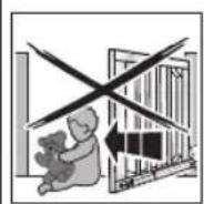
4.5.3 Connecting a cut-out to stop and/or switch off the operator (STOP or emergency-OFF circuit) *
See Figure 10.4
This switch immediately stops gate travel and prevents further gate travel.
A cut-out with normally closed contacts (switching to 0V or volt-free) is connected as follows:
- Remove the wire jumper inserted at the factory between terminal 12 (STOP or emergency-OFF input) and terminal 13 (0 V).
- Connect switching output or first contact at terminal 12 (STOP or emergency-OFF input).
- Connect 0V (ground) or second contact with terminal 13 (0 V).
4.6 Setting additional functions via the DIL switches
The control is programmed via the DIL switches.
Before initial start-up, the DIL switches are in factory settings, i.e. the switches are in the OFF position (see
Figures 7.1a/7.1b). Changes to the DIL switch settings are only permissible under the following conditions:
The operator is at rest.
The warning or hold-open phase is not active.
The LED GN does not flash.
Set the DIL switches as described below in accordance with the national regulations, the desired safety equipment and the on-site conditions.
4.6.1 DIL switch 6/7: automatic timed closing/pre-warning phase/option relay
The functions of the operator (automatic timed closing/5 s pre-warning time) and the function of the option relay are set with DIL switch 6 in combination with DIL switch 7.
NOTE:
Automatic timed closing can only be activated if at least one safety device has been activated.
See Figure 11.1
| 6 OFF | 7 OFF | Operator No special function |
| Option relay Relay picks up in the CLOSE end-of-travel position. |
See Figure 11.2
| 6 ON 7 OFF Operator | Automatic timed closing, pre- warning time only for automatic timed closing |
| Option relay Relay clocks rapidly during the pre- warning time, normally during the travel phase and is OFF during the hold-open phase. |
See Figure 11.3
| 6 OFF 7 ON Operator | Warning phase for every gate travel without automatic timed closing |
| Option relayRelay clocks rapidly during the pre-warning time and normally during the travel phase |
See Figure 11.4
| 6 ON 7 ON | Operator | Automatic timed closing, pre- warning time for each gate movement |
| Option relayRelay clocks rapidly during the pre- warning time, normally during the travel phase and is OFF during the hold-open phase. |
NOTE:
Automatic timed closing is only possible from the OPEN end-of-travel position. If the force limit is activated during closing, the gate briefly reverses in the OPEN direction and stops. If the photocell is activated during closing, the gate reverses into the OPEN end-of-travel position and automatic timed closing is started again.
4.6.2 Slow travel speed
If the measured force is too high when the potentiometer setting for the force limit is 0% , it can be reduced via a lower travel speed.
To reduce the travel speed:
Set DIL switch1. 8 to ON.
| 8 ON Slow travel speed for all runs |
| 8 OFF Normal travel speed for all runs |
Perform three successive force learning runs 2. (see section 4.3).
Check the force again with a force measuring device.3.
5 Radio
5.1 Hand transmitter RSC 2
| 警告 | WARNING |
| Danger of injury during gate travelPersons may be injured by gate travel if the hand transmitter is actuated.Make sure that the handtransmitters are kept away fromchildren and can only be used bypeople who have been instructedon how the remote-control gatefunctions!If the gate has only one safetyfeature, only operate the handtransmitter if you are within sight ofthe gate!Only drive or pass through remotecentral gate systems if the gate is inthe OPEN end-of-travel position!Please note that unwanted gatecycles may occur if a handtransmitter button is accidentallypressed (e.g. if stored in a pocket/handbag). |
| CAUTION |
| Danger of injuries due to unintended gate travel Unintended gate travel may occur while teaching in the radio system. ▶ Pay attention that no persons or objects are in the gate's travel range when teaching in the radio system. |
| ATTENTION |
| Functional disturbances caused by environmental conditions |
| These conditions can impair function! |
| Protect the hand transmitter from the following conditions: |
| Direct sunlight (perm. ambient temperature: -20°C to • +60°C) |
| Moisture• |
| Dust• |
NOTES:
Perform a functional check after programming or extending the remote control system.
- Only use original components for the initial start-up or for extending the remote control system.
- Local conditions may affect the range of the radio system.
The hand transmitter works with a rolling code that changes with each sending procedure. For this reason, it must be taught in with the desired hand transmitter button on each receiver that is to be controlled (see section 5.2.1 or the receiver's operating instructions).
Control elements5.1.1
See Figure 12
1 LED
2 Hand transmitter buttons
3 Battery
Inserting/changing the battery5.1.2
See Figure 12
Only use the battery type CR2025, 3 V Li, and pay attention to the correct polarity.
Hand transmitter LED signals5.1.3
LED illuminated:
The hand transmitter is sending a radio code.
LED flashing:
The hand transmitter is transmitting, but the battery charge is so low that it must be replaced soon.
No LED response:
The hand transmitter is not functioning.
Check whether the battery has been inserted - correctly.
Exchange the battery for a new one.-
Excerpt from the declaration of conformity5.1.4
Conformity of the abovementioned product with the requirements of the directives according to article 3 of the R & TTE directives 1999/5/EC was verified by compliance with the following standards:
EN 300 220-2
EN 301 489-3
EN 50371
EN 60950-1
The original declaration of conformity can be requested from the manufacturer.
5.2 Integral radio module
With an integral radio module, the functions Impulse (OPEN/ STOP/CLOSE/STOP) and traffic leaf can be taught in to a maximum of 12 hand transmitters. If more than 12 hand transmitters are taught in, the functions on the one taught in first are deleted.
For programming the radio module or to delete its data, the following conditions must be fulfilled:
No set-up mode is activated (DIL switch 4 to OFF).
The leaves are not moving.
The pre-warning or hold-open phase is not active.
NOTES:
One of the hand transmitter buttons must be programmed for an integral radio module to actuate the operator via radio.
There must be a distance of at least 1m between the hand transmitter and the operator.
5.2.1 Teaching in the hand transmitter buttons for an integral radio module
Single-leaf operation:
See Figure 12.1
Channel 1 / 2 =
Leaf A
Double-leaf operation:
See Figure 12.2
Channel 1 =
Leaf A+B
Channel 2 =
Leaf A
- Briefly press circuit board button P 1x for channel 1 or 2x for channel 2. Pressing circuit board button P again will immediately end radio programming. Depending on the channel being programmed, the LED RT will flash 1x (for channel 1) or 2x (for channel 2). During this time, a hand transmitter button can be programmed for the desired function.
- Press the hand transmitter button to be taught in until the red LED on the circuit board flashes rapidly.
- Release the hand transmitter button and press it again within 15 seconds until the LED begins flashing very rapidly.
- Release the hand transmitter button. The red LED remains lit and the hand transmitter button is taught in and ready for operation.
5.2.2 Deleting all data in an integral radio module
- Press and hold circuit board button P. The LED RT flashes slowly, signalling the readiness for deletion.
The flashing then becomes more rapid.
Now the data of all the hand transmitters' taught-in radio codes is deleted. - Release circuit board button P.
5.3 External receiver
Instead of an integral radio module, and external radio receiver can be used for the impulse and traffic leaf functions to control the operator.
5.3.1 Connecting an external receiver
- Insert the plug of an external receiver in the corresponding slot (see Figure 12.3). The wires of the external radio receiver should be connected as follows:
GN to terminal 20 (0 V)
- WH to terminal 21 (signal for impulse control channel 1, switching to 0V )
- BN to terminal 5 (+24 V)
- YE to terminal 22 (signal for traffic leaf channel 2, switching to 0 V). Only with a 2-channel receiver.
- Delete the data in an integral radio module to prevent double allocation (see section 5.2.2).
- Teach in the hand transmitter buttons for the Impulse (channel 1) and traffic leaf (channel 2) functions using the operating instructions for the external receiver as a basis.
NOTE:
The aerial wire of the external receiver should not come into contact with metal objects (nails, bracing, etc.). The best orientation to achieve an optimum range must be established by trial and error.
6 Operation
WARNING
Danger of injury during gate travel If people or objects are in the area around the gate while the gate is in motion, this can lead to injuries or damage.
Children are not allowed to play near the gate system.
Make sure that no persons or objects are in the gate's travel range.
Make sure that no persons or objects are located between the gate and the operator mechanics.
If the gate has only one safety feature, only operate the gate operator if you are within sight of the gate's area of travel.
Monitor the gate travel until the gate has reached the end-of-travel position.
Only drive or pass through remote control gate systems if the gate is in the OPEN end-of-travel position!
Function tests
Check the function of the mechanical release monthly.
To check the safety reversal, stop the gate with both hands while it is closing.
The gate system must stop and initiate a safety reversal.
In the event of a failure of the safety reversal, a specialist must be commissioned immediately for the inspection and repair work.
Instructing users6.1
Instruct all persons who use the gate system on the proper and safe use of the hinged gate operator.
Demonstrate and test the mechanical release as well as the safety return.
Normal operation6.2
Press circuit board button T, the external button or activate impulse 1.
The gate moves in impulse sequence mode (OPEN/ STOP/CLOSE/STOP).
If impulse 2 is activated, leaf A (traffic leaf) will open if it was previously closed (see Figures 5.3a/5.3b). If the leaf offset is activated, leaf A can only move if leaf B is in the CLOSE end-of-travel position.
Reversing during an opening run6.3
If the force limit is activated during an opening run, the respective leaf will briefly reverse in the CLOSE direction, i.e. the operator moves the gate in the opposite direction and then stops. With a double-leaf gate, the uninvolved leaf stops.
Reversing during a closing run6.4
If the force limit or photocell is activated during a closing run, the respective leaf will briefly reverse in the OPEN direction and then stop. If the photocell is activated, a long reversal until the OPEN end-of-travel position will take place. During impulse operation, the gate remains at a standstill and the time starts again for automatic timed closing.
Behaviour during a power failure6.5
To be able to open or close the hinged gate during a power failure, it must be disengaged from the operator (see Figure 13.1). If the gate is also secured with an electric lock, the lock must be unlocked with the appropriate key beforehand.
Behaviour following a power failure6.6
Once the power supply has been restored, the gate must be reengaged with the operator (see Figure 13.2)
A necessary reference run in the CLOSE direction is automatically performed on the next command impulse following a power failure. During this reference run the option relay clocks and a connected warning lamp flashes slowly.
Disengaging without a power failure6.7
After reengaging the gate, the voltage supply must be disconnected once so that a new reference run is automatically performed in the CLOSE direction.
6.8 Factory reset
This can be used to reset the taught-in end-of-travel positions and forces.
To perform a factory reset:
Set DIL switch 1. 4 to ON.
| 4 ON Set-up | mode |
| 4 OFF | Normal mode in press-and-release operation |
- Immediately press circuit board button P briefly.
- When the LED RT flashes rapidly, quickly set DIL switch 4 to OFF.
- The control has now been reset to the factory settings. The LED GN will flash slowly.
6.9 Operation, error and warning messages
6.9.1 LED GN
The green LED GN (see Figure 5.1) indicates the operating conditions of the control:
| Steady illumination Normal state, all OPEN end-of-travel positions and forces taught in. |
| Fast flashing Force learning runs must be performed. |
| Slow flashing End-of-travel positions must be taught in. |
LED RT6.9.2
The red LED RT (Figure 5.1) indicates:
| Radio programming display Flashing as described in section 5 |
| Display of the button inputs: Actuated = LED is on* Not actuated = LED is off* |
Error/diagnosis display
The LED RT helps to easily identify causes when operation does not go according to plan.
| LED RT Flashes | 2x |
| Error/warning SE | safety/protective device has responded |
| Possible cause | $afety/protective device has been • actuated Safety/protective device defective • |
| Remedy Check | safety/protective device |
| LED RT Flashes | 3x |
| Error/Warning Force limit in CLOSE direction | |
| Possible cause | Obstruction in gate area |
| Remedy Remove | obstruction, check forces, and increase, if necessary |
| LED RT Flashes | 4x |
| Error/Warning Hold or static current circuit is open, operator at a standstill | |
| Possible cause | Normally closed contact at terminal • 12/13 is open Electric circuit interrupted • |
| Remedy Close contact | • Check electric circuit |
| LED RT Flashes | 5x |
| Error/warning Force limit in OPEN direction | |
| Possible cause | Obstruction in gate area |
| Remedy Remove | obstruction, check forces, and increase, if necessary |
| LED RT Flashes | 6x |
| Error/warning System error | |
| Possible cause | Internal error |
| Remedy Restore | the factory setting (see section 6.8) and teach in the control again or exchange, if necessary |
6.10 Error acknowledgement
Acknowledge the error after the cause of the error has been eliminated:
Press the internal or external button or actuate the radio hand transmitter.
The error is deleted and the gate travels in the corresponding direction.
7 Inspection and Maintenance
The gate operator is maintenance-free.
In the interest of your own safety, we recommend having the gate system inspected and maintained by a qualified person in accordance with the manufacturer's specifications.

WARNING
Danger of injury due to unexpected gate travel
Unexpected gate travel can result during inspection and maintenance work if the gate system is inadvertently actuated by other persons.
- Disconnect the mains plug when performing all work on the gate system.
- Safeguard the gate system against being switched on again without authorisation.
An inspection or necessary repairs may only be carried out by a qualified person. Contact your supplier for this purpose.
A visual inspection may be carried out by the operator.
Check all safety and protective functions monthly.
Malfunctions and/or defects at hand must be rectified immediately.
We would like to point out that any repairs not carried out properly or with due professionalism shall render the warranty null and void.
8 Optional Accessories
Optional accessories are not included in the scope of delivery. Loading of the operator by all electrical accessories: max. 100mA
The following accessories are available:
External radio receivers
External impulse buttons (e.g. key switch)
Photocell
- Warning lamps/warning lights
Electric lock for post locking
Electric lock for floor locking
- Stop plate
Set of base plates
9 Dismantling and Disposal
NOTE:
When disassembling, observe the applicable regulations regarding occupational safety.
Have a specialist dismantle the gate operator in the reverse order of these instructions and dispose of it properly.
10 Warranty Conditions
Warranty
We shall be exempt from our warranty obligations and product liability in the event that the customer carries out his own structural alterations or undertakes improper installation work or arranges for same to be carried out by others without our prior approval and contrary to the fitting guidelines we have provided. Furthermore, we will assume no responsibility for the accidental or careless operation of the operator, improper maintenance of the gate and its accessories, or for a non-authorised method of fitting the gate. Batteries, light bulbs and fuses are also not covered by the warranty.
Warranty period
In addition to the statutory warranty from the dealer in the purchase contract, we provide a warranty for a term of 2 years from the purchase date. There is no warranty on consumables (e.g. fuses, batteries, lamps). Claims made under the warranty do not extend the warranty period. For replacement parts and repairs the warranty period is six months or at least the remainder of the warranty period.
Prerequisites
A claim under this warranty is only valid for the country in which the equipment was bought. The product must have been purchased through our authorised distribution channels. A claim under this warranty exists only for damage to the object of the contract itself. Reimbursement of expenditure for dismantling and fitting, testing of corresponding parts, as well as demands for lost profits and compensation for damages, are excluded from the warranty.
The receipt of purchase substantiates your right to claim under the warranty.
Performance
For the duration of the warranty we shall eliminate any product defects that are proven to be attributable to a material or manufacturing fault. We pledge to replace free of charge and at our discretion the defective goods with non-defective goods, to carry out repairs, or to grant a price reduction.
Damages caused by the following are excluded:
improper fitting and connection
improper initial start-up and operation
external factors such as fire, water, abnormal
environmental conditions
mechanical damage caused by accidents, falls, impacts
negligent or intentional destruction
normal wear or deficient maintenance
repairs conducted by unqualified persons
use of non-original parts
removal or defacing of the product number
Replaced parts become the property of the manufacturer.
Excerpt from the Declaration of 11 Incorporation
(as defined in EC Machinery Directive 2006/42/EC for incorporation of partly completed machinery according to annex II, part B)
The product described on the rear side has been developed, constructed and produced in accordance with the:
EC Machinery Directive 2006/42 EC
EC Construction Products Directive 89/106/EEC
EC Low-Voltage Directive 2006/95/EC
EC Electromagnetic Compatibility Directive 2004/108/EC
Applied and consulted standards and specifications:
Safety of machinery - Safety-related parts of control systems - Part 1: General principles
EN 60335-1/2, when applicable
Safety of electrical appliances/Operators for doors
EN61000-6-3
Electromagnetic compatibility - Electromagnetic radiation
EN61000-6-2
Electromagnetic compatibility - Interference immunity
Partly completed machinery as defined in the EC Directive 2006/42/EC is only intended to be incorporated into or assembled with other machinery or other partly completed machinery or equipment, thereby forming machinery to which this directive applies.
This is why this product must only be put into operation after it has been determined that the entire machine/system in which it will be installed corresponds with the guidelines of the EC Directive mentioned above.
12 Technical Data
| Max. gate leaf width | 2,500 mm |
| Max. gate height | 2,000 mm |
| Max. gate weight | 200 kg |
| Max. gate leaf infill | Dependent on the gate surface. Regional wind loads must be taken into account if using gate infills (EN 13241-1). |
| Rated load | See data label |
| Max. pull and push force | See data label |
| Max. spindle speed | Approx. 16 mm/s |
| Gate locking | Electric lock for post and floor locking, recommended: • From a leaf width ≥ 1.500 mm • With partial infill • With increased wind load |
| Operator release | On operator, with eye bolt |
| Operator housing | Plastic |
| Mains voltage | Rated voltage 230 V/50 Hz, power input approx. 0.15 kW |
| Stand-by power input | Approx. 12 W (without additional accessories connected) |
| Control | Microprocessor control system, programmable via 8 DIL switches, control voltage 24 V DC, protection category IP 65 |
| Max. control/operator cable length | 40 m |
| Operating mode | S2, short-time duty 4 minutes |
| Temperature range | -20°C to +60°C |
| Travel/force limit | Electronic |
| Automatic safety cut-out | Force limit for both operational directions, self-programming and testing |
| Hold-open phase for automatic timed closing | 60 seconds (photocell required) |
| Motor | Spindle unit with 24 V DC motor and worm gear, protection category IP 44 |
| Radio remote control | 2-channel receiver, hand transmitter |
Overview of DIL Switch Functions13
| DIL 1 Single or double-leaf operation | |
| ON Single-leaf operation | |
| OFF Double-leaf operation | |
| DIL 2 With/without leaf offset (only with double-leaf operation) | |
| ON Without leaf offset: leaf A and B open and close simultaneously | |
| OFF With leaf offset: leaf A opens before leaf B and leaf B closes before leaf A | |
| DIL 3 Leaf selection/size of leaf offset | |
| ON Leaf B/small leaf offset | |
| OFF Leaf A/large leaf offset | |
| DIL 4 Normal operation/setup operation | |
| ON Set-up mode | |
| OFF Normal mode in press-and-release operation | |
| DIL 5 Safety device SE1 in the CLOSE direction (connection at terminal 73) | |
| ON 2-wire photocell | |
| OFF No safety equipment | # |
| DIL 6 DIL 7 Operator function Option relay function | |||
| ON ON Automatic timing closed closing, pre-warning time for each leaf movement | Relay clocks rapidly during the pre-warning time, normally during the travel phase and is OFF during the hold-open phase | ||
| OFF ON No automatic timed closing, pre-warning time for each leaf movement | Relay clocks rapidly during the pre-warning time, normally during the travel phase | ||
| ON OFF Automatic timed closing, pre-warning time only for automatic timed closing | Relay clocks rapidly during the pre-warning time, normally during the travel phase and is OFF during the hold-open phase | ||
| OFF OFF No special function Relay picks up in the CLOSE end-of-travel position | |||
| DIL 8 Normal/slow travel speed for all runs | |
| ON Slow travel speed for all runs | |
| OFF Normal travel speed for all runs | |
Canal 1/2 = Vantail A
A Anything to be done is the name of the person who has been involved in the incident.
NOTA:
- A Anything to be done is to be done in the way of the commander, or the commander's name, and not by a word of his own.