
Tour Series TNT Combo - Bass amplifier PEAVEY - Free user manual and instructions
Find the device manual for free Tour Series TNT Combo PEAVEY in PDF.
| Brand | Peavey |
| Model | Tour Series TNT Combo |
| Product Type | Bass combo amplifier |
| Category | Bass amp |
| Power supply | 100-240 V AC, 50/60 Hz (universal) |
| Typical power consumption | 100 W |
| Amplifier class | Class D |
| Internal speaker | 15 inches (custom design) |
| Tweeter | Built-in tweeter with on/off switch |
| Equalizer | 7-band graphic, constant Q (+/-15 dB) with bypass |
| Tone controls | Low (50 Hz, +/-15 dB), High (8 kHz, +/-15 dB), Contour, Bright (10 dB at 1 kHz) |
| Compressor | Built-in optical with adjustment and On/Off switch |
| Crunch effect | Built-in (simulates pushed tube amp) with switch |
| DDT™ | Distortion Detection Technique (speaker protection and anti-clip) with bypass switch |
| DI output | Balanced XLR, pre-EQ, with safety circuit (works even when powered off) |
| Effects loop | Buffered (send/return) |
| Headphone output | 1/4" stereo jack |
| External speaker output | Speakon®/1/4" combo jack |
| Instrument input | 1/4" jack with active/passive switch |
| Optional pedal | 1/4" jack for TNT footswitch (controls Crunch and compressor) |
| Ground lift | Switch for ground loop |
| Logo backlight | On/off switch for Peavey logo |
| Weight | 33.3 kg (73.4 lb) |
| Dimensions (W x H x D) | 55.9 x 59.2 x 49.5 cm (22.0" x 23.3" x 19.5") |
Frequently Asked Questions - Tour Series TNT Combo PEAVEY
User questions about Tour Series TNT Combo PEAVEY
0 question about this device. Answer the ones you know or ask your own.
Ask a new question about this device
Download the instructions for your Bass amplifier in PDF format for free! Find your manual Tour Series TNT Combo - PEAVEY and take your electronic device back in hand. On this page are published all the documents necessary for the use of your device. Tour Series TNT Combo by PEAVEY.
USER MANUAL Tour Series TNT Combo PEAVEY
Tour™ Series TNT Combo Tour™ Series TKO Combo
Bass Amplifiers
Operating Manual


Intended to alert the user to the presence of uninsulated "dangerous voltage" within the product's enclosure that may be of sufficient magnitude to constitute a risk of electric shock to persons.
Intended to alert the user of the presence of important operating and maintenance (servicing) instructions in the literature accompanying the product.
CAUTION: Risk of electrical shock — DO NOT OPEN!
CAUTION: To reduce the risk of electric shock, do not remove cover. No user serviceable parts inside. Refer servicing to qualified service personnel.
WARNING: To prevent electrical shock or fire hazard, this apparatus should not be exposed to rain or moisture, and objects filled with liquids, such as vases, should not be placed on this apparatus. Before using this apparatus, read the operating guide for further warnings.
Protective earthing terminal. The apparatus should be connected to a mains socket outlet with a protective earthing connection.

aal aaii jaae iie 100000000000000000000000000000000000000000000000
aill 1000
12 2


J 1
IMPORTANT SAFETY INSTRUCTIONS
WARNING: When using electrical products, basic cautions should always be followed, including the following:
- Read these instructions.
- Keep these instructions.
- Heed all warnings.
- Follow all instructions.
- Do not use this apparatus near water.
- Clean only with a dry cloth.
- Do not block any of the ventilation openings. Install in accordance with manufacturer's instructions.
- Do not install near any heat sources such as radiators, heat registers, stoves or other apparatus (including amplifiers) that produce heat.
- Do not defeat the safety purpose of the polarized or grounding-type plug. A polarized plug has two blades with one wider than the other. A grounding type plug has two blades and a third grounding plug. The wide blade or third prong is provided for your safety. If the provided plug does not fit into your outlet, consult an electrician for replacement of the obsolete outlet.
- Protect the power cord from being walked on or pinched, particularly at plugs, convenience receptacles, and the point they exit from the apparatus.
- Only use attachments/accessories provided by the manufacturer.
- Use only with a cart, stand, tripod, bracket, or table specified by the manufacturer, or sold with the apparatus. When a cart is used, use caution when moving the cart/apparatus combination to avoid injury from tip-over.
- Unplug this apparatus during lightning storms or when unused for long periods of time.
Refer all servicing to qualified service personnel. Servicing is required when the apparatus has been damaged in any way, such as power-supply cord or plug is damaged, liquid has been spilled or objects have fallen into the apparatus, the apparatus has been exposed to rain or moisture, does not operate normally, or has been dropped. - Never break off the ground pin. Write for our free booklet "Shock Hazard and Grounding." Connect only to a power supply of the type marked on the unit adjacent to the power supply cord.
- If this product is to be mounted in an equipment rack, rear support should be provided.
- Note for UK only: If the colors of the wires in the mains lead of this unit do not correspond with the terminals in your plug, proceed as follows: a) The wire that is colored green and yellow must be connected to the terminal that is marked by the letter E, the earth symbol, colored green or colored green and yellow. b) The wire that is colored blue must be connected to the terminal that is marked with the letter N or the color black. c) The wire that is colored brown must be connected to the terminal that is marked with the letter L or the color red.
- This electrical apparatus should not be exposed to dripping or splashing and care should be taken not to place objects containing liquids, such as vases, upon the apparatus.
- The on/off switch in this unit does not break both sides of the primary mains. Hazardous energy can be present inside the chassis when the on/off switch is in the off position. The mains plug or appliance coupler is used as the disconnect device, the disconnect device shall remain readily operable.
- Exposure to extremely high noise levels may cause a permanent hearing loss. Individuals vary considerably in susceptibility to noise-induced hearing loss, but nearly everyone will lose some hearing if exposed to sufficiently intense noise for a sufficient time. The U.S. Government's Occupational Safety and Health Administration (OSHA) has specified the following permissible noise level exposures:
| Duration Per Day In Hours Sound Level dBA, Slow Response | ||
| 8 90 | ||
| 6 92 | ||
| 4 95 | ||
| 3 97 | ||
| 2 100 | ||
| 1 1/2 102 | ||
| 1 105 | ||
| 1/2 | 110 | |
| 14 or less | 115 | |
According to OSHA, any exposure in excess of the above permissible limits could result in some hearing loss. Earplugs or protectors to the ear canals or over the ears must be worn when operating this amplification system in order to prevent a permanent hearing loss, if exposure is in excess of the limits as set forth above. To ensure against potentially dangerous exposure to high sound pressure levels, it is recommended that all persons exposed to equipment capable of producing high sound pressure levels such as this amplification system be protected by hearing protectors while this unit is in operation.
a) The wire that is colored green and yellow must be connected to the terminal that is marked by the letter E, the earth symbol, colored green or colored green and yellow.
b) The wire that is colored blue must be connected to the terminal that is marked with the letter N or the color black.
c) The wire that is colored brown must be connected to the terminal that is marked with the letter L or the color red.
- 2.已自到国
- 4.告
- 期元用国
- 期子用中,自志之和,于国,,,,,,,,,,,,,,,,,,,,,,,,,,,,,,,,,,,,,,,,,,,,,,
- 电
- 这首诗是《喜马拉雅湖》中最写意的歌之一,它写的是“我”和“你”的关系。
- Note for UK only: If the colors of the wires in the mains lead of this unit do not correspond with the terminals in your plug, proceed as follows: a) The wire that is colored green and yellow must be connected to the terminal that is marked by the letter E, the earth symbol, colored green or colored green and yellow. b) The wire that is colored blue must be connected to the terminal that is marked with the letter N or the color black. c) The wire that is colored brown must be connected to the terminal that is marked with the letter L or the color red.
- 1
- 1
a a a a a a a a a a a a a a a a a a a a a a a a a a a
Logo referenced in Directive 2002/96/EC Annex O.U.(L)37/38,13.023 and defined in EN 50419-2:
The bar is the symbol for marking of new waste and is applied only to equipment manufactured after 13 August 2005
Correct Disposal of this product. This marking indicates that this product should not be disposed with other house hold wastes throughout the EU. To prevent possible harm to the environment or human health from uncontrolled waste disposal, recycle it responsibly to promote the sustainable reuse of material resources. To return your used device, please use the return and collection systems, or contact the retailer where the product was purchased. They can take this product for environmental safe recycling.

This device complies with Part 15 of the FCC rules.
Operation is subject to the following two conditions:
(1) this device may not cause harmful interference, and
(2) this device must accept any interference received, that may cause undesired operation.
Changes or modifications to the equipment not approved by Peavey Electronics Corp. can void the user's authority to use the equipment.
Note - This equipment has been tested and found to comply with the limits for a Class B digital device, pursuant to Part 15 of the FCC Rules. These limits are designed to provide reasonable protection against harmful interference in a residential installation. This equipment generates, uses and can radiate radio frequency energy and, if not installed and used in accordance with the instructions, may cause harmful interference to radio communications. However, there is no guarantee that interference will not occur in a particular installation. If this equipment does cause harmful interference to radio or television reception, which can be determined by turning the equipment off and on, the user is encouraged to try and correct the interference by one or more of the following measures.
- Reorient or relocate the receiving antenna.
- Increase the separation between the equipment and receiver.
- Connect the equipment into an outlet on a circuit different from that to which the receiver is connected.
- Consult the dealer or an experienced radio/TV technician for help.
ENGLISH
Tour™ Series TNT® & TKO® Combos
Bass Amplifiers
Welcome to Peavey® bass amplification!
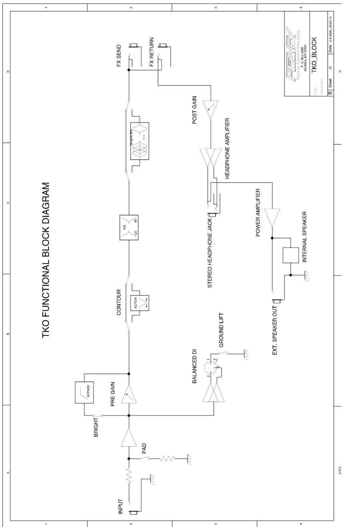
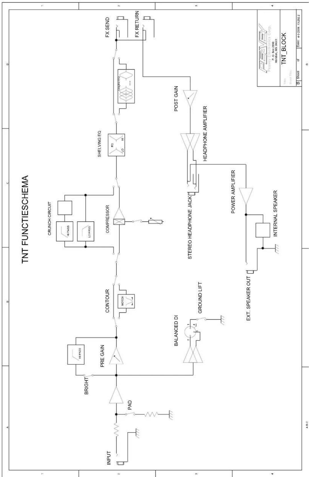
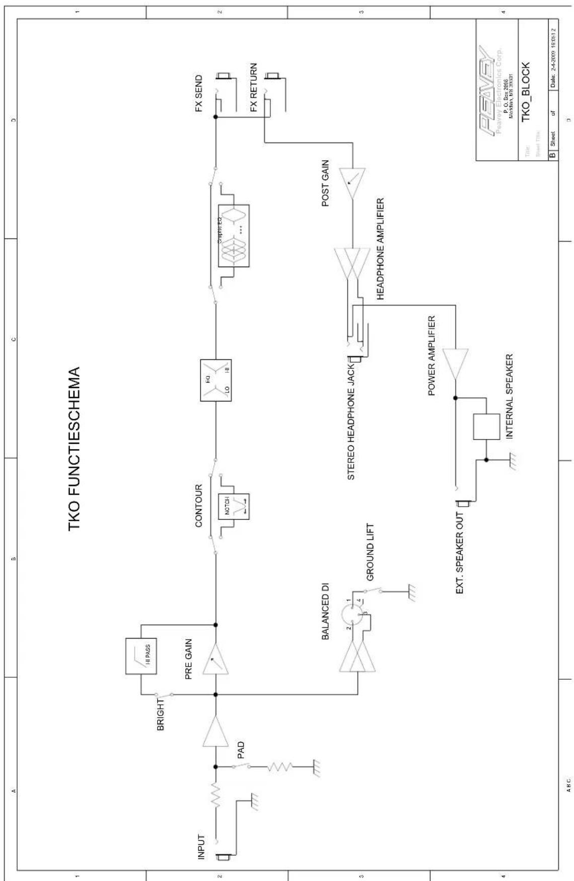
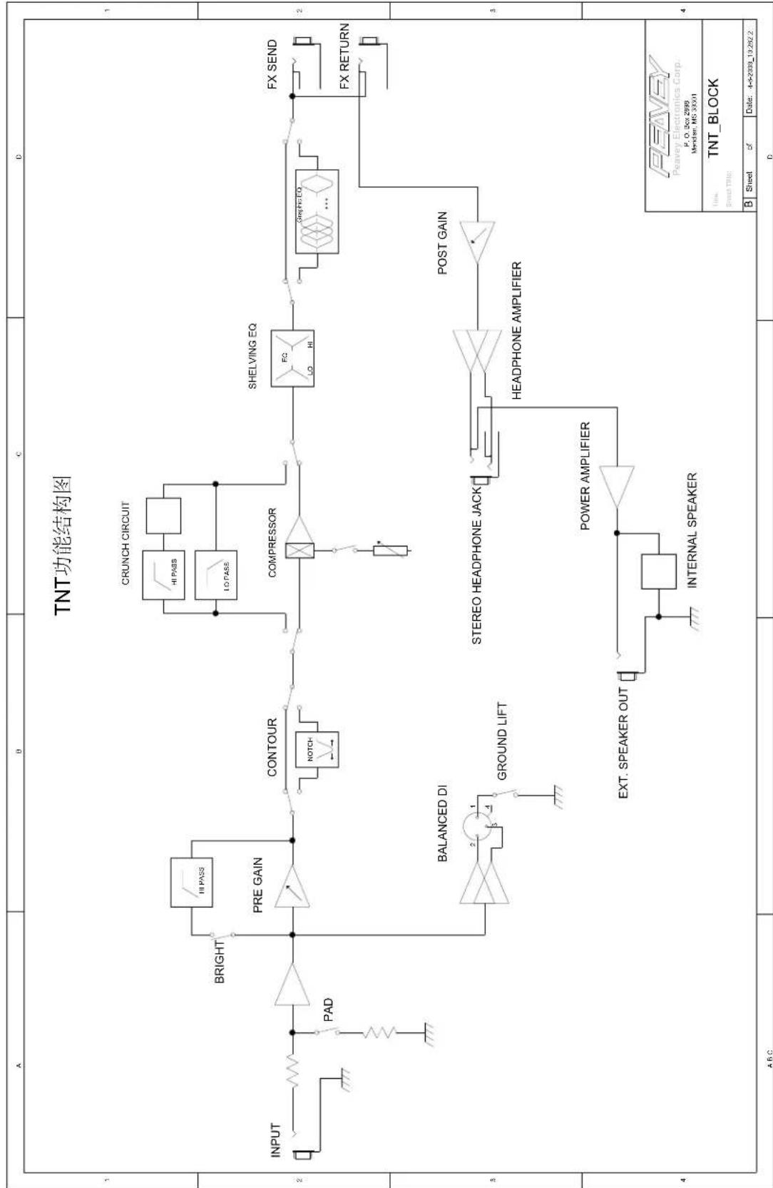
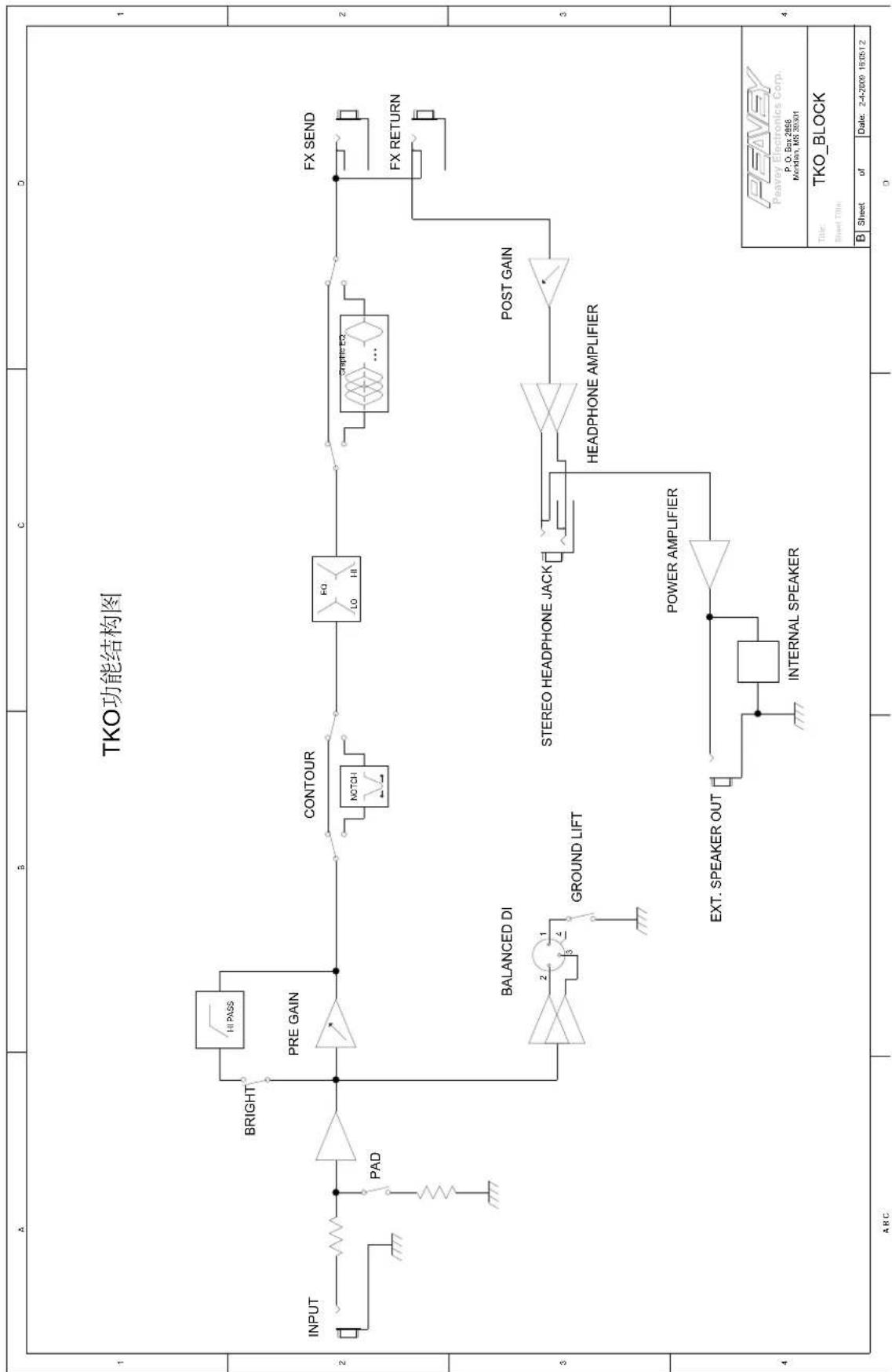
Peavey bass guitar amplifiers are legendary for their state of the art features, class-leading power, superb tone, and unmatched reliability. Your new Tour series TKO or TNT is no exception. Peavey's award-winning Tour series amplifiers provide the backbone for countless touring acts worldwide. Peavey TKO and TNT combos have set the standard for bass combo performance over three decades. Your Tour series edition features a class D power amp, custom-designed 15" bass driver, built-in tweeter, and a tilt-back cabinet design that will push your tone to the back of the house, while still delivering great low-volume practice and studio performance. Your amp is not only versatile with its powerful EQ and tone controls, it's expandable with the extension speaker output on the back, should the need for higher volume levels arise. If you are a TNT owner, you will love the built-in optical compressor and vintage crunch effect. TKO users will love the easy to use controls and modern cabinet styling.
Please read this guide carefully to ensure your personal safety as well as the safety of your amplifier.
FEATURES:
- Bypassable 7-band graphic equalizer with push-button bypass
Class D Power Section - Patented DDT™ (Distortion Detection Technique) technology
Built-In Crunch effect (TNT) - Tweeter On/Off switch (TNT)
- Studio quality balanced DI output
Built-in Optical compressor (TNT) - Buffered Effects Loop
- Speakon® combination Powered Speaker Output (1/4" on TKO)
Active/Passive Instrument Switch
Pre and Post Gain controls
Low & High Shelving EQ - Contour Control

VENTILATION: For proper ventilation, allow 12" clearance from the nearest combustible surface.
All vents should have a minimum of 2" of free air space so air can flow thru the unit freely for proper cooling.

WARNING: Changes or modifications to this unit not expressly approved by the party responsible for compliance could void the user's authority to operate the equipment.
NOTE: This equipment has been tested and found to comply with the limits for a Class B digital device, pursuant to Part 15 of the FCC Rules. These limits are designed to provide reasonable protection against harmful interference in a residential installation. This equipment generates, uses and can radiate radio frequency energy and if not installed and used in accordance with the instructions, may cause harmful interference to radio communications.
However, there is no guarantee that interference will not occur in a particular installation. If this equipment does cause harmful interference to radio or television reception, which can be determined by turning the equipment off and on, the user is encouraged to try to correct the interference by one or more of the following measures:
- Reorient or relocate the receiving antenna.
- Increase the separation between the equipment and receiver.
- Connect the equipment into an outlet on a circuit different from that to which the receiver is connected.
- Consult the dealer or an experienced radio/TV technician for help.
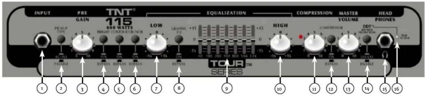

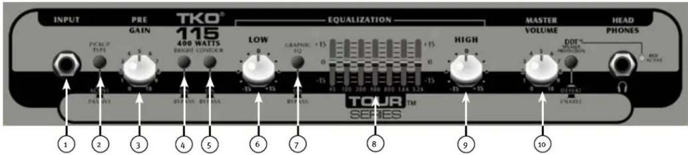
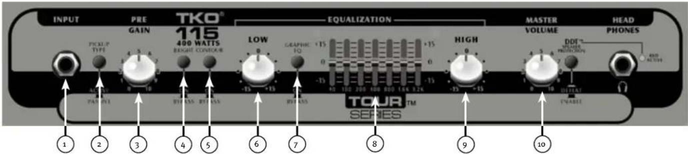
INPUT
1/4" Instrument Input
WARNING: Never plug the output of a power amplifier into the input jacks. Damage may occur to both units.

ACTIVE/PASSIVE PICKUP SWITCH
This switch is included so you can choose the appropriate setting for your instrument. Passive pickups have a lower output, so the gain structure of the amplifier is modified to accommodate the different pickup configurations.

PRE GAIN
This knob the controls input level of the instrument.

BRIGHT SWITCH
This button provides a 10 dB boost to frequencies above 1KHz. To activate, depress the switch to its "IN" position.

CONTOUR
This button boosts highs and lows while simultaneously cutting mid tones, producing a "scooped" sound.

CRUNCH SWITCH
This button engages a crunch effect, simulating the classic overdriven tube amp sound.

LOW
This knob provides a shelving tone control for low frequencies and provides cut/boost of +/-15 dB. The center point is flat. The center frequency is 50 Hz -3 dB; the shelf corner frequency is 100 Hz.

EQ BYPASS
This button removes the graphic equalizer from the audio chain. The "OUT" position of the switch bypasses the EQ, and the amp will respond as if the graphic equalizer is set flat.

GRAPHIC EQUALIZER
These sliders provide precise tone control through the constant-Q, seven band equalizer. Each band may be boosted or cut 15 dB.

HIGH
This knob provides a shelving tone control for high frequencies and cut/boost of +/-15dB . The center point is flat and the frequency is 8 KHz -3 dB; the shelf corner frequency is 5 KHz.

COMPRESSOR
Rotating this knob clockwise will increase the amount of compression in the signal chain.
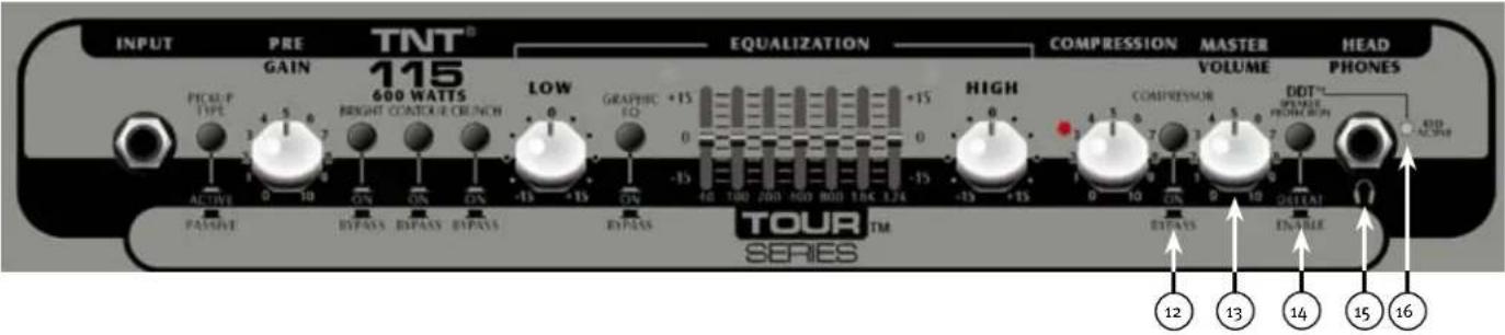
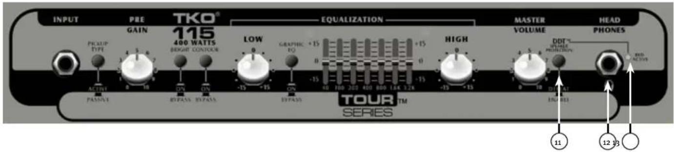
12 COMPRESSOR ON/OFF SWITCH
This button turns the compressor on or off.
VOLUME
This knob controls the overall volume of the amplifier.
This button prevents power amplifier clipping that can sound bad and damage speakers. The "IN" or "DEFEAT" position of the switch bypasses the DDT circuit. However, Peavey recommends the DDT stay enabled for optimum system performance.
15 HEADPHONE OUTPUT
1/4" headphone output for personal monitoring.
DDT INDICATOR LIGHT
When the DDT is enabled, the red Protect/ClipLED will flash when DDT is triggered. It is normal operation for the LED to flash. However, if the LED is constantly illuminated, the gain level needs to be adjusted to prevent possible equipment damage. When the DDT is defeated, the LED becomes a clip indicator.
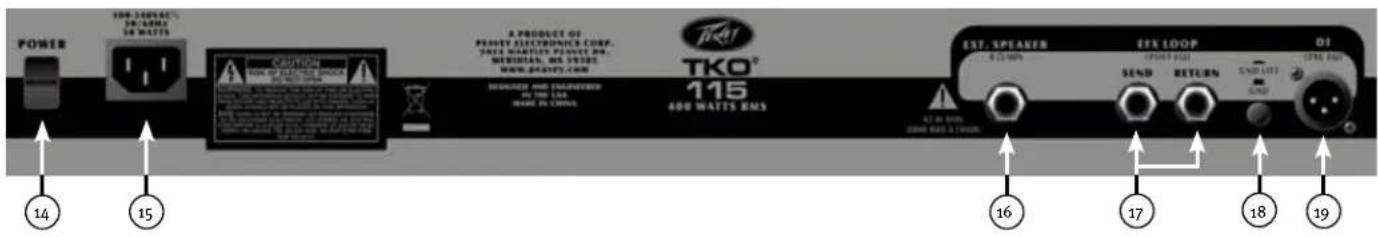
(17) POWER SWITCH
To apply power to the unit, flip the switch to the "On" position. The green LED will illuminate, indicating power is being supplied.

CAUTION: The on/off switch in this unit does not break both sides of the primary mains. Hazardous can be present inside the chassis even when the on/off switch is in the OFF position.
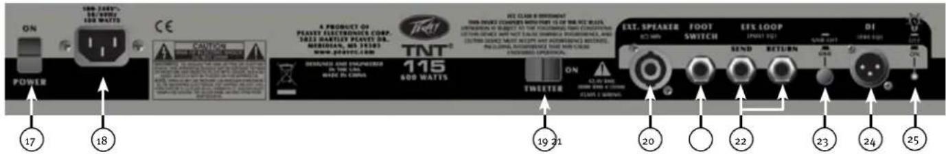


AC POWER INLET:
This is the receptacle for an IEC line cord, which provides AC power to the unit. Connect the line cord to this connector to provide power to the unit. Damage to the equipment may result if improper line voltage is used. (See line voltage marking on unit).
Never break off the ground pin on any equipment. It is provided for your safety. If the outlet used does not have a ground pin, a suitable grounding adapter should be used, and the third wire should be grounded properly. To prevent the risk of shock or fire hazard, always make sure that the amplifier and all associated equipment is properly grounded.
NOTE: FOR UK ONLY
As the colors of the wires in the mains lead of this apparatus may not correspond with the colored markings identifying the terminals in your plug, proceed as follows: (1) The wire that is colored green and yellow must be connected to the terminal that is marked by the letter E, or by the Earth symbol, or colored green or green and yellow. (2) The wire that is colored blue must be connected to the terminal that is marked with the letter N, or the color black. (3) The wire that is colored brown must be connected to the terminal that is marked with the letter L, or the color red.
TWEETER SWITCH
This switch turns the tweeter on/off. Usually when the CRUNCH effect is engaged, this switch would be switched to the OFF position.
EXTERNAL SPEAKER OUTPUT
"Combi" type powered output for powering a passive enclosure.
FOOTSWITCH JACK
Plug your TNT footswitch into this 1 / 4 '' jack. The footswitch controls the crunch effect and the compressor on/off.
NOTE: The crunch and compressor buttons MUST be pushed in to operate with the footswitch.
EFFECTS LOOP
The Send Jack provides a pre amp output that may be used to drive slave amplifiers and external effects processors. The Return Jack provides a power amp input for the last effect in the chain.
NOTE: When using the unit as a slave power amplifier, the Return Jack should be used as the input.
GROUND LIFT
This button is provided to prevent a ground loop that may result in "hum" noise. When depressed (IN position), Ground Lift is engaged.
DIRECT INTERFACE (DI)
This is a built-in, balanced Direct Interface used to send a buffered, unprocessed signal to an external mixer.
PEAVEY LOGO BACKLIGHT SWITCH
This button turns the backlight on the Peavey Logo on or off.

INPUT
1/4" Instrument Input
WARNING: Never plug the output of a power amplifier into the input jacks. Damage may occur to both units.
ACTIVE/PASSIVE PICKUP SWITCH
This switch is included so you can choose the appropriate setting for your instrument. Passive pickups have a lower output, so the gain structure of the amplifier is modified to accommodate the different pickup configurations.
PRE GAIN
This knob controls the input level of the instrument.
BRIGHT SWITCH
This button provides a 10 dB boost to frequencies above 1KHz. To activate, depress the switch to its "IN" position.
CONTOUR
This button boosts highs and lows while simultaneously cutting mid tones, producing a "scooped" sound.
LOW
This knob provides a shelving tone control for low frequencies and provides cut/boost of +/-15 dB. The center point is flat. The center frequency is 50 Hz -3 dB; the shelf corner frequency is 100Hz.
EQ BYPASS
This button removes the graphic equalizer from the audio chain. The "IN" position of the switch bypasses the EQ, and the amp will respond as if the graphic equalizer is set flat.
GRAPHIC EQUALIZER
These sliders provide precise tone control through the constant-Q, nine band equalizer. Each band may be boosted or cut 15 dB.
HIGH
This knob provides a shelving tone control for high frequencies and cut/boost of +/-15dB . The center point is flat and the frequency is 8 KHz -3 dB; the shelf corner frequency is 5 KHz.
MASTER VOLUME
This knob controls the overall volume of the amplifier.
11 DDT™ (Distortion Detection Technique)
This button prevents power amplifier clipping that can sound bad and damage speakers. The "IN" or "DEFEAT" position of the switch bypasses the DDT circuit. However, Peavey recommends the DDT stay enabled for optimum system performance.
HEADPHONE OUTPUT
1 / 4 "headphone output for personal monitoring.
DDT INDICATOR LIGHT
When the DDT is enabled, the red Protect/Clip LED will flash when DDT is triggered. It is normal operation for the LED to flash. However, if the LED is constantly illuminated, the gain level needs to be adjusted to prevent possible equipment damage. When the DDT is defeated, the LED becomes a clip indicator.
POWER SWITCH
To apply power to the unit, flip the switch to the "On" position. The green LED will illuminate, indicating power is being supplied.

CAUTION: The on/off switch in this unit does not break both sides of the primary mains.
ous energy can be present inside the chassis even when the on/off switch is in the
Off position.
AC POWER INLET:
This is the receptacle for an IEC line cord, which provides AC power to the unit. Connect the line cord to this connector to provide power to the unit. Damage to the equipment may result if improper line voltage is used. (See line voltage marking on unit).
Never break off the ground pin on any equipment. It is provided for your safety. If the outlet used does not have a ground pin, a suitable grounding adapter should be used, and the third wire should be grounded properly. To prevent the risk of shock or fire hazard, always make sure that the amplifier and all associated equipment is properly grounded.
NOTE: FOR UK ONLY
As the colors of the wires in the mains lead of this apparatus may not correspond with the colored markings identifying the terminals in your plug, proceed as follows: (1) The wire that is colored green and yellow must be connected to the terminal that is marked by the letter E, or by the Earth symbol, or colored green or green and yellow. (2) The wire that is colored blue must be connected to the terminal that is marked with the letter N, or the color black. (3) The wire that is colored brown must be connected to the terminal that is marked with the letter L, or the color red.
EXTERNAL SPEAKER OUTPUT
1/4" powered output for powering a passive enclosure.
EFFECTS LOOP
The Send Jack provides a pre amp output that may be used to drive slave amplifiers and external effects processors. The Return Jack provides a power amp input for the last effect in the chain.
NOTE: When using the unit as a slave power amplifier, the Return Jack should be used as the input.
GROUND LIFT
This button is provided to prevent a ground loop that may result in "hum" noise. When depressed (IN position), Ground Lift is engaged.
DIRECT INTERFACE (DI)
This is a built-in, balanced Direct Interface used to send a buffered, unprocessed signal to an external mixer.
NOTE: The Direct Interface features failsafe circuitry, which runs on standard 48-volt phantom power from the mixer. This allows the DI to continue functioning even in the event of a blown circuit breaker or amplifier shutdown. In the event of a failsafe operation, the mute switch will be bypassed. This circuit is active, even when the power switch is in the "Off" position.
Tour™ Series Specifications
Tour Series TNT® Combo
NOTE: All specifications tested with mains voltage maintained at nominal level.
Line Voltage:
100 VAC to 240 VAC 50/60 Hz universal power supply
CAUTION: Do not switch line voltage while unit is powered on. Doing so may cause damage to unit.
Typical Power Consumption: 100 W
Power Amplifier Specifications:
Protection:
DDT " speaker protection with defeat switch
Short Circuit protection
Thermal protection circuit
Cooling fan failure protection circuit
Current limit protection circuit
DC output protection circuit
Input Sensitivity (signal into return jack with master volume set to 5):
7.32 dBu
Power Output:
All measurements with no more than 1% THD + N
8 ohms 200 watts (4o.o VRMS)
4 ohms 300 watts (34.6 VRMS)
Headphone Amplifier Specifications:
Stereo 8 ohm minimum load
Power Output:
All measurements with no more than 1% THD + N
8 ohms 250 mW (1.41 VRMS) x2
Preamplifier Specifications
Settings for the following Measurements (unless stated otherwise):
PRE GAIN: 5 (12 o'clock)
BRIGHT:Out
CONTOUR:Out
CRUNCH:Out
LOW: 0 (12 o'clock)
HIGH: o (12 o'clock)
GRAPHIC EQ: All sliders set to center
GRAPHIC EQ SWITCH:Out
COMPRESSION:Out
POST GAIN: 10 (fully clockwise)
DDT TM:Active
Input Sensitivity (Input selector set to passive):
Nominal Input: -17.8 dBu
Minimum Input: 40.9 dBu
Maximum Input: 1.3 dBu (maximum signal at input before clipping)
Input Sensitivity (Input selector set to active):
Nominal Input: -3.80 dBu
Minimum Input: -31.3 dBu
Maximum Input: 10.2 dBu
(maximum signal at input before clipping)
D.I. XLR Output:
Balanced output driven pre-EQ by buffered instrument signal Foot Switch jack:
Ground switching type, TRS phone plug (T = compressor, R = CRUNCH, S = ground)
Weight:
73.4 lbs.
Tour Series TKO® Combo
NOTE: All specifications tested with mains voltage maintained at nominal level.
Line Voltage:
100V·120V/220V-240V 50/60 Hz
CAUTION: Do not switch line voltage while unit is powered on. Doing so may cause damage to unit.
Typical Power Consumption: 25 W Idling / 300 W @ 200 W into 4 ohms
Power Amplifier Specifications:
Protection:
DDT ^TM speaker protection with defeat switch
Short Circuit prote
Thermal protection circuit
Current limit protection circuit
DC output protection circuit
Minimum Load:
4 ohms (Internal Speaker = 8 ohms)
Input Sensitivity:
(Signal into return jack with master volume set to full CW): 1 V RMS
Extension Speaker Output Jack =
One 1 / 4'' jack in parallel with internal 15'' speaker
CAUTION: Do not use an extension speaker with impedance lower than 8 ohms.
Power Output:
All measurements with no more than 1% THD + N
8 ohms 100 watts (28.4 VRMS)
4 ohms 200 watts (27.0 VRMS)
Headphone Amplifier Specifications:
Stereo 8 ohm minimum load
Power Output:
All measurements with no more than 1% THD + N
8 ohms 250 mW (1.41 VRMS) x2
Preamplifier Specifications
Settings for the following measurements (unless otherwise stated):
PRE GAIN: 5 (12 o'clock)
BRIGHT:Out
CONTOUR:out
LOW: o (12 o'clock)
HIGH: o (12 o'clock)
GRAPHIC EQ: All sliders set to center
GRAPHIC EQ Switch = Out
MASTER GAIN: 10 (fully clockwise)
DDT ^TM : Active
Input Sensitivity (input selector set to active):
Nominal Input: -3.80 dBu
Minimum Input: -31.3 dBu
Maximum Input: 10.2 dBu
(maximum signal at input before clipping)
D.I. XLR Output:
Balanced output driven pre-EQ by buffered instrument signal.
Weight:
73.4 lbs.
Dimensions (h x w x d):
22.0" × 23.3" × 19.5"
ESPAÑOL
Tour™ Series TNT® & TKO® Combos
As the colors of the wires in the mains lead of this apparatus may not correspond with the colored markings identifying the terminals in your plug, proceed as follows: (1) The wire that is colored green and yellow must be connected to the terminal that is marked by the letter E, or by the Earth symbol, or colored green or green and yellow. (2) The wire that is colored blue must be connected to the terminal that is marked with the letter N, or the color black. (3) The wire that is colored brown must be connected to the terminal that is marked with the letter L, or the color red.

INTERRUPTOR TWEETER
DIRECT INTERFACE (DI)
As the colors of the wires in the mains lead of this apparatus may not correspond with the colored markings identifying the terminals in your plug, proceed as follows: (1) The wire that is colored green and yellow must be connected to the terminal that is marked by the letter E, or by the Earth symbol, or colored green or green and yellow. (2) The wire that is colored blue must be connected to the terminal that is marked with the letter N, or the color black. (3) The wire that is colored brown must be connected to the terminal that is marked with the letter L, or the color red.
EXTERNAL SPEAKER OUTPUT
DIRECT INTERFACE (DI)
Tour Series TKO® Combo
4 ohm 200 watts (27,0 VRMS)
As the colors of the wires in the mains lead of this apparatus may not correspond with the colored markings identifying the terminals in your plug, proceed as follows: (1) The wire that is colored green and yellow must be connected to the terminal that is marked by the letter E, or by the Earth symbol, or colored green or green and yellow. (2) The wire that is colored blue must be connected to the terminal that is marked with the letter N, or the color black. (3) The wire that is colored brown must be connected to the terminal that is marked with the letter L, or the color red.

INTERRUPTEURTWEETER
DIRECT INTERFACE (DI)
As the colors of the wires in the mains lead of this apparatus may not correspond with the colored markings identifying the terminals in your plug, proceed as follows: (1) The wire that is colored green and yellow must be connected to the terminal that is marked by the letter E, or by the Earth symbol, or colored green or green and yellow. (2) The wire that is colored blue must be connected to the terminal that is marked with the letter N, or the color black. (3) The wire that is colored brown must be connected to the terminal that is marked with the letter L, or the color red.
EXTERNAL SPEAKER OUTPUT
DIRECT INTERFACE (DI)
8 ohms 200 watts (40.0 VRMS)
4 ohms 300 watts (34.6 VRMS)
Charge minimum stereo 8 ohm
22.0" X 23.3" X 19.5"
Charge minimum stereo 8 ohm
WECHSELSTROMEINGANG:
As the colors of the wires in the mains lead of this apparatus may not correspond with the colored markings identifying the terminals in your plug, proceed as follows: (1) The wire that is colored green and yellow must be connected to the terminal that is marked by the letter E, or by the Earth symbol, or colored green or green and yellow. (2) The wire that is colored blue must be connected to the terminal that is marked with the letter N, or the color black. (3) The wire that is colored brown must be connected to the terminal that is marked with the letter L, or the color red.
TWEETER-SCHALTER
DIRECT INTERFACE (DI)
WECHSELSTROMEINGANG:
As the colors of the wires in the mains lead of this apparatus may not correspond with the colored markings identifying the terminals in your plug, proceed as follows: (1) The wire that is colored green and yellow must be connected to the terminal that is marked by the letter E, or by the Earth symbol, or colored green or green and yellow. (2) The wire that is colored blue must be connected to the terminal that is marked with the letter N, or the color black. (3) The wire that is colored brown must be connected to the terminal that is marked with the letter L, or the color red.
EXTERNAL SPEAKER OUTPUT
DIRECT INTERFACE (DI)
Tour Series TKO® Combo
4 Ohm 200 Watt (27,0 Ueff)
8 Ohm 250 mW (1,41 Ueff) x2
As the colors of the wires in the mains lead of this apparatus may not correspond with the colored markings identifying the terminals in your plug, proceed as follows: (1) The wire that is colored green and yellow must be connected to the terminal that is marked by the letter E, or by the Earth symbol, or colored green or green and yellow. (2) The wire that is colored blue must be connected to the terminal that is marked with the letter N, or the color black. (3) The wire that is colored brown must be connected to the terminal that is marked with the letter L, or the color red.
TWEETER-KYTKIN
DIRECT INTERFACE (DI)
As the colors of the wires in the mains lead of this apparatus may not correspond with the colored markings identifying the terminals in your plug, proceed as follows: (1) The wire that is colored green and yellow must be connected to the terminal that is marked by the letter E, or by the Earth symbol, or colored green or green and yellow. (2) The wire that is colored blue must be connected to the terminal that is marked with the letter N, or the color black. (3) The wire that is colored brown must be connected to the terminal that is marked with the letter L, or the color red.
EXTERNAL SPEAKER -LAHTO
DIRECT INTERFACE (DI)
Tour Series TKO® Combo
COMPRESSOR ON/OFF-OMKOPPLARE
As the colors of the wires in the mains lead of this apparatus may not correspond with the colored markings identifying the terminals in your plug, proceed as follows: (1) The wire that is colored green and yellow must be connected to the terminal that is marked by the letter E, or by the Earth symbol, or colored green or green and yellow. (2) The wire that is colored blue must be connected to the terminal that is marked with the letter N, or the color black. (3) The wire that is colored brown must be connected to the terminal that is marked with the letter L, or the color red.
TWEETER-OMKOPPLARE
DIRECT INTERFACE (DI)
As the colors of the wires in the mains lead of this apparatus may not correspond with the colored markings identifying the terminals in your plug, proceed as follows: (1) The wire that is colored green and yellow must be connected to the terminal that is marked by the letter E, or by the Earth symbol, or colored green or green and yellow. (2) The wire that is colored blue must be connected to the terminal that is marked with the letter N, or the color black. (3) The wire that is colored brown must be connected to the terminal that is marked with the letter L, or the color red.
EXTERNAL SPEAKER OUTPUT
DIRECT INTERFACE (DI)
Jordkopplartyp, TRS teleplugg
T = kompressor, R = crunch,
S = jord)
Vikt:
33.3 kg
Matt(hxbxd):
55,9×59,2×49,5cm
Tour-serien TKO® Combo
OBS: Alla specifikationer ar testade med natspaffeningen pa nominell niva.
Natspanning:
100V-120V/220V-
240V50/60Hz
4 ohm 200 watt (27,0 VRMS)
Specifications for hörlursfürstärkare
Stereo 8 ohm minimibelastning
Uteffekt:
Alla matvarden med
hogst 1 % THD+N
8 ohm 250 mW (1,41 VRMS) x2
Specifications for fforstärkare
As the colors of the wires in the mains lead of this apparatus may not correspond with the colored markings identifying the terminals in your plug, proceed as follows: (1) The wire that is colored green and yellow must be connected to the terminal that is marked by the letter E, or by the Earth symbol, or colored green or green and yellow. (2) The wire that is colored blue must be connected to the terminal that is marked with the letter N, or the color black. (3) The wire that is colored brown must be connected to the terminal that is marked with the letter L, or the color red.
TWEETER SCHAKELAAR
DIRECT INTERFACE (DI)
As the colors of the wires in the mains lead of this apparatus may not correspond with the colored markings identifying the terminals in your plug, proceed as follows: (1) The wire that is colored green and yellow must be connected to the terminal that is marked by the letter E, or by the Earth symbol, or colored green or green and yellow. (2) The wire that is colored blue must be connected to the terminal that is marked with the letter N, or the color black. (3) The wire that is colored brown must be connected to the terminal that is marked with the letter L, or the color red.
EXTERNAL SPEAKER OUTPUT
DIRECT INTERFACE (DI)
22,0" X 23,3" X 19,5"
Tour Serie TKO® Combo
25 W Stand-by / 300 W @ 200 W in 4 ohm
Vermogenversterker Specificities:
Beveiliging:
22,0" X 23,3" X 19,5"
PORTUGUES
Tour™ Series TNT® & TKO® Combos
As the colors of the wires in the mains lead of this apparatus may not correspond with the colored markings identifying the terminals in your plug, proceed as follows: (1) The wire that is colored green and yellow must be connected to the terminal that is marked by the letter E, or by the Earth symbol, or colored green or green and yellow. (2) The wire that is colored blue must be connected to the terminal that is marked with the letter N, or the color black. (3) The wire that is colored brown must be connected to the terminal that is marked with the letter L, or the color red.
INTERRUPTOR TWEETER
SAIDA EXTERNAL SPEAKER
DIRECT INTERFACE (DI)
As the colors of the wires in the mains lead of this apparatus may not correspond with the colored markings identifying the terminals in your plug, proceed as follows: (1) The wire that is colored green and yellow must be connected to the terminal that is marked by the letter E, or by the Earth symbol, or colored green or green and yellow. (2) The wire that is colored blue must be connected to the terminal that is marked with the letter N, or the color black. (3) The wire that is colored brown must be connected to the terminal that is marked with the letter L, or the color red.
SAIDA EXTERNAL SPEAKER
DIRECT INTERFACE (DI)
PRE-GANHO: 5 (12 o'clock)
BRILHO: Saïda
CONTORNO: Saida
CRUNCH: Saida
BAXIO: 0 (12 o'clock)
ALTO: o (12 o'clock)
EQUALIZADOR GRÁFICO: Todos os 控roles deslizantes no centro
INTERRUPTOR DO EQUALIZADOR GRÁFICO: Sáida
COMPRESSão: Saída
POS-GANHO: 10 (sentido horario completeness)
DDTTM:Ativo
Tour Series TKO® Combo
4 ohms 200 watts (27,0 VRMS)
BAXIO: 0 (12 o'clock)
ALTO: o (12 o'clock)
EQUALIZADOR GRAFICO: Todos os
As the colors of the wires in the mains lead of this apparatus may not correspond with the colored markings identifying the terminals in your plug, proceed as follows: (1) The wire that is colored green and yellow must be connected to the terminal that is marked by the letter E, or by the Earth symbol, or colored green or green and yellow. (2) The wire that is colored blue must be connected to the terminal that is marked with the letter N, or the color black. (3) The wire that is colored brown must be connected to the terminal that is marked with the letter L, or the color red.
TWEETER
DIRECT INTERFACE (DI)
As the colors of the wires in the mains lead of this apparatus may not correspond with the colored markings identifying the terminals in your plug, proceed as follows: (1) The wire that is colored green and yellow must be connected to the terminal that is marked by the letter E, or by the Earth symbol, or colored green or green and yellow. (2) The wire that is colored blue must be connected to the terminal that is marked with the letter N, or the color black. (3) The wire that is colored brown must be connected to the terminal that is marked with the letter L, or the color red.
EXTERNAL SPEAKER OUTPUT
DIRECT INTERFACE (DI)
As the colors of the wires in the mains lead of this apparatus may not correspond with the colored markings identifying the terminals in your plug, proceed as follows: (1) The wire that is colored green and yellow must be connected to the terminal that is marked by the letter E, or by the Earth symbol, or colored green or green and yellow. (2) The wire that is colored blue must be connected to the terminal that is marked with the letter N, or the color black. (3) The wire that is colored brown must be connected to the terminal that is marked with the letter L, or the color red.
TWEETER SWITCH
iSwchn th wrrr h n.
EXTERNAL SPEAKER 曾国
DIRECT INTERFACE (DI)
上云
PEAVEY豆立明拉瓦兰斯
iBvTeuuePeaveyfoHoueJfNnBraIeTtoFerwna
TKO®
1 INPUT
1/4"기기일CJK
卫:海的安法力用自贝到中,
2 ACTIVE/PASSIVE PICKUP
i 8KHz·3dB, shelf corner frequency)5KHz.
10 MASTERCVOLUME
As the colors of the wires in the mains lead of this apparatus may not correspond with the colored markings identifying the terminals in your plug, proceed as follows: (1) The wire that is colored green and yellow must be connected to the terminal that is marked by the letter E, or by the Earth symbol, or colored green or green and yellow. (2) The wire that is colored blue must be connected to the terminal that is marked with the letter N, or the color black. (3) The wire that is colored brown must be connected to the terminal that is marked with the letter L, or the color red.
EXTERNAL SPEAKER OUTPUT
则日贝斯云式原京到的1/4"京
EFFECTS LOOP
前通默是的,如:
中:
GROUND LIFT
i 10
DIRECT INTERFACE (DI)
上之,
查:naiiEeIeIeHcHsNnB48VvTaeWJWUeL1HbAaHnAnKtHtQwHJUe.
TourTM
Tour ロリズ TNT® 核実
相:多在人是国里
拉氏定理:
100VAC-240VAC50/60Hz
月
基本词典全词典:
100W
并别曾
旦立:
口贝三士贝DTD
T
国
国
DC鲁明曼刘豆
日
7.32 dBu
10%THD+N
8 ohms 200 W (40.o VRMS)
4ohms 300W(34.6VRMS)
三芒盟亚科
sTeIHO8ohm刘土
韩真音:
多種類型的1%THD+N等基本相交
8 ohms 250 mW (1.41 VRMS) x2
三
daii
ERI:5(12A)
出:Out
导句:Out
[ \text{h x w x d} ]
22.0" X 23.3" X 19.5"
TourTM
Tour ロリズ TKO® 格布
相:多在人是国里
拉印
100V·120V/220V-240V
50/60 Hz
主的:当朝安在汉人京中
基本准则
25 W /300W@200W,4ohms
四别
旦立:
DDTM
T
日
国
DC备与互交列
国企早:
As the colors of the wires in the mains lead of this apparatus may not correspond with the colored markings identifying the terminals in your plug, proceed as follows: (1) The wire that is colored green and yellow must be connected to the terminal that is marked by the letter E, or by the Earth symbol, or colored green or green and yellow. (2) The wire that is colored blue must be connected to the terminal that is marked with the letter N, or the color black. (3) The wire that is colored brown must be connected to the terminal that is marked with the letter L, or the color red.
TWEETER开关
DIRECT INTERFACE (DI)
As the colors of the wires in the mains lead of this apparatus may not correspond with the colored markings identifying the terminals in your plug, proceed as follows: (1) The wire that is colored green and yellow must be connected to the terminal that is marked by the letter E, or by the Earth symbol, or colored green or green and yellow. (2) The wire that is colored blue must be connected to the terminal that is marked with the letter N, or the color black. (3) The wire that is colored brown must be connected to the terminal that is marked with the letter L, or the color red.
EXTERNAL SPEAKER OUTPUT
DIRECT INTERFACE (DI)
22.0" X 23.3" X 19.5"
TourTM系列技术规格
Tour系列TKO®组合
22.0" X 23.3" X 19.5"
U.S. CUSTOMER WARRANTY REGISTRATION
Optional Product Extended Warranty Registration
Give us some information and put your extended warranty into effect!
Please take a few minutes to fill out this information/survey sheet to help us get to know and serve you better.
To save time, submit your warranty registration online at www.peavey.com/support/warrantyregistration
1.
First Name Initial Last Name
Street Address
City State/Province Postal Code
( )
Telephone Number
E-mail Address
(
Fax Number Date of birth
Gender
M
2.
Model

8-Digit Serial Number
Date of Purchase
Price Paid
3.
Name of store where purchased
City
State
- Top two (2) reasons why you purchased from this store/dealer:
Availability of product
Past favorable experience
Friend/Relative's recommendation
Best price
Store credit card
□Advertised special
Knowledgeable staff
Convenient location
Availability of lessons
Received as a gift
Technical instruction
Other
- Where do you most often shop for music and sound products?
□Independent retailer
□ Newspaper ads
Mass market retailer
Internet/Web sites
Mail order magazines
□ Other
- What two (2) factors most influenced your purchase of this product?
Peavey brand name
Product appearance
Craftsmanship
Durability
Features for price
Prior experience with Peavey
Bundled accessories
Packaging
Sound quality
□ Other
- How did you learn about this Peavey product? (select best answer)
Magazine review
Teacher's recommendation
Newspaper review
Catalog or flyer
Radio advertisement
7 Saw in store
Advertised special
Use by professional
Friend/Relative's recommendation
Other
Salesperson's recommendation
-
Which other brands/models did you consider?
-
How would you describe your level of musicianship/technical expertise?
Beginner - Never played or taken less than one (1) year of lessons
Intermediate-One (1) to five (5) years of lessons or playing
Advanced - More than five (5) years of lessons or playing; play professionally
- Education: (select best answer)
High school
Some college
Completed college
Graduate school
- Which best describe your family income? (select best answer)
Under $15,000
75,000 - 99,999
15,000 -24,999
□100,000 -149,999
25,000 -34,999
Over - \$150,000
35,000 -49,999
50,000 -74,999
- Which of the following is your primary source of information on musical products: (select best answer)
Television
Mail order catalogs
7 Radio
Direct mail
Internet
Literature from manufacturer
7 Newspaper
Other
Magazines
- What is your main motivation for buying new equipment?
Replacing old product
Impulse
Want new and leading edge equipment
Need for improved performance
Fullfill a specific need
New technology
Supplement existing products
Availability of product
Value
- In your opinion, what could Peavey do to improve its products and/or service? Please use the space below to tell us your answer.
8019-2086sw'ueipnW
80g xog O'd
nennnnnne nnnnne nnnnne nnnnne nnnnne nnnnne nnnnne nnnnne nnnnne nnnnne nnnnne nnnnne nnnnne nnnnne nnnnne nnnnne nnnnne nnnnne nnnnne nnnnne nnnnne nnnnne nnnnne nnnnne nnnnne nnnnne
C
sssssssssssssssssssssssssssssssssssssssssssssssssssssssssssssssssssssssssssssssssssss

eJeh
aBeboslod
eel
PEAVEY ELECTRONICS CORPORATION LIMITED WARRANTY
Effective Date: 09/15/2010
What This Warranty Covers
Your Peavey Warranty covers defects in material and workmanship in Peavey products purchased and serviced in the U.S.A. and Canada.
What This Warranty Does Not Cover
The Warranty does not cover: (1) damage caused by accident, misuse, abuse, improper installation or operation, rental, product modification or neglect; (2) damage occurring during shipment; (3) damage caused by repair or service performed by persons not authorized by Peavey; (4) products on which the serial number has been altered, defaced or removed; (5) products not purchased from an Authorized Peavey Dealer.
Who This Warranty Protects
This Warranty protects only the original purchaser of the product.
How Long This Warranty Lasts
The Warranty begins on the date of purchase by the original retail purchaser. The duration of the Warranty is as follows:
| Product Category Duration | |
| Guitars/Basses, Amplifiers, Preamplifiers, Mixers, Electronic Crossovers and Equalizers 2 years *(+3 years) | |
| Drums 2 years *(+1 year) | |
| Enclosures 3 years *(+2 years) | |
| Digital Effect Devices and Keyboards and MIDI Controllers 1 years *(+1 year) | |
| Microphones 2 years | |
| Speaker Components 1 year(incl. Speakers, Baskets, Drivers, Diaphragm Replacement Kits and Passive Crossovers) | |
| Tubes and Meters | 90 Days |
| Cables Limited Lifetime | |
| AmpKit Link, Xport, Rockmaster Series, Strum'n Fun, RetroFire, GT & BT Series Amps | 1 year |
* Denotes additional Warranty period applicable if optional Warranty Registration Card is completed and returned to Peavey by original retail purchaser within 90 days of purchase.
What Peavey Will Do
We will repair or replace (at Peavey's discretion) products covered by Warranty at no charge for labor or materials. If the product or component must be shipped to Peavey for Warranty service, the consumer must pay initial shipping charges. If the repairs are covered by Warranty, Peavey will pay the return shipping charges.
How To Get Warranty Service
(1) Take the defective item and your sales receipt or other proof of date of purchase to your Authorized Peavey Dealer or Authorized Peavey Service Center.
OR
(2) Ship the defective item, prepaid, to Peavey Electronics Corporation, International Service Center, 412 Highway 11 & 80 East, Meridian, MS 39301. Include a detailed description of the problem, together with a copy of your sales receipt or other proof of date of purchase as evidence of Warranty coverage. Also provide a complete return address.
Limitation of Implied Warranties
ANY IMPLIED WARRANTY, INCLUDING WARRANTY OF MERCHANTABILITY AND FITNESS FOR A PARTICULAR PURPOSE, ARE LIMITED IN DURATION TO THE LENGTH OF THIS WARRANTY.
Some states do not allow limitations on how long an implied Warranty lasts, so the above limitation may not apply to you.
Exclusions of Damages
PEAVEY'S LIABILITY FOR ANY DEFECTIVE PRODUCT IS LIMITED TO THE REPAIR OR REPLACEMENT OF THE PRODUCT, AT PEAVEY'S OPTION. IF WE ELECT TO REPLACE THE PRODUCT, THE REPLACEMENT MAY BE A RECONDITIONED UNIT. PEAVEY SHALL NOT BE LIABLE FOR DAMAGES BASED ON INCONVENIENCE, LOSS OF USE, LOST PROFITS, LOST SAVINGS, DAMAGE TO ANY OTHER EQUIPMENT OR OTHER ITEMS AT THE SITE OF USE, OR ANY OTHER DAMAGES WHEATHER INCIDENTAL, CONSEQUENTIAL OR OTHERWISE, EVEN IF PEAVEY HAS BEEN ADVISED OF THE POSSIBILITY OF SUCH DAMAGES.
Some states do not allow the exclusion or limitation of incidental or consequential damages, so the above limitation may not apply to you.
This Warranty gives you specific legal rights, and you may also have other rights which vary from state to state.
If you have any questions about this Warranty or services received or if you need assistance in locating an Authorized Service Center, please contact the Peavey International Service Center at (601) 483-5365.
Features and specifications are subject to change without notice.

Features and specifications subject to change without notice.
Peavey Electronics Corporation • 5022 Hartley Peavey Drive • Meridian • MS • 39305
(601) 483-5365 • FAX (601) 486-1278 • www.peavey.com
- Tour™ Series TNT Combo Tour™ Series TKO Combo
- IMPORTANT SAFETY INSTRUCTIONS
- ENGLISH
- Tour™ Series TNT® & TKO® Combos
- Bass Amplifiers
- FEATURES:
- INPUT
- ACTIVE/PASSIVE PICKUP SWITCH
- PRE GAIN
- BRIGHT SWITCH
- CONTOUR
- CRUNCH SWITCH
- LOW
- EQ BYPASS
- GRAPHIC EQUALIZER
- HIGH
- COMPRESSOR
- COMPRESSOR ON/OFF SWITCH
- VOLUME
- HEADPHONE OUTPUT
- DDT INDICATOR LIGHT
- POWER SWITCH
- AC POWER INLET:
- NOTE: FOR UK ONLY
- TWEETER SWITCH
- EXTERNAL SPEAKER OUTPUT
- FOOTSWITCH JACK
- EFFECTS LOOP
- GROUND LIFT
- DIRECT INTERFACE (DI)
- PEAVEY LOGO BACKLIGHT SWITCH
- MASTER VOLUME
- DDT™ (Distortion Detection Technique)
- HEADPHONE OUTPUT
- POWER SWITCH
- Tour™ Series Specifications
- Tour Series TNT® Combo
- Line Voltage:
- Protection:
- Power Output:
- Headphone Amplifier Specifications:
- Preamplifier Specifications
- Input Sensitivity (Input selector set to passive):
- Input Sensitivity (Input selector set to active):
- D.I. XLR Output:
- Weight:
- Tour Series TKO® Combo
- Power Amplifier Specifications:
- Minimum Load:
- Input Sensitivity:
- Extension Speaker Output Jack =
- Settings for the following measurements (unless otherwise stated):
- Dimensions (h x w x d):
- ESPAÑOL
- INTERRUPTOR TWEETER
- INTERRUPTEURTWEETER
- WECHSELSTROMEINGANG:
- TWEETER-SCHALTER
- TWEETER-KYTKIN
- EXTERNAL SPEAKER -LAHTO
- COMPRESSOR ON/OFF-OMKOPPLARE
- TWEETER-OMKOPPLARE
- Matt(hxbxd):
- Tour-serien TKO® Combo
- Natspanning:
- Specifications for hörlursfürstärkare
- Uteffekt:
- Specifications for fforstärkare
- TWEETER SCHAKELAAR
- Tour Serie TKO® Combo
- Vermogenversterker Specificities:
- Beveiliging:
- PORTUGUES
- SAIDA EXTERNAL SPEAKER
- TWEETER
- EXTERNAL SPEAKER 曾国
- PEAVEY豆立明拉瓦兰斯
- TKO®
- INPUT
- ACTIVE/PASSIVE PICKUP
- MASTERCVOLUME
- TourTM
- Tour ロリズ TNT® 核実
- Tour ロリズ TKO® 格布
- 拉印
- 基本准则
- 四别
- 旦立:
- 国企早:
- TWEETER开关
- TourTM系列技术规格
- Tour系列TKO®组合
- U.S. CUSTOMER WARRANTY REGISTRATION
- Optional Product Extended Warranty Registration
- PEAVEY ELECTRONICS CORPORATION LIMITED WARRANTY
- What This Warranty Covers
- What This Warranty Does Not Cover
- Who This Warranty Protects
- How Long This Warranty Lasts
- What Peavey Will Do
- How To Get Warranty Service
- OR
- Limitation of Implied Warranties
- Exclusions of Damages
Brand : PEAVEY
Model : Tour Series TNT Combo
Category : Bass amplifier