HISK1 - Surveillance Camera FRIEDLAND - Free user manual and instructions
Find the device manual for free HISK1 FRIEDLAND in PDF.
| Product Type | Wireless security system with camera support (up to 8 cameras) |
| Brand | Friedland |
| Model | HISK1 |
| Radio Frequencies | 868 MHz and 433 MHz |
| Communication Range (panel) | 125 m (868 MHz) / 50 m (433 MHz) in open space |
| Control Panel Dimensions | 215 x 215 x 47 mm |
| IP Gateway Dimensions | 34.5 x 176.5 x 124.8 mm |
| PIR Motion Detector Dimensions | 94 x 57 x 43 mm |
| Door/Window Contact Detector Dimensions | 100 x 29 x 15 mm |
| Solar Siren Dimensions | 305 x 206 x 98.5 mm |
| Remote Control Dimensions | 65 x 36 x 13 mm |
| Panel Power Supply | 12V/1A adapter + 7.2V NiMH battery |
| IP Gateway Power Supply | 5V/1A adapter |
| Solar Siren Power Supply | 7.5V solar panel + 7.2V/2100 mAh NiMH battery |
| Battery Life (remote and detectors) | More than one year |
| Solar Siren Autonomy | 65 days in total darkness |
| Siren Sound Level | 95 dB (piezo) |
| PIR Detection Range | 12 meters at 110° |
| Number of Wireless Zones | Up to 32 detectors |
| Main Functions | Intrusion detection, alarm, siren, PIN code, remote access, home automation |
| Security | Tamper detection, RF jamming, zone locking, duress code |
| Warranty | 2 years |
Frequently Asked Questions - HISK1 FRIEDLAND
User questions about HISK1 FRIEDLAND
0 question about this device. Answer the ones you know or ask your own.
Ask a new question about this device
Download the instructions for your Surveillance Camera in PDF format for free! Find your manual HISK1 - FRIEDLAND and take your electronic device back in hand. On this page are published all the documents necessary for the use of your device. HISK1 by FRIEDLAND.
USER MANUAL HISK1 FRIEDLAND
GlobalGuard Home Alarm System | FGGK* Series / HISK1
CE
ENGLISH Hardware Manual 2
DEUTsCH Hardwarehandbuch 33
NEDERLANDS Hardwarehandleiding 66
1 Intended use 5
2 Safety 5
2.1 Product 5
2.2 Power supply unit 5
2.3 Installaon 5
3 Descripon. 5
3.1 Package contents (basic GlobalGuard alarm system) 5
3.2 Required tools 6
3.3 System requirements 6
4 Overview 7
4.1 Control panel 7
4.2 IP gateway 8
5 Installaon 8
5.1 Installaon example 8
5.2 Device range 9
5.3 Installaon order 9
5.4 Installing the control panel 9
5.5 Installing the IP gateway 11
5.6 Linking the IP gateway to the control panel (oponal) 11
5.7 Deleng the IP gateway from the control panel (oponal) 12
5.8 Conneconterminal block (oponal) 12
5.9 Backward compatibility (security devices) 12
5.10 Additional wired door/ window contact detector 13
6 Tesng and programming 13
6.1 Test mode (TEST MODE) 13
6.1.1 Walk test (WALK TEST) 13
6.1.2 RF environment test (RF ENVIRONMENT) 14
6.1.3 Wirefree siren service on/o (WIREFREE SIREN SERVICE ON/OFF) 14
6.1.4 Alarm test (ALARM TEST) 14
6.1.5 Reseng the control panel 14
6.2 Program mode (PROGRAM MODE) 15
6.2.1 User setup (USER SETUP) 15
6.2.1.1 PIN code (PIN CODE) 15
6.2.1.2 Duress code (DURESS CODE) 15
6.2.1.3 User name (NAME) 15
6.2.1.4 Learning the remote control (LEARNING ID) 16
6.2.1.5 Personal aack buon (PANIC) 16
6.2.1.6 Status (STATUS) 16
6.2.1.7 Deleng the remote control (DEL DATA) 16
6.2.2 System setup (SYSTEM SETUP) 16
6.2.2.1 Alarm me (ALARM TIME) 17
6.2.2.2 Internal siren (INT. SIREN) 17
6.2.2.3 External siren (EXT. SIREN) - Wireless siren (WIREFREE SIREN) 18
6.2.2.4 External siren (EXT. SIREN) - Night alarm (NIGHT ALARM). 18
6.2.2.5 Error beep (ERROR BEEP) 18
6.2.2.6 Radio-frequency jamming detecn (RF JAMMING DETECTION) 18
6.2.2.7 Alarm relay (ALARM RELAY) 18
6.2.2.8 Zone lockout (ZONE LOCKOUT) 18
6.2.2.9 Part arm-I setup (PART ARM-I SETUP) 18
6.2.2.10 Part arm-II setup (PART ARM-II SETUP) 18
6.2.2.11 Fully arm setup (FULLY ARM SETUP) 18
6.2.2.12 Holiday arm setup (HOLIDAY ARM SETUP) 18
6.2.2.13 Date (DATE) 18
6.2.2.14 Time (TIME) 18
6.2.2.15 Remote keypad (WIREFREE KEYPAD) 18
6.2.2.16 Linking the control panel to the Spectra lighng receiver (LINK PANEL TO SPECTRA) (oponal) 19
6.2.2.17 Lighng setup for Spectra lighng receiver (LIGHTING SETUP) (oponal). 19
6.2.2.18 Language setup 19
6.2.3 Security detector zone setup (SECURITY DETECTOR ZONE) 19
6.2.3.1 Learning the security detector (LEARNING ID) 20
6.2.3.2 Locaon (LOCATION) 20
6.2.3.3 Model type (MODEL TYPE) 20
6.2.3.4 Security type (SECURITY TYPE) 20
6.2.3.5 Chime mode (CHIME MODE) 21
6.2.3.6 Part arm-I setup (PART-ARM-I) 21
6.2.3.7 Part arm-II setup (PART-ARM-II) 21
6.2.3.8 Detector status (DETECTOR STATUS) 21
6.2.3.9 Deleng the security detector (DETECTOR REMOVE) 21
6.2.3.10 Siren at trigger (SIREN AT TRIGGER) 21
6.2.3.11 Entry delay (ENTRY DELAY) 21
6.2.4 Home automaon setup (HOME AUTO.) 21
6.2.4.1 Home automon control setup (receiver-type of devices) (HOME AUTO. CONTROL SETUP) 22
6.2.4.1.1 Learning the receiver (LINK PANEL TO CONTROL) 22
6.2.4.1.2 Switching on and o all receivers (ALL ON) 22
6.2.4.1.3 Remote access (REMOTE ACCESS) 22
6.2.4.1.4 Model type (MODEL TYPE) 22
6.2.4.1.5 Home automon control status (CONT. STATUS) 22
6.2.4.1.6 Deleng the home automaon control (CONT. REMOVE) 22
6.2.4.2 Home automon control setup (transmier-type of devices) (HOME AUTO. REMOTE/SENSOR) 22
6.2.4.2.1 Learning the transmier (LEARNING ID) 22
6.2.4.2.2 Device status (DEVICE STATUS) 22
6.2.4.2.3 Deleng the device (DEVICE REMOVE) 22
6.2.5 Communaon device setup (COMMS) 23
6.2.5.1 Model type (MODEL TYPE) 23
6.2.5.2 Learning the transceiver (LEARNING ID) 23
6.2.5.3 Device status (DEVICE STATUS) 23
6.2.5.4 Deleng the device (DEVICE REMOVE) 23
6.2.6 Backup and Restore (BACKUP & RESTORE) 23
6.2.6.1 Backup (BACKUP) 23
6.2.6.2 Restore (RESTORE) 23
7 Operaoon 24
Fully arming the system ("Fully Arm" mode) 24
Holiday arming the system ("Holiday Arm" mode) 24
Part-arming the system 25
7.3.1 "Part Arm-I" mode 25
7.3.2 "Part Arm-II" mode 25
Disarming the system ("Disarm" mode) 25
Quick-seng funcon 25
Home automon buons (I/II/III) 25
Personal aack facility 26
Zone lockout 26
Device tamper 26
Chime facility. 26
1. Spectra lighng (manual/automac switching) 26
2 Keyboard beeps 26
3 Entry/exit delay beeps 261
Event log 26
5 Baery monitoring 27
7.15.1 Low-baery condion 27
7.15.2 Control panel 27
7.15.3 Remote control 27
7.15.4 Door/ window contact detector 27
7.15.5 PIR movement detector 27
8 Maintenance 28
8.1 Replacing the baeries 28
8.1.1 Control panel 28
8.1.2 Remote control 28
8.1.3 Remote keypad 28
8.1.4 Door/ window contact detector 28
8.1.5 PIR movement detector 28
8.1.6 Solar siren 28
9 Troubleshoong 29
10 Technical data 30
11 Disposal and recycling 31
12 EC declaraon of conformity. 31
13 Guarantee 31
14 Customer support 31
15 Alarm record 32
1 Intended use
The FGGK* Series / HISK1 kit is a wireless security system.
2 Safety
2.1 Product
- Keep all safety warnings and instrucons for future reference.
- Obey the local regulaons applicable to the installment of the product.
Install the devices in dry, well-venlated environments (excepon for external components). - Do not aempt to open the devices.
2.2 Power supply unit
Make sure that the mains voltage corresponds to the voltage on the rang plate.
- Do not try to replace the charger unit with a regular mains plug.
2.3 Installaon
- Wear safety gloves when drilling into walls.
- Wear safety glasses when drilling into walls.
Make sure that there are no electrical wires and water pipes when drilling into walls. - Posion ladders onto a level and stable surface and at a safe angle.
3 Descripion
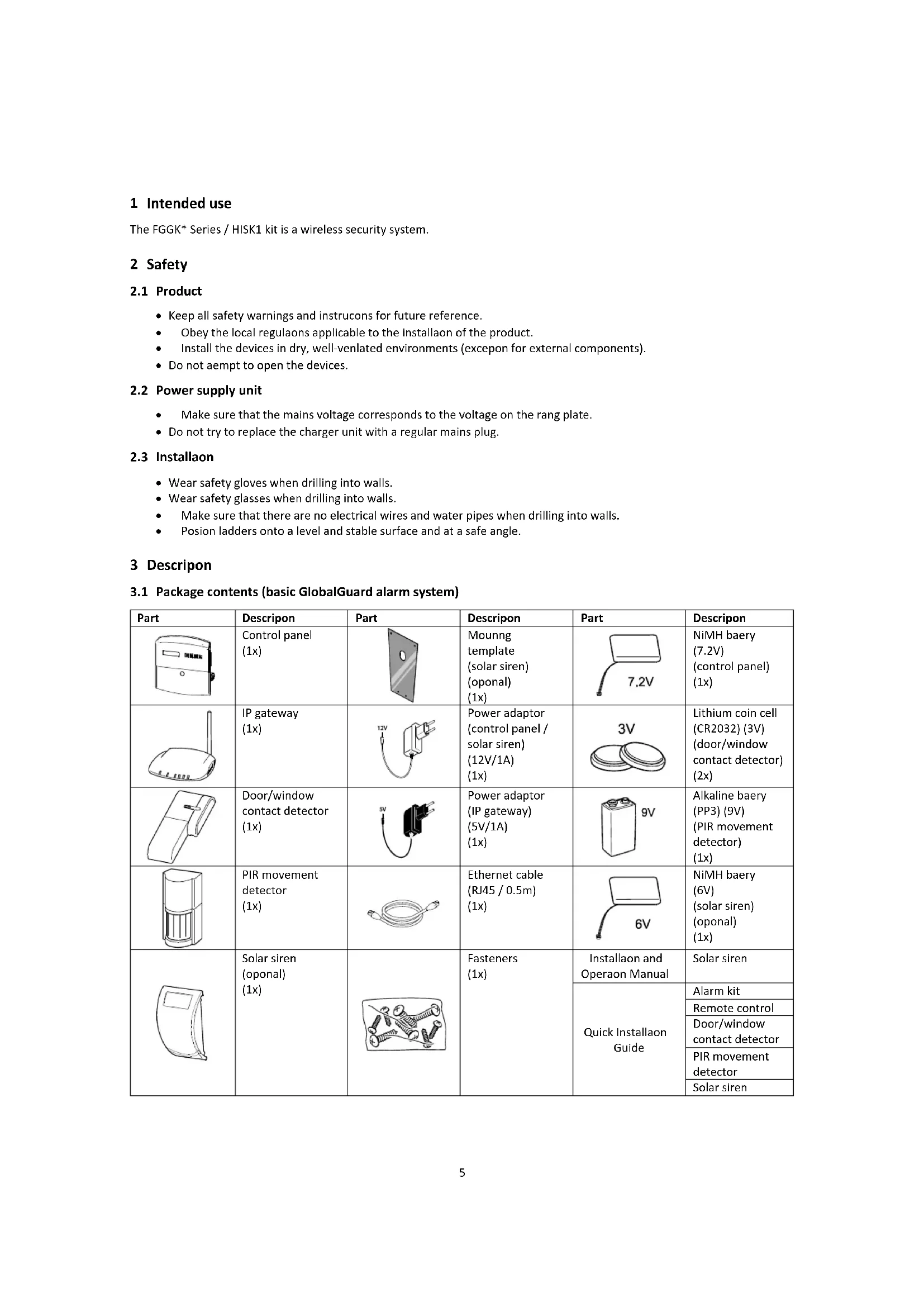
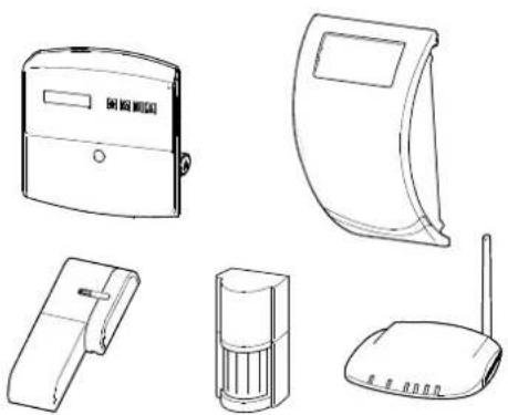
3.1 Package contents (basic GlobalGuard alarm system)
| Part | Descripon | Part | Descripon | Part | Descripon |
| Control panel (1x) | Mounng template (solar siren) (oponal) (1x) | 7.2V | NiMH baery (7.2V) (control panel) (1x) | ||
| IP gateway (1x) | Power adaptor (control panel / solar siren) (12V/1A) (1x) | 3V | Lithium coin cell (CR2032) (3V) (door-window contact detector) (2x) | ||
| Door/window contact detector (1x) | Power adaptor (IP gateway) (5V/1A) (1x) | 9V | Alkaline baery (PP3) (9V) (PIR movement detector) (1x) | ||
| PIR movement detector (1x) | Ethernet cable (RJ45 / 0.5m) (1x) | 6V | NiMH baery (6V) (solar siren) (oponal) (1x) | ||
| Solar siren (oponal) (1x) | Fasteners (1x) | Installaon and Operaon Manual | Solar siren | ||
| Quick Installaon Guide | Alarm kit | ||||
| Remote control | |||||
| Door/window contact detector | |||||
| PIR movement detector | |||||
| Solar siren |
3.2 Required tools
| Tool | Descripon | Tool | Descripon |
| Ear defenders | #2 | Phillips screwdriver (#2) | |
| Safety gloves | Bradawl | ||
| Electric drill | Spirit level | ||
| Masonry drill bit (5 mm) | Pencil | ||
| Masonry drill bit (6 mm) | PC | ||
| Phillips screwdriver (#0) | Router | ||
| Phillips screwdriver (#1) | Internet |
3.3 System requirements
| Operang system | Windows XP / Windows Vista / Windows 7iOS (v4.3.4 or higher):- iPhone 1 / 2 / 3 / 4- iPad 1 / iPad 2 / iPod Touch 4Android (v2.3 or higher):- Android phone (V2.X)- Android tablet (V4.0) |
| Web browser | Internet Explorer 6.x (or higher) |
| Central processing unit (CPU) | Penum 4: 1 GHz (or higher) |
| VGA card resoluon | 800x600 (or higher) |
| Video memory size | 128 Mb (or higher) |
| Internet bandwidth | Upload speed: 512 kbps (recommended upload speed for 1 camera)Download speed: 2 Mbps |
4 Overview
4.1 Control panel
| 4 5 6 7 3 8 | 11 12 9 10 | 1. Home automaon buons (I/II/III) 2. Personal aack buon 3. Display 4. Power indicator 5. Arming mode indicator 6. Event log indicator 7. Personal aack indicator 8. Cover 9. Power adaptor connecn 10. Baery (7.2V) 11. Connecon terminal block 12. Tamper switch |
| Symbol | Item | Status | Funcon |
| Power indicator | On | The mains power is in use. | |
| Flashing | Quick ashing: The baery is in use. Slow ashing: Low baery. | ||
| O | The mains power and the baery are not in use. | ||
| Arming mode indicator | On | The system is set to “Fully Arm”. The system is set to “Holiday Arm”. | |
| Flashing | The system is set to “Part Arm-I”. The system is set to “Part Arm-II”. | ||
| O | The system is set to “Disarm”. | ||
| Event log indicator | On | System message. | |
| Flashing | Alarm memory. | ||
| O | Normal. | ||
| Personal aack indicator | On | The personal aack buon has been pressed. | |
| Flashing | --- | ||
| O | Normal. |
| Symbol | Funcon |
| 0° ... 9° | To enter a specic digit. |
| *° | To enable a funcon (ON).To select an opon (YES). |
| #° | To disable a funcon (OFF).To unselect an opon (NO). |
| ▲ | To move up in the menu. |
| ▼ | To move down in the menu. |
| ESC | To move one level up in the menu. |
| ← | To conrm a selecon. |
| ○ | To set the system to “Fully Arm”.To set the system to “Holiday Arm”. |
| ○ | To set the system to “Part Arm-I”.To set the system to “Part Arm-II”. |
| ○ | To set the system to “Disarm”.To enter test mode. |
| ○ | To enter program mode. |
4.2 IP gateway
| 1. Power indicator / Internet connecon indicator 2. Control panel connecon indicator 3. Camera connecon indicator 4. Link buon |
| Item | Status | Funcon | |
| 1 | Power indicator / Internet connecon indicator | Green | Connecon succeeded. |
| Orange | Connecon failed. | ||
| 2 | Control panel connecon indicator | Green | Connecon succeeded. |
| Orange | Connecon failed. | ||
| 3 | Camera connecon indicator | The 4 indicators indicate the connecon status of up to 8 cameras: - If you connect camera 1-4, indicators 1-4 will become green. - If you add camera 5, indicator 1 will become orange (etc.). - If you disconnect camera 1 but camera 5 is sll acve, indicator 1 will become red (etc.). | |
5 Installaon
Install and operate the alarm system in accordance with the requirements of any current local and naonal regulaons and legislaoon. Contact your authority to obtain details of the local and/or naonal regulaons and legislaoon.
Note: If you install the system for the rst me, change the default master access PIN code and set the correct date and me.
5.1 Installaon example
| 1 | Living room | A | Control panel |
| 2 | Dining room | B | Remote control |
| 3 | Kitchen | C | PIR movement detector |
| 4 | Hall | D | Door/window contact detector |
| 5 | (a) Front door (b) Back door | E | Solar siren |
| 6 | Garage | ||
| 7 | Shed | ||
- Place a rst door/ window contact detector (zone 1) on the front door.
- Place a second door/ window contact detector (zone 2) on the back door.
-
Place a rst PIR movement detector (zone 3) and a second PIR movement detector (zone 4) in two of the following locaons:
-
downstairs in the living room containing most valuables
- on the landing covering the access routes between the bedrooms and the stairs
- in the hall covering the control panel and routes between downstairs rooms
5.2 Device range
The quoted range of the system devices is measured in ideal conditions. Any solid object placed between the transmitter and the receiver will reduce the radio-frequency operang range. The amount by which the wireless range will reduce depends on the obstrucon between the transmitter and the receiver. The eect on the range of mulple walls is cumulave.
| Wall type | Range redocon |
| Dry-lined paron wall | 10-30% |
| Single-layer brick wall | 20-40% |
| Double-layer brick wall | 30-70% |
| Metal panel/radiator | 90-100% |
5.3 Installaon order
- Installing the solar siren (oponal)
Refer to the Installaon and Operaon Manual. Refer to the Quick Installaon Guide.
- Installing the control panel
Refer to the secon "Installing the control panel".
- Installing the IP gateway
Refer to the secon "Installing the IP gateway".
- Installing the PIR movement detector (oponal)
Refer to the Quick Installaon Guide.
- Installing the door/ window contact detector (oponal)
Refer to the Quick Installaon Guide.
- Installing the remote control (oponal)
Refer to the Quick Installaon Guide.
5.4 Installing the control panel

Note: If you use the solar siren as oponal accessory, make sure that the solar siren is installed and its baery is fully charged before installing the control panel.
- Keep the control panel out of reach of young children.
- Mount the control panel to a at surface at a height between 1.5 and 2 metres. Make sure that the tamper switch is closed when you mount the control panel to the wall.
- Locate the control panel in a posion out of sight of potenal intruders, but easily accessible for system operaon and leaving and entering the house within the set alarm me.
- Mount the control panel within a protected area so that potenal intruder cannot reach the control panel without opening a door or window protected by door/window contact detector a or passing through an area protected by a PIR movement detector.
- Locate the control panel such that the exit/entry tone can be heard from outside the property.
- Make sure that the distance from the control panel to the wall socket does not exceed the length of the power supply cable.
- Make sure that the control panel is installed within eecve radio range of the control panel and away from metal objects.
| 1. Pull out the clip and push down the mounng bracket to remove it from the control panel. | |
| 2. Use the mounng bracket as a template to mark the posion of the mounng holes on the wall. 3. Drill mounng holes (5 mm) into the wall according to the marked posions. 4. Insert a supplied wall plug into each mounng hole. | |
| 5. Remove the baery cover. | |
| 6. Make sure that jumper link P1 is in the o posion. 7. Make sure that jumper link P51 is in the o posion. Note: If the tamper alarm of the control panel sounds connuously, reset the alarm: a) Press the button. b) Enter the 4-digit PIN code (User). c) Press the button. | |
| 8. Connect the connector of the NiMH baery (7.2V) to the baery connecn. 9. Install the baery cover. | |
| 10. Connect the white power adaptor (12V) to the power adaptor connecn. Route the cable along the cable track. | |
| 11. Install the control panel to the wall bracket. | |
| If the control panel is powered up and le for 15 minutes, the control panel will emit beeps and the event log indicator will ash to indicate that control panel is searching for the IP gateway. To cancel the beeps and switch o the event log indicator: a) Press the blon. b) Press the blon. | |
| To remove the control panel from the wall: Use a athead screwdriver to push the clip towards the wall and push up the control panel away from the mountng bracket. | |
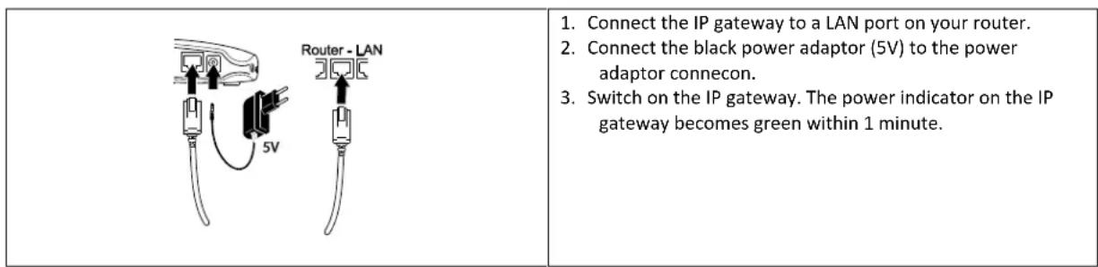
5.5 Installing the IP gateway
The wireless IP gateway allows you to remotely access and control the system over the Internet using the online soware at https://GlobalGuard.Friedland.co.uk or using the Apple/Android GlobalGuard apps. To remotely access the system, the Internet connecn the IP gateway is connected to must be acve. The Internet connecn must be free from any rewalls or other restricons that can prevent remote access.
5.6 Linking the IP gateway to the control panel (oponal)
The supplied IP gateway has been pre-linked to the control panel at the factory.
To link an IP gateway to the control panel:
- Press the button.
- Enter the 4-digit PIN code (User).
- Press the button.
- Select the program mode "5.COMMS". The display shows "5-1 COMMS SETUP".
- Press the buon. The display shows "Input (01-12) Device NO."
- Enter the device number (0-12). Make sure that no other device is already linked to the channel.
- Press the button.
- Select the program mode "2 LEARNING ID". The display shows "WAIT LEARNING...".
- Within 30 seconds, press and hold the link buon on the IP gateway unl the display shows "Learning OK".
5.7 Deleng the IP gateway from the control panel (oponal)
- Press the button.
- Enter the 4-digit PIN code (User).
- Press the button.
- Select the program mode "5.COMMS". The display shows "5-1 COMMS SETUP".
- Press the buon. The display shows "Input (01-12) Device NO."
- Enter the device number (0-12). Make sure that no other device is already linked to the channel.
- Press the button.
- Select the program mode :4 DEVICE REMOVE". The display shows "SELECT YES>*/ NO>#"
- Press the buon.
5.8 Connecon terminal block (oponal)
To access the connecn terminal block, rst put the system into test mode (refer to the secon "Test mode (TEST MODE)".
- Set jumper link P1 to the o posion.
- Switch o the power supply to the power adaptor.
- Remove the control panel from the wall bracket.
- Disconnect the power adaptor from the control panel.
- Remove the baery cover.
- Remove and disconnect the backup baery.
- Wire the connecns to the terminals as required.
- Connect and install the backup baery.
- Install the baery cover.
- Connect the power adaptor to the control panel.
- Switch on the power supply to the power adaptor.
- Install the control panel to the wall bracket.
- Press the button to exit test mode.
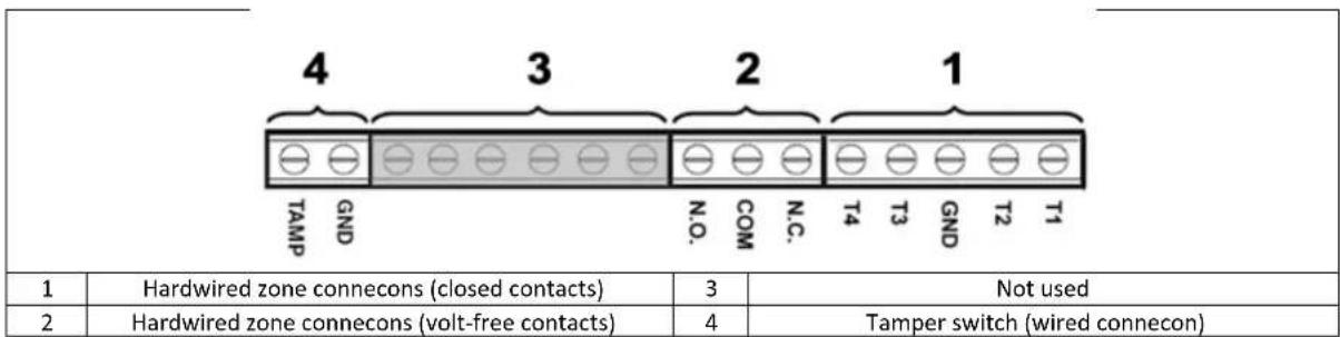
The signaling contacts on all hardwired alarm and tamper zones must be volt free. i.e. they must only open and close and not apply any self-generated voltage across the contacts. The contacts on zones 33, 34, 35 and the tamper circuit must be normally closed. An alarm will be triggered when the contacts open. On zones 33, 34 and 35, additional door/ window contact detectors can be hardwired to these terminals. The contacts on zone 36 must be normally open. An alarm will be triggered when the contacts close.
Note: Jumper link P51 must be normally in the o posion. Set jumper link P51 to the on posion only if the hardwired tamper circuit is used.
5.9 Backward compatibility (security devices)
Earlier versions of 868MHz PIR movement detectors, door/window contact detectors, remote controls and remote keypads devices are also compatible with the system. If you upgrade an existing 868MHz wireless security system, you can use the same security devices by simply linking the security device to the GlobalGuard system.
5.10 Additional wired door/ window contact detector
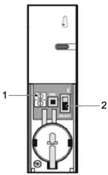
If an additional wired door/ window contact detector is required, wire the detector to the terminal block (1) in the baery compartment. A cable entry cut-out is provided next to the terminal block in the baery cover.
Connect the wired door/ window contact detector using a maximum length of 1.5 metres of any of the following:
- 6-core alarm cable
- 2-core bell wire (min. 6 × 0.2 mm )
2-core 24AWG wire
Use switch SW3 (2) to enable or disable the internal and external wired magnec door/window contact detectors:
| Posion | Funcon |
| Top | Only the internal door/window contact detector is set to the on posion. |
| Boom | Both the internal and external door/window contact detectors are set to the on posion. |
If you use two door/window contact detectors for internal and external connecns simultaneously, only one acvaon event will be counted if one of the contacts is opened. If one door/ window contact detector is le open and the other closed door/ window contact detector is opened, an acvaon event will be counted.
If you do not use the external door/ window contact detector, set switch SW3 to the top position to make sure that the detector operates correctly.
6 Tesng and programming
6.1 Test mode (TEST MODE)
- Make sure that the system is in disarm mode.
- Press the button.
- Enter the 4-digit PIN code (User).
- Press the button.
| TEST MODE | WALK TEST | WAITING... | |
| RF ENVIRONMENT | TEST RF ENVIRONMENT | ||
| SPECTRA LIGHTING TEST | LIGHTS ON FOR 5S, STOP>ESC. | ||
| WIREFREE SIREN SERVICE OFF | SERVICE OFF, WAIT... | ||
| WIREFREE SIREN SERVICE ON | SERVICE ON, WAIT... | ||
| ALARM TEST | RELAY TEST | RELAY ON FOR 5S, STOP>ESC. | |
| WIREFREE SIREN TEST | SIREN ON FOR 5S, STOP>ESC. | ||
| HARDWIRE SIREN TEST | SIREN ON FOR 5S, STOP>ESC. |
6.1.1 Walk test (WALK TEST)
The control panel has a built-in test facility to enable you to test the siren at any me. It is recommended to test your system at regular intervals, but at least once per three months.
Before starng the test, make sure that:
there is no movement for 3 minutes in any area protected by a PIR movement detector.
all doors/windows protected by a door/window contact detector are closed.
- all baery covers and housings are installed correctly.
- Trigger each security detector by walking into an area protected by a PIR movement detector or by opening a door or window protected by a door/window contact detector. The control panel chimes. The display shows the ID code of the zone which the detector is concuured to.
- Remove the baery covers from the PIR movement detectors and the door/ window contact detectors to operate the tamper switches. The control panel chimes. The display shows "ZOX TAMPER".
- Acvate each buon on the remote control (oponal accessory) in turn. The control panel chimes. The display shows a message according to the below table:
| Item | Message |
| 0 | R01 DISARM |
| 0 | R01 PART ARM-1 |
| 0 | R01 FULLY ARM |
| 1 | R01 PANIC |
Note: If a PIR movement detector is at low-baery condion, the control panel will chime and the displays will show "Z0X BATTERY".
6.1.2 RF environment test (RF ENVIRONMENT)
If there is radio frequency interference, the displays will show "ENVIRON . . . POOR".
6.1.3 Wirefree siren service on/o (WIREFREE SIREN SERVICE ON/OFF)
The solar siren has a service mode facility which prevents the tamper switch from triggering an alarm when it is removed from the wall. Before removing the siren from the wall, set the siren to "SERVICE MODE ON". Aer replacing the baeries and installing the siren, set the siren to "SERVICE MODE OFF".
If you select "WIREFREE SIREN SERVICE OFF", the siren will emit one long beep followed by two short beeps.
If you select "WIREFREE SIREN SERVICE ON", the siren will emit two short beeps followed by one long beep.
6.1.4 Alarm test (ALARM TEST)
- Select "RELAY TEST" to operate the external hard-wired relay contacts (NO/NC).
- Select "WIREFREE SIREN TEST" to operate the external solar siren.
- Select 'HARDWIRE SIREN TEST' to operate the control panel siren and the external hard-wired siren.
6.1.5 Reseng the control panel
The control panel will not return to the default factory sengs, but all sengs and learned devices will be erased from memory.
- Press the button.
- Enter the 4-digit PIN code (Admin).
- Press the button.
- Switch o the power supply to the power adaptor.
- Remove the control panel from the wall bracket.
- Disconnect the power adaptor from the control panel.
- Remove the baery cover.
- Remove and disconnect the backup baery.
- Set jumper link P1 to the on position.
- Connect and install the backup baery.
- Install the baery cover.
- Connect the power adaptor to the control panel.
- Switch on the power supply to the power adaptor. The control panel powers up. The display shows "EEPROM RESET". Aer the process is completed, the display shows "DISARM READY".
- Set jumper link P1 to the o posion.
- Install the control panel to the wall bracket.
Note: Aer reseng the control panel, always rst learn the devices into the control panel again.
6.2 Program mode (PROGRAM MODE)
You can set up the system using the instrucons in the manual or using the GlobalGuard PC setup soware available at www.friedlandproducts.com
You can only program home automaon programmes, events and schedules using the PC setup soware. The home automaon buons (I/II/III) on the control panel can only be programmed from the PC setup soware.
If you use the PC setup sware, make sure that the PC is connected to the same router as the router connected to the IP gateway. If you use a wireless connecn, make sure that the PC is within operang range of the router.
- Make sure that the system is in disarm mode.
- Press the button.
- Enter the 4-digit PIN code (Admin).
- Press the buon.
Note: If you use the PC setup sware to change the program sengs, the keypad on the control panel will become inactive (unless you press and hold the ESC buon for 3 seconds).
6.2.1 User setup (USER SETUP)
| PROGRAM MODE | 1. USER SETUP | ||||
| 1-1 ADMIN SETUP | :1 PIN CODE | ENTER PIN: CODE: | |||
| :2 NAME | ENTER NAME | ||||
| :3 REMOTE | :3-1 LEARNING ID | SEND DISARM. WAITING 30 SEC... | |||
| :3-2 PANIC | SELECT ON>*/ OFF># | ||||
| :3-3 STATUS | SELECT ON>*/ OFF># | ||||
| :3-4 DEL DATA | SELECT YES>*/ NO># | ||||
| 1-2 USER1 SETUP | PIN CODE | ENTER PIN: CODE: | |||
| 1-3 USER2 SETUP | PIN CODE | ENTER PIN: CODE: | |||
| 1-4 USER3 SETUP | PIN CODE | ENTER PIN: CODE: | |||
| 1-5 USER4 SETUP | PIN CODE | ENTER PIN: CODE: | |||
| 1-6 USER5 SETUP | PIN CODE | ENTER PIN: CODE: | |||
| 1-7 USER6 SETUP | PIN CODE | ENTER PIN: CODE: | |||
| 1-8 USER7 SETUP | PIN CODE | ENTER PIN: CODE: | |||
| 1-9 DURESS CODE | ENTER PIN: CODE: |
| Default sengs | |
| Item | Message |
| PIN CODE | ADMIN: 1234 |
| NAME | USER 1-7: --- |
| REMOTE | --- |
| DURESS CODE | --- |
6.2.1.1 PIN code (PIN CODE)
You can set dierent PIN codes for dierent items: Admin (ADMIN) / User (USER) / Duress code (DURESS CODE).
6.2.1.2 Duress code (DURESS CODE)
If the system is disarmed using the duress code, the system will disarm as normal. All email contacts in the online account will receive an email alert. All mobile devices running the app will be alerted. The appropriate duress message will be sent.
Note: The duress code can only be entered from the control panel to alert contacts when an occupant enters the property.
6.2.1.3 User name (NAME)
The display shows the user name once the system is armed or disarmed by a specic user. The maximum number of characters for each user name is 15.
- Press the button to toggle between leers and digits.
- Press the button to move the cursor le.
- Press the button to move the cursor right.
- Press the button to delete the character under the cursor.
- Press and hold the button to erase all characters.
| Leers | Digits | Leers | Digits |
| . @ / : - _ → ^ | 1 | PQRS/pQRS | 7 |
| ABC/abc | 2 | TUV/tuv | 8 |
| DEF/def | 3 | WXYZWXYZ | 9 |
| GHI/ghi | 4 | # $ % * + < >< >= [ ] ←→ . | 0 |
| JKL/jkI | 5 | !? -, ';() & " | ¥ | * |
| MNO/mno | 6 | # |
6.2.1.4 Learning the remote control (LEARNING ID)
The control panel can learn up to 8 remote controls.
- Press the Buon on the remote control. The control panel emits two short beeps. The display shows "NEW DEVICE". Note: If the remote control has already been linked, the control panel will emit one long beep.
- Press the buon on the remote control within 15 seconds to conrm the ID code. The control panel emits three short beeps. The display shows "DEVICE CONFIRMED" > "SAVING NEW DEVICE". Note: If the conrmaon signal is not received within 15 seconds, the control panel will emit one long beep and exit learn mode.
| Message | Meaning |
| LEARNING OK | The ID code was learned by the control panel successfully. |
| TIME OUT | If you do not press the buons on the remote keypad within 60 seconds, a me-out will occur. |
| ID DUPLICATE | The same ID code was learned by the control panel beforehand. |
6.2.1.5 Personal aack buon (PANIC)
If you press the personal aack buon () on the remote control, the control panel will generate an alarm.
6.2.1.6 Status (STATUS)
The remote control will control the control panel if the remote control is lost unexpectedly.
6.2.1.7 Deleng the remote control (DEL DATA)
You can delete the sengs of the remote control from the control panel.
6.2.2 System setup (SYSTEM SETUP)
| PROGRAM MODE | 2. SYSTEM SETUP | ||||
| 2-1 ALARM TIME | 10 SEC / 30 SEC / 1 MINUTE / 3 MINUTES / 5 MINUTES / 10 MINUTES | ||||
| 2-2 INT. SIREN | SELECT ON>*/ OFF># | ||||
| 2-3 EXT. SIREN | :3-1 WIREFREE SIREN | :1-1 LINK PANEL TO SIREN | SENDING ID CODE. WAIT 15S. | ||
| :1-2 SIREN WORKING | SELECT ON>*/ OFF># | ||||
| :3-2 NIGHT ALARM | SELECT ON>*/ OFF># | ||||
| 2-4 ERROR BEEP | 10 SEC / 30 SEC / 1 MINUTE / 2 MINUTES / 4 MINUTES / OFF | ||||
| 2-5 RF JAMMING DETECTION | SELECT ON>*/ OFF># | ||||
| 2-6 ALARM RELAY | PULSE 2 SEC / PULSE 30 SEC / PULSE 1 MINUTE / PULSE 3 MINUTES / PULSE 5 MINUTES / ON UNTIL DISARM | ||||
| 2-7 ZONE LOCK | SELECT ON>*/ OFF># | ||||
| 2-8 PART ARM-I SETUP | :9-1 EXIT DELAY | SELECT ON>*/ OFF># | |||
| :9-2 ENTRY DELAY BEEP | SELECT ON>*/ OFF># | ||||
| :9-3 EXIT DELAY BEEP | SELECT ON>*/ OFF># | ||||
| 2-9 PART ARM-II SETUP | :10-1 EXIT DELAY | SELECT ON>*/ OFF># | |||
| :10-2 ENTRY DELAY BEEP | SELECT ON>*/ OFF># | ||||
| :10-3 EXIT DELAY BEEP | SELECT ON>*/ OFF># | ||||
| 2-10 FULLY ARM SETUP | :11-1 EXIT DELAY | SELECT ON>*/ OFF># | |||
| :11-2 ENTRY DELAY BEEP | SELECT ON>*/ OFF># | ||||
| :11-3 EXIT DELAY BEEP | SELECT ON>*/ OFF># | ||||
| 2-11 HOLDAY ARM SETUP | :12-1 EXIT DELAY | SELECT ON>*/ OFF># | |||
| :12-2 ENTRY DELAY BEEP | SELECT ON>*/ OFF# | ||||
| :12-3 EXIT DELAY BEEP | SELECT ON>*/ OFF# | ||||
| 2-12 DATE | DD/MM/YY | ||||
| 2-13 TIME | HH:MM:SS | ||||
| 2-14 WIREFREE KEYPAD | :1 WIREFREE KEYPAD 1 | :1 LEARNING ID | SEND DISARM. WAITING 30 SEC... | ||
| :2 KEYPAD WORK | SELECT ON>*/ OFF># | ||||
| :3 DEL KEYPAD | SELECT YES>*/ NO># | ||||
| :2 WIREFREE KEYPAD 2 | :1 LEARNING ID | SEND DISARM. WAITING 30 SEC... | |||
| :2 KEYPAD WORK | SELECT ON>*/ OFF># | ||||
| :3 DEL KEYPAD | SELECT YES>*/ NO># | ||||
| :3 WIREFREE KEYPAD 3 | :1 LEARNING ID | SEND DISARM. WAITING 30 SEC... | |||
| :2 KEYPAD WORK | SELECT ON>*/ OFF># | ||||
| :3 DEL KEYPAD | SELECT YES>*/ NO># | ||||
| :4 WIREFREE KEYPAD 4 | :1 LEARNING ID | SEND DISARM. WAITING 30 SEC... | |||
| :2 KEYPAD WORK | SELECT ON>*/ OFF># | ||||
| :3 DEL KEYPAD | SELECT YES>*/ NO># | ||||
| :5 WIREFREE KEYPAD 5 | :1 LEARNING ID | SEND DISARM. WAITING 30 SEC... | |||
| :2 KEYPAD WORK | SELECT ON>*/ OFF># | ||||
| :3 DEL KEYPAD | SELECT YES>*/ NO># | ||||
| :6 WIREFREE KEYPAD 6 | :1 LEARNING ID | SEND DISARM. WAITING 30 SEC... | |||
| :2 KEYPAD WORK | SELECT ON>*/ OFF># | ||||
| :3 DEL KEYPAD | SELECT YES>*/ NO># | ||||
| 2-15 LINK PANEL TO SPECTRA | SENDING ID CODE, WAIT 5S. | ||||
| 2-16 LIGHTING SETUP | :1 OPERATING MODE | TIME / 24-HOUR / OFF | |||
| :2 LAMP ON TIME | 1 MINUTE / 3 MINUTES / 5 MINUTES / 10 MINUTES / 30 MINUTES / 60 MINUTES | ||||
| 2-17 LANGUAGE SETUP | :1 ENGLISH | SELECT ON>*/ OFF# | |||
| :2 GERMAN | SELECT ON>*/ OFF# |
| Default sengs | ||
| Item | Message | |
| ALARM TIME | 3 MINUTES | |
| INT. SIREN | ON | |
| EXT. SIREN | WIREFREE SIREN | ON |
| NIGHT ALARM | ON | |
| ERROR BEEP | 30 SEC | |
| RF JAMMING DETECTION | OFF | |
| ALARM RELAY | ON UNTIL DISARM | |
| ZONE LOCK | ON | |
| PART ARM-I SETUP | EXIT DELAY ON 030 SEC | |
| PART ARM-II SETUP | EXIT DELAY ON 030 SEC | |
| FULLY ARM SETUP | EXIT DELAY ON 030 SEC | |
| HOLIDAY ARM SETUP | EXIT DELAY ON 030 SEC | |
| DATE | 01/01/12 | |
| TIME | 12:00:00 | |
| WIREFREE KEYPAD | OFF | |
| LINK PANEL TO SPECTRA | OFF | |
| LIGHTING SETUP | OFF | |
| LANGUAGE SETUP | ENGLISH | |
6.2.2.1 Alarm me (ALARM TIME)
You can set the me for which an alarm will sound aer an alarm has been triggered.
6.2.2.2 Internal siren (INT.SIREN)
You can enable and disable the internal siren.
6.2.2.3 External siren (EXT.SIREN)-Wireless siren (WIREFREE SIREN)
You can enable and disable the external siren.
6.2.2.4 External siren (EXT.SIREN)-Night alarm (NIGHT ALARM)
You can prevent the control panel from iniang a full-alarm condion between 22:00 pm to 6:00 am to avoid the alarm sound disturbing the neighbourhood. If the funcon is disabled, no alarm will sound between 22:00 pm to 6:00 am.
6.2.2.5 Error beep (ERROR BEEP)
If an abnormal condition has occurred, the event log indicator will ash and the control panel will emit an error beep. If the event log indicator ashes while the system is disarmed and the control panel beeps periodically, this indicates an alarm has occurred. Access the event log to make the event log indicator stop ashing and the control panel stop beeping.
Note: The control panel will not emit an error beep between 10:00 pm and 6:00 am.
6.2.2.6 Radio-frequency jamming detecn (RF JAMMING DETECTION)
The radio-frequency jamming detecn will connuously scan for radio-frequency jamming signals on the system operang frequency.
6.2.2.7 Alarm relay (ALARM RELAY)
You can set the me for which the external hard-wired relay contacts will operate aer an alarm has been triggered.
6.2.2.8 Zone lockout (ZONE LOCKOUT)
You can prevent a single zone from triggering an alarm more than three mes before the system is disarmed.
6.2.2.9 Part arm-I setup (PART ARM-I SETUP)
You can set how long the exit delay expires when the system is armed as "Part Arm-I" mode.
6.2.2.10 Part arm-II setup (PART ARM-II SETUP)
You can set how long the exit delay expires when the system is armed as "Part Arm-II" mode.
6.2.2.11 Fully arm setup (FULLY ARM SETUP)
You can set how long the exit delay expires when the system is armed as "Fully Arm" mode.
6.2.2.12 Holiday arm setup (HOLIDAY ARM SETUP)
You can set how long the exit delay expires when the system is armed as "Holiday Arm" mode.
6.2.2.13 Date (DATE)
You can set the current date.
6.2.2.14 Time (TIME)
You can set the current me.
6.2.2.15 Remote keypad (WIREFREE KEYPAD)
The control panel can learn up to 6 remote keypads.
1. Learning the remote keypad (LEARNING ID)
a) Enter the 4-digit ID code and press the buon on the remote keypad. The control panel emits two short beeps. The display shows "NEW DEVICE".
Note: If the remote control has already been linked, the control panel will emit one long beep.
b) Enter the 4-digit ID code and press the buon on the remote keypad within 15 seconds to conrm the ID code. The control panel emits three short beeps. The display shows "DEVICE CONFIRMED" > "SAVING NEW DEVICE".
Note: If the conrmaon signal is not received within 15 seconds, the control panel will emit one long beep and exit learn mode.
| Message | Meaning |
| LEARNING OK | The ID code was learned by the control panel successfully. |
| TIME OUT | If you do not press the buons on the remote keypad within 60 seconds, a me-out will occur. |
| ID DUPLICATE | The same ID code was learned by the control panel beforehand. |
2. Enabling and disabling the remote keypad (KEYPAD WORK)
You can enable and disable a remote keypad.
3. Deleng the remote control (DEL KEYPAD)
You can delete the sengs of the remote keypad from the control panel.
6.2.2.16 Linking the control panel to the Spectra lightng receiver (LINK PANEL TO SPECTRA) (oponal)
When the Spectra receiver is in test mode, press the buon to link the control panel to the Spectra lighng receiver.
6.2.2.17 Lightng setup for Spectra lightng receiver (LIGHTING SETUP) (oponal)
You can set the operon mode (OPERATION MODE) and the lamp-on me (LAMP-ON TIME) for the Spectra lighting receiver.
If the control panel is linked to a Spectra lighng receiver and the Spectra lighng control is enabled, any alarm condion (except re alarms) will switch the linked lighng on for the set light-on duraon.
Note: You can only set the start me and stop me from the GlobalGuard PC setup soware.
If the Spectra lighng is concured as 24-hour, the lights will be triggered at any me an alarm occurs. If the Spectra lighng is concured as me-controlled, the lights will only be triggered if the alarm occurs before the programmed stop me or aer the programmed start me. If the alarm occurs between the stop me and the start me, the lights will not be triggered.
6.2.2.18 Language setup
You can set the display language for the control panel.
Note: The control panel may only display the English language. The German language is subject to be added in the near future.
6.2.3 Security detector zone setup (SECURITY DETECTOR ZONE)
| PROGRAM MODE | 3. SECURITY DETECTOR ZONE | ||||
| Wireless detector zones: | 3-1 WIRELESS DETECTOR ZONE | INPUT (01-32) DETECTOR ZONE | :1 LEARNING ID | SEND CODE, WAITING 305... | |
| Wired detector zones: | 3-2 WIRED DETECTOR ZONE | INPUT (33-36) DETECTOR ZONE | :1 WIRED ZONE | ||
| :2 LOCATION | NONE / FRONT DOOR / BACK DOOR / PATIO DOOR / DINING ROOM / LIVING ROOM / LOUNGE / STUDY / PLAY ROOM / KITCHEN / UTILITY ROOM / HALL / LANDING / BEDROOM 1 / BEDROOM 2 / BEDROOM 3 / BEDROOM 4 / BEDROOM 5 / SHED / GARAGE / PIR / MAG / SMOKE 1 / SMOKE 2 / SMOKE 3 | ||||
| :3 MODEL TYPE | PIR DETECTOR / DOOR CONTACT / FIRE/SMOKE / FLOOD DETECTOR / GAS DETECTOR / CO DETECTOR / EMERGENCY UNIT | ||||
| :4 SECURITY TYPE | INTRUDER / 24 HR INTRUDER / FIRE / TEST / PANIC/PA | ||||
| :5 CHIME MODE | SELECT ON>*/ OFF># | ||||
| :6 PART-ARM-I | SELECT ON>*/ OFF># | ||||
| :7 PART-ARM-II | SELECT ON>*/ OFF># | ||||
| :8 DETECTOR STATUS | SELECT ON>*/ OFF># | ||||
| :9 DETECTOR REMOVE | SELECT YES>*/ NO># | ||||
| :10 SIREN AT TRIGGER | SELECT ON>*/ OFF># | ||||
| :11 ENTRY DELAY | SELECT ON>*/ OFF># |
| Default sengs | ||
| Item | Message | |
| LEARNING ID | — | |
| WIRED ZONE | OFF | |
| LOCATION | NONE | |
| MODEL TYPE | NONE | |
| SECURITY TYPE | INTRUDER | |
| CHIME MODE | OFF | |
| PART-ARM-I | OFF | |
| PART-ARM-II | OFF | |
| DETECTOR STATUS | OFF | |
| DETECTOR REMOVE | — | |
| SIREN AT TRIGGER | ON | |
| ENTRY DELAY | Zones 1-2 | DELAYED 030 SECONDS |
| Zones 3-36 | INSTANT 030 SECONDS | |
6.2.3.1 Learning the security detector (LEARNING ID)
The control panel can learn up to 32 wireless 868MHz door-window contact detectors or PIR movement detector detectors. The control panel can learn up to 4 wired security detectors.
- Press the tamper switch on the security detector.
- Aer 2 seconds, press the tamper switch on the security detector again to conrm the ID code.
Note: If the conrmaon signal is not received within 15 seconds, the control panel will emit one long beep and exit learn mode.
Note: If the security detector has already been linked, the control panel will emit one long beep.
| Message | Meaning |
| LEARNING OK | The ID code was learned by the control panel successfully. |
| TIME OUT | If you do not press the tamper switch on the security detector within 60 seconds, a me-out will occur. |
| ID DUPLICATE | The same ID code was learned by the control panel beforehand. |
6.2.3.2 Locoan (LOCATION)
You can set the locaon for the security detector.
6.2.3.3 Model type (MODEL TYPE)
You can set the model type for the security detector.
6.2.3.4 Security type (SECURITY TYPE)
You can set the security type for the security detector.
| Security type | Funcon |
| INTRUDER | Standard intruder monitoring with arming funcons. |
| 24 HR INTRUDER | 24-hour monitoring of areas requiring connuous security protecon, even when the system is disarmed. If a security detector is acvated, a full-alarm condion will be initiated immediately. |
| FIRE | 24-hour monitoring of all re/smoke detectors connected to the system. If a security detector is acvated, a full-alarm condion will be initiated immediately. |
| TEST | When the system is armed, any detector setup will not initiate an alarm, but will generate an event in the event log. All email contacts in the online account will receive an email alert. All mobile devices running the app will be alerted. |
| PANIC/PA | The same ID code was learned by the control panel beforehand. |
6.2.3.5 Chime mode (CHIME MODE)
You can enable and disable the chime mode for a security detector.
6.2.3.6 Part arm-I setup (PART-ARM-I)
You can acvate and deacvate the detector zone when the system is set to "Part Arm-I".
6.2.3.7 Part arm-II setup (PART-ARM-II)
You can acvate and deacvate the detector zone when the system is set to "Part Arm-II".
6.2.3.8 Detector status (DETECTOR STATUS)
You can enable or disable operaoon of the security detector.
6.2.3.9 Deleng the security detector (DETECTOR REMOVE)
You can delete the sengs of the security detector from the control panel.
6.2.3.10 Siren at trigger (SIREN AT TRIGGER)
You can set whether the control panel will sound or become silent when the security detector is triggered.
6.2.3.11 Entry delay (ENTRY DELAY)
You can set the entry delay for the system when the system is armed. The entry delay is the me between triggering a security detector configured with a delay and the alarm occurring. The entry delay acts all arming modes and is no longer controllable for individual arming modes.
6.2.4 Home automon setup (HOME AUTO.)
| PROGRAM MODE | 4. HOME AUTO. | ||||
| 4-1 HOME AUTO.CONTROL SETUP | INPUT (01-32) CONT.NUMBER | :1 LINK PANEL TOCONTROL | SENDING ID CODE.WAIT 2S. | ||
| :2 ALL ON | SELECT ON>*/ OFF># | ||||
| :3 REMOTE ACCESS | SELECT ON>*/ OFF># | ||||
| :4 MODEL TYPE | DIMMER/SWITCH DEVICE/CURTAIN SWITCH | ||||
| :5 CONT. STATUS | SELECT ON>*/ OFF># | ||||
| :6 CONT. REMOVE | SELECT YES>*/ NO># | ||||
| 4-2 HOME AUTO.REMOTE/SENSOR | INPUT (01-32) DEVICENUMBER | :1 LEARNING ID | WAIT LEARNING... | ||
| :2 DEVICE STATUS | SELECT ON>*/ OFF># | ||||
| :3 DEVICE REMOVE | SELECT YES>*/ NO># |
| Default sengs | |
| Item | Message |
| HOME AUTO. CONTROL SETUP | |
| LINK PANEL TO CONTROL | --- |
| ALL ON | OFF |
| REMOTE ACCESS | ON |
| MODEL TYPE | NONE |
| CONT. STATUS | OFF |
| CONT. REMOVE | --- |
| HOME AUTO. REMOTE/SENSOR | |
| LEARNING ID | --- |
| DETECTOR STATUS | OFF |
| DETECTOR REMOVE | --- |
6.2.4.1 Home automon control setup (receiver-type of devices) (HOME AUTO. CONTROL SETUP)
The feature concerns the use of receiver-type of devices only.
6.2.4.1.1 Learning the receiver (LINK PANEL TO CONTROL)
The control panel can learn up to 32 home automaon control receivers.
- Press and hold the learn buon on the receiver for 3 seconds. The learn indicator ashes quickly. The learn indicator on the receiver stops ashing when the ID code of the control panel is conrrmed.
| Message | Meaning |
| SENDING ID CODE WAIT 2S | The ID code was emied from the control panel. |
| WAIT 2 SECOND TEST | The ID code was learned by the receiver. The receiver switches on and o once automacally. |
6.2.4.1.2 Switching on and o all receivers (ALL ON)
You can switch on and o all home automaon control receivers of the group.
6.2.4.1.3 Remote access (REMOTE ACCESS)
You can enable and disable remote access to and control of the home automon control receivers.
Example: If the home automaton control receiver is connected to a coee maker and the remote access is set to "ON", the coee maker will switch to "ON" through the online GlobalGuard soware or through the GlobalGuard app.
Note: If the appliance connected to the home automaon control receiver requires your aenon during operaon, set the remote access to "OFF".
6.2.4.1.4 Model type (MODEL TYPE)
You can set the model type for the home automaon control.
6.2.4.1.5 Home automon control status (CONT. STATUS)
You can enable or disable operon of the home automaon control receiver.
6.2.4.1.6 Deleng the home automaon control (CONT. REMOVE)
You can delete the sengs of the home automaon control receiver from the control panel.
6.2.4.2 Home automaon control setup (transmier-type of devices) (HOME AUTO. REMOTE/SENSOR)
The feature concerns the use of transmitter-type of devices only.
6.2.4.2.1 Learning the transmier (LEARNING ID)
The control panel can learn up to 32 home automaon control transmiers.
- Press and hold the learn buon on the transmier for 3 seconds.
| Message | Meaning |
| LEARNING OK | The ID code was learned by the control panel successfully. |
| TIME OUT | If you do not press the learn buoyon on the transmitier within 30 seconds, a me-out will occur. |
| ID DUPLICATE | The same ID code was learned by the control panel beforehand. |
6.2.4.2.2 Device status (DEVICE STATUS)
You can enable or disable operon of the home automaon control transmier.
6.2.4.2.3 Deleng the device (DEVICE REMOVE)
You can delete the sengs of the home automaon control transmier from the control panel.
6.2.5 Communicacon device setup (COMMS)
The feature concerns the use of transceiver-type of devices only. Transceiver-type of devices are used to communicate with the control panel in order to allow remote access, control and conguraon.
Note: The supplied IP gateway, pre-linked to the control panel, is an example of a communicaon device.
| PROGRAM MODE | 5. COMMS | ||||
| 5-1 COMMS SETUP | INPUT (01-12)C DEVICE NO. | :1 MODEL TYPE | |||
| :2 LEARNING ID | WAIT LEARNING... | ||||
| :3 DEVICE STATUS | SELECT ON>*/ OFF># | ||||
| :4 DEVICE REMOVE | SELECT YES>*/ NO># |
| Default sengs | |
| Item | Message |
| MODEL TYPE | --- |
| LEARNING ID | --- |
| DEVICE STATUS | OFF |
6.2.5.1 Model type (MODEL TYPE)
You can set the model type for the communicaon device.
6.2.5.2 Learning the transceiver (LEARNING ID)
The control panel can learn up to 12 communicaon devices.
- Press and hold the learn buoy on the transceiver for 3 seconds.
| Message | Meaning |
| LEARNING OK | The ID code was learned by the control panel successfully. |
| TIME OUT | If you do not press the learn buoyon on the transceiver within 30 seconds, a me-out will occur. |
| ID DUPLICATE | The same ID code was learned by the control panel beforehand. |
6.2.5.3 Device status (DEVICE STATUS)
You can enable or disable operon of the communicaon device.
Note: The device status automatically changes to "ON" aer a communicaon device is linked to the control panel.
6.2.5.4 Deleng the device (DEVICE REMOVE)
You can delete the sengs of the communicaon device from the control panel.
6.2.6 Backup and Restore (BACKUP & RESTORE)
| PROGRAM MODE | 6. BACKUP & RESTORE | ||
| 6-1 BACKUP. DD/MM/YY. | SELECT YES>*/ NO=# | ||
| 6-2 RESTORE. DD/MM/YY. | SELECT YES>*/ NO=# |
| Default sengs | |
| Item | Message |
| BACKUP | DD/MM/YY (today) |
| RESTORE | -- |
6.2.6.1 Backup (BACKUP)
You can save the current sengs in the control panel for backup purposes.
If required, you can restore the saved sengs.
7 Operaon
When leaving the premises, the system must be armed. Before arming the system, make sure that all doors and windows are locked and that the available PIR movement detectors are not obstructed. Make sure that animals are restricted to areas not protected by PIR movement detectors.
The system has four arming modes: "Fully Arm", "Holiday Arm", "Part Arm-I" and "Part Arm-II".
The "Holiday Arm" mode is a duplicate of the "Fully Arm" mode. The "Fully Arm" mode is commonly used daily, whereas the "Holiday Arm" mode is used when away on holiday for a longer period. For the "Holiday Arm" mode particularly, you can set up schedules or events to operate any home automon control receiver to simulate the presence of occupants. For details on seng up schedules or events, refer to the soware manual.
"Part Arm-I" and "Part Arm-II" allow for selected detectors or zones to be disarmed while other detectors or zones are armed.
When the system is armed, the display shows the arming mode and the programmed exit delay count down. If the exit delay beeps are enabled, the control panel will emit beeps with the beep rate increasing in steps as the exit delay expires. At the end of the exit period, all ave zones are fully armed. The user must have le the premises and closed the nal protected door.
When the system is armed and a detector on an acve zone is triggered, the display shows the programmed entry delay for the zone counting down. If the entry delay beeps are enabled, the control panel will emit beeps with the beep rate increasing in steps as the entry delay expires. If the system has not been disarmed when the entry delay expires, a full alarm will occur.
Details of the zone event that triggered the alarm are recorded in the event log.
At the end of the alarm me, the alarms will stop and the system will re-arm itself automatically (subject to the conditions of the zone lockout feature).
7.1 Fully arming the system ("Fully Arm" mode)
7.2 Holiday arming the system ("Holiday Arm" mode)
7.3 Part-arming the system
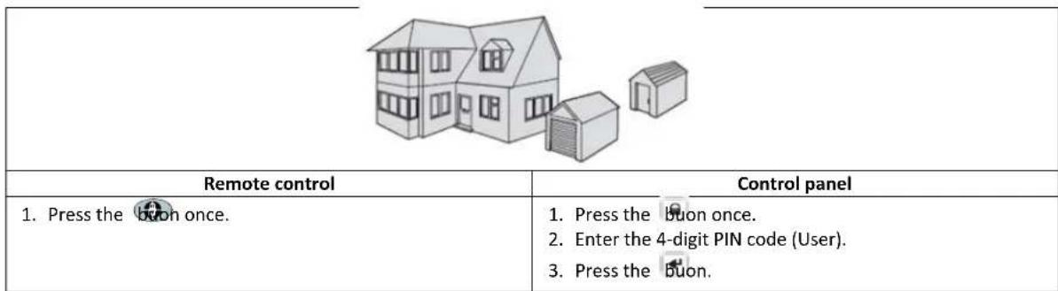
7.3.1 "Part Arm-I" mode
| Remote control | Control panel |
| 1. Press the button once. | 1. Press the button once. 2. Enter the 4-digit PIN code (User). 3. Press the button. |
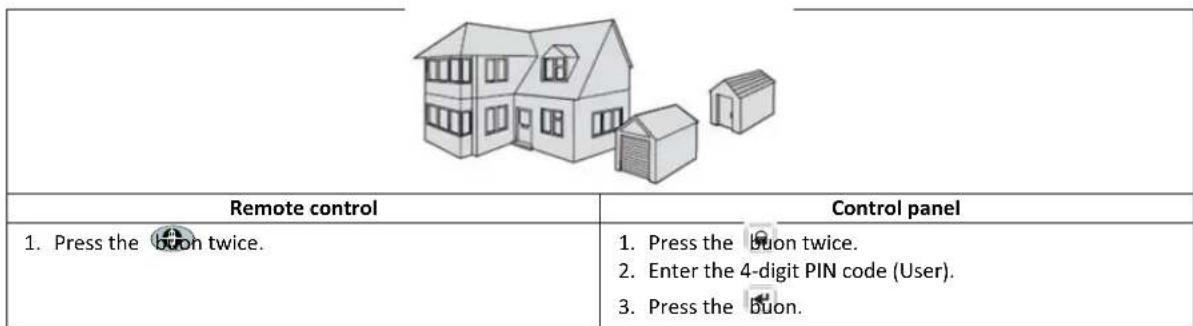
7.3.2 "Part Arm-II" mode
| Remote control | Control panel |
| 1. Press the button twice. | 1. Press the button twice. 2. Enter the 4-digit PIN code (User). 3. Press the button. |
7.4 Disarming the system ("Disarm" mode)
| Remote control | Control panel |
| 1. Press the buon once. | 1. Press the buon once. 2. Enter the 4-digit PIN code (User). 3. Press the buon. |
Note: If the control panel is linked to a Spectra lightng receiver and the Spectra lightng control is enabled, any alarm condion (except re alarms) will cause the linked lightng to be switched on for the set lamp-on me.
If the system is disarmed using the duress code, the system will disarm as normal. All email contacts in the online account will receive an email alert. All mobile devices running the app will be alerted. The appropriate duress message will be sent.
7.5 Quick-seng funcon
The quick-seng funcon fully arms the system with a 10-second exit delay.
- Press the Buon.
- Enter the 4-digit PIN code (User).
- Press the Buon.
Note: If you press the 0°buon during the exit-delay period of any arming mode, the remaining exit-delay period will be reset to 5 seconds.
7.6 Home automon buons (I/II/III)
The home automon buons on the control panel are used to operate the "Programmes" setup from in the PC setup soware. Refer to the soware manual.
Note: If you press a home automaon buon, wait for a few seconds before pressing another buon. The programme may not be acvated if you press the buons too quickly.
7.7 Personal aack facility
The user can trigger an alarm at any me in the event of threat or danger by acvang the personal aack facility.
| Remote control | Control panel |
| 1. Press and hold the button for 3 seconds. | 1. Press and hold the personal aack buon for 3 seconds. |
| The alarm will connue for the alarm duraon when the system will automatically reset or unl the system is disarmed. | |
7.8 Zone lockout
If, while the system is armed, a single zone triggers an alarm more than three mes and zone lockout is enabled, the zone will be locked out. The siren will ignore other alarm signals from the zone. An alarm will not be triggered. The zone lockout will be cancelled when the siren is disarmed. If zone lockout is disabled, a single zone can initiate any number of alarms. Zone lockout operates with alarm zones only. Zone lockout does not operate with re zones.
7.9 Device tamper
The tamper zone operates on a 24-hour basis. Receipt of a tamper signal from any device will immediately trigger an alarm irrespective of systems armed/disarmed status unless the system is in test mode or program mode.
If the baery cover of any device (except remote controls) is removed or if the siren or the control panel is removed from the wall, an alarm will occur immediately even if the system is disarmed (unless the system is in test mode or program mode). The alarm will sound unl the set alarm me expires or the system is disarmed from the remote control or the remote keypad.
7.10 Chime facility
You can only operate the chime facility with the system in standby mode.
- Press the button to enable the chime facility.
- Press the on again to disable the chime facility.
Note: To operate the chime facility using a security detector, set the chime mode for the zone of the security detector to "ON".
7.11 Spectra lighng (manual/automac switching)
- Press the Buon to switch the linked Spectra lighng ON.
- Press the 5° buon to switch the linked Spectra lighng OFF and back to automac operaoa.
7.12 Keyboard beeps
- Press the Buon to mute the keyboard beeps.
- Press the Buon again to unmute the keyboard beeps.
7.13 Entry/exit delay beeps
If the entry/exit delay beeps are enabled, you can temporarily disable them during the acve delay period only.
- Press the Buon to mute the entry/exit delay beeps.
- Press the 3^th buon again to unmute the entry/exit delay beeps.
Note: When the next entry/exit delay period starts, the beeps will follow the main system seng as normal.
7.14 Event log
The event log indicator ashes every 5 seconds to indicate that a new event entered into the event log. Only alarm events will cause the control panel to beep every 10 seconds. Other system events (e.g. low-baery condion) will not iniate the warning beeps.
Take one of the following acons:
- Press the buon to switch o the event log indicator.
- Press the buo8 to read the event message in the event log.
Each event message is shown on two displays. The rst display shows the event number and when the event occurred. The second display shows the actual content of the event.
| Message | Descripon | Message | Descripon |
| EVENT LOG KEY IN UP/DOWN | Message display | TAMPER | Control panel Tamper |
| EVENT XXX MM/DD HH:MM:SS | Event xxx Date & Time | COMMS DEVICE NO.XX TAMPER | Communicaon device Tamper |
| NO EVENT | No event | COMMS DEVICE XX INACTIVE | Communicaon device Connecon failure |
| PANIC SIREN | The personal aack buon on the control panel has been triggered. | CONTROL PANEL LOW BATTERY | Control panel Low baery |
| WIREFREE KEYPAD PANIC SIREN | The panic siren has been triggered by the wireless keypad. | COMMS DEVICE XX LOW BATTERY | Communicaon device xx Low baery |
| [LOCATION] ZXX PANIC/PA | The panic siren has been triggered by zone xx. | REMOTE/DETECTOR XX LOW BATTERY | Remote/Sensor device xx Low baery |
| USERXX RXX PANIC SIREN | The panic siren has been triggered by user xx. | [LOCATION] ZXX LOW BATTERY | Zone sensor xx Low baery |
| [LOCATION] ZXX INTRUDER | Intruder warning | RF JAMMED | The radio frequency is being jammed. |
| [LOCATION] ZXX FIRE | Fire warning | CONTROL PANEL AC POWER LOSS | Control panel Lost AC power |
| FULLY ARM USERXX | Fully Arm by user xx. | COMMS DEVICE XX AC POWER LOSS | Communicaon device xx Lost AC power |
| HOLIDAY ARM USERXX | Holiday Arm by user xx. | SCHEDULE FUNC. NO.XX TRIGGER | Schedule funcon xx is triggered. |
| PART-ARM-I USERXX | Part Arm-I by user xx. | EVENT FUNC. NO.XX TRIGGER | Event funcon xx is triggered. |
| PART-ARM-II USERXX | Part Arm-II by user xx. | PROG. FUNC. NO.XX TRIGGER | Programme funcon xx is triggered. |
| DISARM USERXX | Disarm by user xx. | [LOCATION] ZXX TEST | Zone trigger (Zone type is "Test") |
| [LOCATION] ZXX TAMPER | Zone sensor Tamper | WIREFREE KEYPAD XX LOW BATTERY | Wireless keypad xx Low baery |
| TAMPER WIREFREE KEYPAD | Wireless keypad Tamper | USERXX RXX LOW BATTERY | Remote control xx Low baery |
7.15 Baery monitoring
7.15.1 Low-baery condion
All system devices connuously monitor their baery condion. When the low-baery indicator on a device comes on, replace the baery for the device as soon as possible. Before replacing the baery, switch the system into test mode. Aer replacing the baery, switch the system back into operang mode.
If a door/ window contact detector or a PIR movement detector has a low-baery condion, the condion will be recorded by the control panel and an event message will be stored in the event log.
7.15.2 Control panel
If the power supply is interrupted, the control panel will be powered by the rechargeable main baery. Under normal-baery conditions, the power indicator will ash at 1-second intervals. Under low-baery, the power indicator will ash at 3-second intervals.
7.15.3 Remote control
Under low-baery conditions, the transmit indicator will connue to ash aer the buon has been released. Under normalbaery conditions, the transmit indicator will go o within 2 seconds aer the buon has been released.
7.15.4 Door/ window contact detector
Under low-baery conditions, the transmit indicator will come on for 1 second aer the door or the window has been opened. Under normal-baery conditions, the transmit indicator will not come on (unless the detector is in test mode with the baery cover removed).
7.15.5 PIR movement detector
Under low-baery conditions, the indicator behind the detector lens will ash when movement is detected. Under normalbaery conditions, the indicator behind the detector lens will not come on (unless the detector is in walk-test mode).
8 Maintenance
8.1 Replacing the baeries
8.1.1 Control panel
Do not leave the rechargeable main baeries in a discharged state for long periods. The rechargeable main baeries have a typical life of 3-4 years and do not require any maintenance.
Replacement baeries: 6V NiMH baery (1x)
8.1.2 Remote control
The remote control requires life maintenance. Replace the baeries once a year or when a low-baery condion is indicated.
Replacement baeries: 3V CR2032 lithium coin cell (1x)
8.1.3 Remote keypad
The remote keypad requires life maintenance. Replace the baeries once a year or when a low-baery condion is indicated.
Replacement baeries: 9V PP3 alkaline baery (1x)
8.1.4 Door/window contact detector
The door/ window contact detector requires life maintenance. Replace the baeries once a year or when a low-baery condion is indicated.
Replacement baeries: 3V CR2032 lithium coin cell (2x)
Note: Do not use rechargeable baeries with door/ window contact detectors.
8.1.5 PIR movement detector
The PIR movement detector requires life maintenance. Replace the baeries once a year or when a low-baery condion is indicated.
Replacement baeries: 9V PP3 alkaline baery (1x)
Note: Do not use rechargeable baeries with PIR movement detectors.
8.1.6 Solar siren
If you must power down the system completely, rst switch the control panel into test mode and then switch the siren into service mode before removing the siren cover and disconnecting the rechargeable main baery and the inial power-up baery. Make sure that the solar panel is covered with a lightproof material to prevent the solar panel from powering the siren. Aer installing the siren, switch the siren back into operang mode to re-arm the siren.
- Clean the solar panel using a so, damp cloth every 6 months, preferably in spring and autumn. Do not use abrasive, solvent-based or aerosol cleaners. Do not clean the inside of the siren or allow water to enter the siren to make sure that the solar panel keeps receiving all the available light.
- Do not leave the siren for long periods with the baeries connected, unless the siren is able to receive sucent light to maintain the baery charge. If the baery charge is not maintained, the rechargeable main baery will run unacceptably low and the siren must be recharged from the 12Vdc/1A power supply of the control panel. Install a new inial power-up baery to make sure that the siren receives sucent power until the solar panel can recharge the main baery.
- Do not leave the rechargeable main baery in a discharged state for long periods. The rechargeable main baery has a typical life of 3-4 years and does not require any maintenance.
Replacement baeries: 7.2V NiMH baery (1x) / 9V PP3 alkaline baery (1x)
9 Troubleshoong
| Problem | Soluon |
| The rst two indicators on the IP gateway remain orange and do not stabilise to green. | Make sure that the Internet connecion is acve and not restricted.Make sure that the control panel is on.Make sure that the IP gateway is within operang range of the control panel. The RF indicator on the IP gateway will remain orange if the IP gateway is not within operang range of the control panel. |
| The control panel does not work.The power indicator is o or ashes. | Mains power failure: Check whether other electrical circuits are operable.Make sure that the power adaptor is connected to the control panel.Make sure that the power adaptor is connected to the wall socket (and the wall socket is switched on). |
| The event log indicator on the control panel ashes. | Read the event message.Check whether the available remote controls have a low-baery condion. If necessary, replace the baeries.Check whether the available remote keyboards have a low-baery condion. If necessary, replace the baeries.Check whether the available door/window contact detectors have a low-baery condion. If necessary, replace the baeries.Check whether the available PIR movement detectors have a low-baery condion. If necessary, replace the baeries. |
| The control panel does not accept the 4-digit PIN code(User). | Enter the correct 4-digit PIN code (User).Do not wait for more than 5 seconds between pressing the digit buonsRESET to factory defaults and reprogram the system. |
| A defecon zone is triggered, but no alarm sounds. | The entry/exit delay is not yet expired.The alarm me has expired and the system has reset.The alarm me has been programmed to "NO ALARM". |
| The siren and the indicators are operang, but no alarm sounds. | Make sure that the siren is mounted to the wall correctly and the tamper switch is fully pressed. |
| The siren does not respond to the control panel. | Enter the correct 4-digit PIN code (User).Make sure that the ID code of the siren is learned by the control panel.Make sure that DIP switch 5 of the siren is set to "SIREN".Make sure that the siren is installed within eecve radio range of the control panel and away from metal objects.Make sure that the siren is set to "SERVICE MODE OFF".The rechargeable main baery of the siren is discharged:1. Clean the solar panel.2. Replace the baery if it is at the end of its useful life. If necessary, rst charge the baery for 4 hours. |
| A full alarm sounds while the system has not been triggered by an intruder or is disarmed. | Tamper switch acvaon1. Make sure that baery covers of all security detectors are installed correctly.2. Make sure that the siren is mounted to the wall correctly and the tamper switch is fully pressed.The personal aack alarm has been operated from the control panel or from a remote control.The an-jamming defecon circuit has been operated. |
| The indicator on the remote control is o or dim when the remote control is operated. | Make sure that the baery is installed with correct polarity.Make sure that the baery holder connecons make good contact with the baery.Low baery. Replace the baery. |
| The PIR movement detector gives a false alarm. | Do not install the detector near in direct sunlight or near heat sources.Do not install the detector in humid surroundings.The sensitivity of the detector is too high. Set switch SW3 of the detector to "LOW". |
| The indicator on the PIR movement detector ashes on defecon of movement. | The detector is sill in walk-test mode for xed 5 minutes aer the PCB buon has been avated.Low baery. Replace the baery. |
| The PIR movement detector does not detect any movement to acvate the alarm. | If the PIR movement detector has already detected movement in the last 2 minutes, wait for another 2 minutes before moving in front of the detector. The PIR movement detector goes to sleep for 2 minutes to conserve baery power aer each me movement is detected. |
| The door/window contact detector does not work. | Make sure that the magnet is posioned correctly in relaon to the detector, with a gap of less than 10 mm between the magnet and the detector. Make sure that the baeries are installed with correct polarity. Make sure that the baery holder connecns make good contact with the baeries and the circuit board. Make sure that the ID code of the detector is learned for a parcular zone. If an additional door/window contact detector is connected:1. Make sure that both contacts are closed.2. Make sure that the additional contact is correctly wired and that switch SW3 of the detector is set to “INT./EXT.”. Make sure that the detector is installed within eecve radio range of the control panel and away from metal objects. |
| The door/window contact detector gives a false alarm. | Make sure that the magnet is posioned correctly in relaon to the detector, with a gap of less than 10 mm between the magnet and the detector. The tamper switch below the baery cover is not acvated. Make sure that the baery cover is installed correctly. |
| The indicator on the door/window contact is on when a door or window is opened. | Low baery. Replace the baery. |
10 Technical data
| Control panel | |
| Radio frequency | 868 MHz / 433 MHz |
| Communicaon range | 868 MHz: 125 m (in open space) / 433 MHz: 50 m (in open space) |
| Dimensions (LxWxD) | 215 x 215 x 47 mm |
| Siren | 95 dB (Piezo) |
| Remote control | |
| Radio frequency | 868 MHz |
| Communicaon range | 150 m (in open space) |
| Dimensions (LxWxD) | 65 x 36 x 13 mm |
| Baery life | >1 year |
| IP gateway | |
| Radio frequency | 868 MHz |
| Communicaon range | 150 m (in open space) |
| Dimensions (LxWxD) | 34.5 x 176.5 x 124.8 mm |
| Door/window contact detector | |
| Radio frequency | 868 MHz |
| Communicaon range | 150 m (in open space) |
| Dimensions (LxWxD) | 100 x 29 x 15 mm |
| Baery life | >1 year |
| PIR movement detector | |
| Radio frequency | 868 MHz |
| Communicaon range | 150 m (in open space) |
| Detecon range | 12 m at 110° |
| Dimensions (LxWxD) | 94 x 57 x 43 mm |
| Baery life | >1 year |
| Solar siren | |
| Radio frequency | 868 MHz |
| Communicaon range | 125 m (in open space) |
| Dimensions (LxWxD) | 305 x 206 x 98.5 mm |
| Operang voltage | 7.2 V / 2100 mAH |
| Solar panel | 7.5 V |
| Current consumpon | 760 mA |
| Operaon me | 65 days (in complete darkness) |
| Siren | 95 dB (Piezo) |
| Alarm duraon limiter (oponal) | 10 minutes |
11 Disposal and recycling


The product is classified by the Waste Electrical or Electronic Equipment (WEEE) directive. The product and the baeries of the monitor should not be disposed of with other household or other commercial waste. At the end of its useful life, the packaging and the product should be disposed of via a suitable recycling centre. For informaon on available facilities, please contact your local authority or retailer from where the product was purchased.
12 EC declaraon of conformity
Novar ED&S hereby declares that the product is in compliance with the essenai requirements and other relevant provisions of the Radio and Telecommuncaons Terminal Equipment (R&TTE) direcve (1995/5/EC).
13 Guarantee
Novar ED&S undertakes to replace or repair at its discreet goods, should they become defective within 2 year solely as a result of faulty materials and workmanship.
Understandably, if the product has not been installed, operated or maintained in accordance with the instrucons, if the product has not been used appropriately or if any aempt has been made to recfy, dismantle or alter the product in any way, the guarantee will be invalidated.
The guarantee states Novar ED&S enre liability. The guarantee does not extend to cover consequential loss or damage or installaon costs arising from the defeve product. The guarantee does not in any way aect the statutory or other rights of a consumer and applies to products installed within the EU only. If an item develops a fault, the product must be returned to the point of sale with:
- Proof of purchase.
- Full descripion of the fault.
- All relevant baeries (disconnected).
14 Customer support
For further product informaon and full installaon manuals where applicable go to www.friedlandproducts.com
Service Helpline UK & Northern Ireland
0844 736 9149
Monday to Friday 9:00 am - 5:00 pm
The phone calls are charged at the naonal rate of the service providers.
15 Alarm record
| Zone | Detector Type(s) | Locaon | Type | Entry Delay | Chime | Fully Arm | Holiday Arm | Part Arm-I | Part Arm-II |
| 1 | |||||||||
| 2 | |||||||||
| 3 | |||||||||
| 4 | |||||||||
| 5 | |||||||||
| 6 | |||||||||
| 7 | |||||||||
| 8 | |||||||||
| 10 | |||||||||
| 11 | |||||||||
| 12 | |||||||||
| 13 | |||||||||
| 14 | |||||||||
| 15 | |||||||||
| 16 | |||||||||
| 17 | |||||||||
| 18 | |||||||||
| 19 | |||||||||
| 20 | |||||||||
| 21 | |||||||||
| 22 | |||||||||
| 23 | |||||||||
| 24 | |||||||||
| 25 | |||||||||
| 26 | |||||||||
| 27 | |||||||||
| 28 | |||||||||
| 29 | |||||||||
| 30 | |||||||||
| 31 | |||||||||
| 32 | |||||||||
| 33 | |||||||||
| 34 | |||||||||
| 35 | |||||||||
| 36 |
Inhaltsverzeichnis
6.2.3.3 Meldertype (MELDERTYP)
6.2.3.4 Alarmart (ALARMART)
6.2.6.1 Back-up (BACKUP [BACK-UP])
6.2 Mode programme (PROGRAM MODE [MODE PROGRAMME]) 113
6.2.1 Conguraon ulisateur (USER SETUP [CONFIGURATION UTILISATEUR]) 113
6.2 Mode programme (PROGRAM MODE [MODE PROGRAMME])
6.2.2.13 Date (DATE)
6.2.4.1.3 Acces distant (REMOTE ACCESS [ACCES Distant])
6.2.6.1 Backup (BACKUP)
8.1 Substur as baterias 228
8.1.1 Paine de controlo 228
8.1.2 Controlo remoto 228
8.1.3 Teclado remoto 228
8.1.4 Detector de contacto de porta/janela 228
8.1.5 Detector de movimento PIR 228
8.1.6 Sirene solar 228
9 Resolucao de problemas 229